MET ONE 3400 Series Particle Counter - Particle Counters
MET ONE 3400 Series Particle Counter - Particle Counters
MET ONE 3400 Series Particle Counter - Particle Counters
- No tags were found...

You also want an ePaper? Increase the reach of your titles
YUMPU automatically turns print PDFs into web optimized ePapers that Google loves.
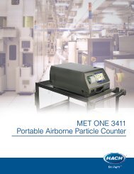
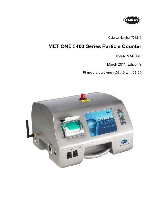
Catalog Number 701241<strong>MET</strong> <strong>ONE</strong> <strong>3400</strong> <strong>Series</strong> <strong>Particle</strong> <strong>Counter</strong>USER MANUALMarch 2011, Edition 9Firmware versions 4.03.10 to 4.05.04
Table of ContentsSection 1 Specifications.................................................................................................................... 7Section 2 General information......................................................................................................... 92.1 Safety information........................................................................................................................ 92.1.1 Use of hazard information................................................................................................... 92.1.2 Precautionary labels ........................................................................................................... 92.1.3 Compliance ....................................................................................................................... 102.2 Country Specific Approval for Wi-Fi Device ............................................................................... 102.3 General product information ...................................................................................................... 112.4 How to use the touchscreen interface........................................................................................ 112.4.1 Touchscreen interaction terminology ................................................................................ 122.5 Accessories................................................................................................................................ 12Section 3 Installation........................................................................................................................ 153.1 Unpack the instrument ............................................................................................................... 153.2 Electrical installation .................................................................................................................. 163.2.1 Wiring safety information ..................................................................................................163.2.2 Electrical connections ....................................................................................................... 173.3 Battery installation...................................................................................................................... 193.3.1 Low battery alert ............................................................................................................... 193.3.2 Using the external battery charger.................................................................................... 203.3.3 Battery status .................................................................................................................... 203.4 Component installation .............................................................................................................. 203.4.1 Install the printer paper ..................................................................................................... 213.4.2 Assemble the isokinetic probe stand ................................................................................ 223.5 Communication installation ........................................................................................................ 243.5.1 Connect RS485 communication ....................................................................................... 243.5.2 Connect RS232 communication ....................................................................................... 253.5.3 Connect for Ethernet communication................................................................................ 253.5.4 Connect for WiFi communication ...................................................................................... 25Section 4 Navigation ........................................................................................................................ 274.1 <strong>Counter</strong> navigation..................................................................................................................... 27Section 5 Configuration .................................................................................................................. 315.1 Configuration overview .............................................................................................................. 315.2 System settings.......................................................................................................................... 315.2.1 Set the time and date........................................................................................................ 315.2.2 Set sleep mode and backlight........................................................................................... 325.2.3 Set Basic or Advanced operation...................................................................................... 325.2.4 Set Alarm Reasons ........................................................................................................... 335.2.5 Manage audible alarms..................................................................................................... 335.2.6 Set the interface language ................................................................................................ 345.2.7 Manage the data buffer.....................................................................................................355.2.8 Manage backup and restore ............................................................................................. 365.2.9 Manage units and alarms.................................................................................................. 375.2.10 Define an alarm............................................................................................................... 385.2.11 Copy the configuration to the USB drive (memory stick) ................................................ 395.2.12 Install a configuration from a USB drive (memory stick) ................................................. 395.2.13 Select the inert gas and altitude...................................................................................... 395.2.14 Beep function .................................................................................................................. 405.3 Area management ..................................................................................................................... 415.3.1 Add a new area................................................................................................................. 425.3.2 Edit an area....................................................................................................................... 425.3.3 Remove an area ............................................................................................................... 423
Table of Contents5.3.4 Change the order of areas on the list ................................................................................425.4 Location management................................................................................................................425.4.1 Add a new location ............................................................................................................435.4.2 Edit a location....................................................................................................................435.4.3 Location settings................................................................................................................445.4.4 Location alarms .................................................................................................................455.4.5 Remove a location.............................................................................................................465.4.6 Change the order of locations ...........................................................................................465.5 Group management ...................................................................................................................475.5.1 Add a new group ...............................................................................................................475.5.2 Load an existing group ......................................................................................................485.5.3 Delete a group...................................................................................................................485.5.4 Add a location to a group...................................................................................................485.5.5 Remove a location from a group .......................................................................................495.5.6 Change the order of locations in a group ..........................................................................495.5.7 Group settings ...................................................................................................................495.5.8 Override group settings .....................................................................................................505.5.9 Group alarms.....................................................................................................................515.6 Sizes Feature .............................................................................................................................515.6.1 Size Configuration .............................................................................................................515.7 Batch ID management................................................................................................................535.7.1 Enter a Batch ID ................................................................................................................535.7.2 Disable the Batch ID..........................................................................................................545.7.3 Set or clear the Batch ID ...................................................................................................545.8 Password protection and user management..............................................................................545.8.1 Enable user logon..............................................................................................................545.8.2 Administrator logon............................................................................................................555.8.3 Change a Password ..........................................................................................................565.8.4 Replace a forgotten password...........................................................................................565.8.5 Manage users....................................................................................................................575.9 Data transfer to the OPC server.................................................................................................60Section 6 Operation ..........................................................................................................................616.1 Log on ........................................................................................................................................616.2 Count test ...................................................................................................................................636.2.1 Change the run location ....................................................................................................646.2.2 View settings during a test.................................................................................................656.2.3 View historical data during a test.......................................................................................656.2.4 Run the filter scan probe ...................................................................................................656.3 Review historical (buffer) data....................................................................................................666.3.1 Historical data filter............................................................................................................666.3.2 Storage of partial data .......................................................................................................676.4 Clear buffer records....................................................................................................................686.5 Print center .................................................................................................................................696.5.1 Manual print setup.............................................................................................................696.5.2 Automatic print setup.........................................................................................................716.5.3 Cancel a print job...............................................................................................................736.6 Test and report wizard................................................................................................................736.6.1 Standard sampling protocols.............................................................................................736.6.2 Generating reports.............................................................................................................746.6.3 Test and report procedure.................................................................................................756.7 Export data .................................................................................................................................796.7.1 Exported data status bit masks .........................................................................................824
Table of ContentsSection 7 Network and communications .................................................................................... 857.1 Serial communication................................................................................................................. 867.2 Ethernet communication ............................................................................................................ 867.3 Wireless communication ............................................................................................................ 877.4 Wireless security........................................................................................................................ 88Section 8 Taking Counts—Quick Reference .............................................................................. 89Section 9 Maintenance .................................................................................................................... 919.1 Cleaning the unit ........................................................................................................................ 919.2 Zero count.................................................................................................................................. 919.3 Update the <strong>3400</strong> software.......................................................................................................... 919.4 Check the battery status ............................................................................................................ 929.4.1 Recharge the battery ........................................................................................................ 939.4.2 Calibrate the battery.......................................................................................................... 949.5 Diagnostics screen overview ..................................................................................................... 949.6 System status printout ............................................................................................................... 959.7 Factory settings screen.............................................................................................................. 959.7.1 <strong>Counter</strong> tab ....................................................................................................................... 969.7.2 Calibration tab................................................................................................................... 979.7.3 Test tab ............................................................................................................................. 97Section 10 Parts and accessories................................................................................................. 9910.1 Parts for 28.3 LPM counter (3413 and 3415)........................................................................... 9910.2 Parts for 50 LPM counter (3423 and 3425).............................................................................. 9910.3 Parts for 100 LPM counter (3445)............................................................................................9910.4 Parts......................................................................................................................................... 9910.5 Spare parts kit (2087919-01) ................................................................................................. 10010.6 Spare part, individual ............................................................................................................. 100Appendix A Service Procedures and Contact Information................................................... 101A.1 Return Procedures .................................................................................................................. 101A.2 Technical Support Information................................................................................................. 101A.3 Customer Support Contact...................................................................................................... 101Appendix B Software Menu Trees............................................................................................... 103B.1 Menu Flow Diagram ................................................................................................................ 103Appendix C Group Settings ......................................................................................................... 107C.1 Group Setting Forms ............................................................................................................... 107Appendix D Sample Status Bit Mask Definitions .................................................................... 111D.1 Overview ................................................................................................................................. 111Appendix E Modbus register maps ............................................................................................ 113E.1 Identification block (registers 0–99)......................................................................................... 113E.2 Configuration block (registers 100–199).................................................................................. 113E.3 Count bin labels (registers 200–299)....................................................................................... 114E.4 Sample data (registers 300–399) ............................................................................................ 114E.5 Sample record control (registers 400–499) ............................................................................. 115E.6 Buffered record (registers 500–599)........................................................................................ 116E.7 Sample mode parameters (registers 600–699)....................................................................... 116E.8 Diagnostic data records (registers 700–749)........................................................................... 117E.9 Sensor calibration information (registers 900–1099)............................................................... 117E.10 Miscellaneous functions (registers 1100–1199) .................................................................... 117E.11 Application-specific (registers 1200–1299)............................................................................ 117E.12 Last sample record (registers 1500–1599)............................................................................ 118E.13 Sample Record Extended 1 (Registers 1600–1699)............................................................. 1195
Table of ContentsE.14 Buffered Record Extended 1 (Registers 1700–1799) ...........................................................119E.15 Last Record Extended 1 (Registers 1800–1899)...................................................................119E.16 Sample Record Extended 2 (Registers 1900–1999) .............................................................119E.17 Buffered Record Extended 2 (Registers 2000–2099) ............................................................119E.18 Last Record Extended 2 (Registers 2100–2199)...................................................................1206
Section 1SpecificationsSpecifications are subject to change without notice.InstrumentLight SourceLong Life Laser diode with 10-year Mean Time To Failure (MTTF), Class 3B laser, 810 to852 nm, 50 mW maximumPump TypeAir vacuum, rated for continuous useCount DisplayColor ¼ VGA TFT touch screenInterfaceWindows CE ® -basedMaximum Count Shown 9,999,999 shownSample Time 6 seconds to 23 hours 59 minutes 59 seconds (23:59:59)Delay/Hold Times 0 second to 23 hours 59 minutes 59 seconds (23:59:59)Count Alarms1 to 9,999,999 countsData Storage50 to 5,000 samples, scrollable on Historical Data review screenCount CyclesUp to 100 while in automatic modeLocationsup to 999 locationsEthernet–10BaseT/100-BaseTRS485 SerialOutputsRS232 SerialWireless 1 –802.11b/g compatibleUSB Client (Version 1.1)USB Host (Version 1.1)ManifoldSupports A3432, 32-port manifold system (available on 1 CFM units only)Enclosure MaterialStainless steel3413 and 3415—7.55 kg (16.6 lb)Weight (without battery) 3423 and 3425—8.33 kg (18.3 lb)3445—8.65 kg (19.0 lb)Size (W x D x H)31.8 x 25.4 x 20.3 cm (12.5 x 10 x 8 in.)EnvironmentOperating0° to 40°C (32° to 104°F); 10 to 90% relative humidity, non-condensingStorage– 40° to 50°C (– 40° to 122°F); 0 to 98% relative humidity, non-condensingWarranty and CertificationsWarrantyInstrument: 2 yearsLong Life Laser Diode: 3 years1 feature - not available with standard models.7
SpecificationsSamplingNumber of Size Ranges Standard 6, 83413 and 3423—0.3, 0.5, 1.0, 3.0, 5.0, 10.0 µm<strong>Particle</strong> Size Ranges andStandard Channels 1 3415 and 3425—0.5, 1.0, 2.0, 3.0, 5.0 and 10.0 or 25.0 µm3445—0.5, 1.0, 2.0, 3.0, 5.0, 10.0 µm3413 and 3415—28.3 L/min (1.00 cfm) ± 5% (Default factory setting)Flow Rate3423 and 3425—50 L/min (1.77 cfm) ± 5% (Default factory setting)3445—100 L/min (3.53 cfm) ± 5% (Default factory setting)Zero CountConforms to JIS B9921. 1 count or less in 5 minutes, 95% confidence level3413 and 3415—5% at 14,126,000 particles/m 3 (400,000 particles/ft 3 )Coincidence Loss3423 and 3425—5% at 4,000,000 particles/m 3 (113,000 particles/ft 3 )3445—5% at 9,500,000 particles/m 3 (84,950 particles/ft 3 )3413 and 3423—50% ± 20 % for 0.3 µm, (100% ± 10% at 1.5 times the minimum sensitivity).Fully complies with ISO21501-4.Counting Efficiency3415, 3425 and 3445—50% ± 20% for 0.5 µm, (100% ± 10% at 1.5 times the minimumsensitivity). Fully complies with ISO21501-4.BatteriesBattery TypeQuantity Included 1Operating Time (Battery)Lithium ion smart battery; can be charged, ejected and changed without disruption tothe system.WARNING: Explosion and fire hazard. Battery substitution is notallowed.3413 and 3415—6 hours 23423 and 3425—7 hours 33445—3.5 hours 4Battery Recharge Time 6.75 hours minimum, 10 hours maximum 5PowerBattery Weight24 VDC 3.2A with 100~240 VAC 50/60 Hz, adapter included in ship kit0.66 kg (1.45 lb)1 Customized channel sizes can be selected at time of order in a range from 0.3 µm to 25.0 µm; however, 0.3 µm and 25.0 µmcannot be configured together.2 Typical battery life is estimated with the following conditions: Two fully-charged batteries placed in a 1CFM unit sampling for 1minute, print record, a 1-minute hold time (simulating continuous sampling mode), then repeating this cycle. The backlightremains on at all times.3 Typical battery life is estimated with the following conditions: Two fully-charged batteries placed in a 50 L/min unit sampling for20 minutes (1 m 3 sample), print record, a 5-minute hold time (simulating move to new location), then repeating this cycle. Thebacklight time-out set to two minutes.4 Typical battery life is estimated with the following conditions: Two fully-charged batteries placed in a 100 L/min unit samplingfor 10 minutes (1 m 3 sample), print record, a 5-minute hold time (simulating move to new location), then repeating this cycle.The backlight time-out set to two minutes. Two batteries are provided with the 3445.5 Typical battery recharge time is estimated with the following conditions: The instrument is turned off or not sampling. Thebattery recharge time increases if the instrument is sampling continuously.8
Section 2General information2.1 Safety information2.1.1 Use of hazard information2.1.2 Precautionary labelsThe information in this manual has been carefully checked and is believed to beaccurate. However, the manufacturer assumes no responsibility for any inaccuracies thatmay be contained in this manual. In no event will the manufacturer be liable for direct,indirect, special, incidental, or consequential damages resulting from any defect oromission in this manual, even if advised of the possibility of such damages. In the interestof continued product development, the manufacturer reserves the right to makeimprovements in this manual and the products it describes at any time, without noticeor obligation.Published in the United States of America.No part of the contents of this manual may be reproduced or transmitted in any form or byany means without the written permission of the manufacturer.Please read this entire manual before unpacking, setting up or operating this equipment.Pay attention to all danger, warning and caution statements. Failure to do so could resultin serious injury to the operator or damage to the equipment.To make sure that the protection provided by this equipment is not impaired, do not useor install this equipment in any manner other than that specified in this manual.DANGERIndicates a potentially or imminently hazardous situation which, if not avoided, willresult in death or serious injury.WARNINGIndicates a potentially or imminently hazardous situation which, if not avoided,could result in death or serious injury.CAUTIONIndicates a potentially hazardous situation that may result in minor or moderateinjury.NOTICEIndicates a situation that is not related to personal injury.Important Note: Indicates a situation which, if not avoided, may cause damage to theinstrument. Information that requires special emphasis.Note: Information that supplements points in the main text.Read all labels and tags attached to the instrument. Personal injury or damage to theinstrument could occur if not observed.Electrical equipment marked with this symbol may not be disposed of in European public disposal systems after12 August of 2005. In conformity with European local and national regulations (EU Directive 2002/96/EC),European electrical equipment users must now return old or end-of life equipment to the Producer for disposal at nocharge to the user.Note: For return for recycling, please contact the equipment producer or supplier for instructions on how to returnend-of-life equipment, producer-supplied electrical accessories, and all auxiliary items for proper disposal.This is the safety alert symbol. Obey all safety messages that follow this symbol to avoid potential injury. If on theinstrument, refer to the instruction manual for operation or safety information.9
General informationThis symbol indicates that a risk of electrical shock and/or electrocution exists.This symbol indicates a laser device is used in the equipment.This symbol indicated the presence of devices sensitive to Electro-static Discharge (ESD) and indicated that caremust be taken to prevent damage with the equipment.This symbol identifies the location of a fuse or current limiting device.2.1.3 ComplianceCLASS 1 LASER PRODUCTThis symbol indicates that the instrument is a Class 1 LASER product.Complies with IEC/EN 60825-1:2007 and 21 CFR 1040.10 except for deviations pursuantto Laser Notice No. 50, dated June 24, 2007. FDA accession number: 9020917.This product is CE compliant. Contact the manufacturer for complete compliance details.2.2 Country Specific Approval for Wi-Fi DeviceProducts with the wireless option contain a Wi-Fi device operating in the 2.4 GHz range.The Antenna used for this transmitter must be installed to provide a separation distanceof at least 20 cm from all persons and must not be co-located or operated in conjunctionwith any other antenna or transmitters.Products with the wireless option contain a Modular RF Device withinUnites States FCC ID: R68WIPORTCanada IC ID: 3867A-WIPORTHarmonized countries approved for operation - ISO Country codesCountry ISO31662 letter code Country ISO31662 letter codeAustria AT Poland PLBelgium BA Portugal PTDenmark DK Spain ESFinland FI Sweden SEFrance FR United Kingdom GBGermany DE Iceland ISGreece GR Norway NOHungary HU Switzerland CHIreland IE Turkey TRItaly IT Netherlands NLMexico MX — —10
General informationRegulatory RF Device Approvals:FCC: Approved as a Modular Device under a TCB Grant of Authorization.FCC ID: R68WIPORTIC: Approved as a Modular Device under Certificat D'Acceptabilite' TechniqueC-REL ID : 3867A-WIPORTCOFETEL: Approved as a modular device by certificate of HomologationCFT: RCPLAW108-1337Notified Body Opinion: Compliant under the R&TTE Directive 1999/5/EC to the essentialsrequirements of Article 3.2 according to the assessment procedures in Article 10(5) andAnnex IV for (class-2 equipment) and marked as CE11772.3 General product informationModel NumberThis manual describes use of the <strong>MET</strong> <strong>ONE</strong> <strong>3400</strong> <strong>Series</strong> <strong>Particle</strong> <strong>Counter</strong>s (Table 1).Refer to Section 1 on page 7 for complete specifications.The particle counters use a laser-diode light source and collection optics for particledetection. <strong>Particle</strong>s scatter light from the laser diode. The collection optics focus the lightonto a photo diode that converts the bursts of light into electrical pulses. The pulse heightis proportional to the particle size. Pulses are counted and their amplitude is measuredfor particle sizing. Results are shown as particle counts in the specified size range(differential count mode) or as total particle counts (cumulative count mode). Amicroprocessor controls all instrument functions. Count data is shown as cumulativecounts or differential counts.The particle counter is thoroughly inspected and tested at the factory and is ready for useupon receipt. When received, inspect the shipping carton for damage. If the carton isdamaged, notify the carrier and save the carton for carrier inspection. Inspect the counterfor broken parts, scratches, dents or other damage.Table 1 <strong>MET</strong> <strong>ONE</strong> <strong>3400</strong> <strong>Series</strong> particle counter model numbersL/minFlow Ratecubic ft/minMinimum <strong>Particle</strong> Size Channel (μm)3413 28.3 1 0.33415 28.3 1 0.53423 50 1.77 0.33425 50 1.77 0.53445 100 3.53 0.52.4 How to use the touchscreen interfaceThe <strong>MET</strong> <strong>ONE</strong> <strong>3400</strong> is operated by use of a TFT color touchscreen located on the frontpanel of the unit (Figure 3 on page 18). All commands are executed through thetouchscreen.Make contact with the screen through the use of a single finger or the provided stylus.Notice: To avoid damage to the touchscreen interface, only make contact with a finger orthe provided stylus. Avoid the use of sharp objects or the “writing” end of pens and pencils.Use only light touch—never use force with the touchscreen interface.11
General information2.4.1 Touchscreen interaction terminologyThroughout this document, user interaction with the touchscreen will be described withspecific terminology (Table 2).Table 2 Touchscreen interaction terminologyTermPushSelectHighlightInteraction with the Graphical User Interface on the Instrument Touch ScreenActivate a button or iconActivate a field or a tab optionActivate a list option2.5 AccessoriesScreen items commonly referred to in this manual include:• A screen is a window of the Graphical User Interface (GUI) which takes up all visiblespace on the touchscreen and can only be exited by pressing a button.• A tab is a subdivision of the GUI easily accessed by touching the tab at the top of thescreen.• An icon is an area of the touchscreen that should be touched to access anotherscreen or execute an action (such as performing a sample run).• A button is an area of the touchscreen that should be touched to access anotherscreen or execute an action (such as clearing the buffer).• A field indicates an area of the screen where strings of text and/or numbers may beentered. To enter information in a field, touch the field with a finger or a stylus.Depending on the nature of the field, a keypad will appear on the touchscreen to allowtext or numeric entries. To complete entries from a keypad entry, push OK.• A check box allows functions to be toggled on or off. Push the box with a finger orstylus to show a checkmark and enable the function.• A dropdown menu allows operators to choose from a set list of values. Dropdownmenus can be identified by the arrow on the right side of the field. To use a dropdownmenu, push the arrow with a finger or a stylus to show the list. Drag a finger or a stylusdown the list to show all items, then highlight the item to select it.• A pop-up box is a warning or note to make sure actions are taken as intended. PushOK to continue or CANCEL to stop.Several accessories are available to customize counter functions (Table 3). Theseaccessories can be ordered from a local manufacturer representative or from the factory.For contact details, refer to Appendix A on page 101.Refer to Section 10 on page 99 for all parts and accessories.Table 3 <strong>MET</strong> <strong>ONE</strong> <strong>3400</strong> series particle counter accessoriesAccessoryPortAll Version 2 Software,Demo VersionStylusIncluded/IncludedIncludedDescriptionPortAll Software controls the counter from a PC; downloads count datainto the PC; sorts, normalizes, calculates for cleanroom classification. Callyour manufacturer representative or customer support to purchase apermanent license.In cleanroom environments where operators wear protective gloves thatmay inhibit movement, a stylus permits easier manipulation of thetouchscreen.12
Table 3 <strong>MET</strong> <strong>ONE</strong> <strong>3400</strong> series particle counter accessories (continued)General informationAccessoryIncluded/DescriptionPower supply and cords Included120/240 VAC AC-to-DC power supplyPower cord (US)Power cord (EU)The power supply can be used in addition to battery power.Thermal paper for printer Included Two rolls are included with the <strong>MET</strong> <strong>ONE</strong> <strong>3400</strong>.Extension tube for isokineticprobeIncluded This tubing allows connections from the probes to the counter.Isokinetic probeIncludedThe isokinetic probe is for use with unidirectional air flows to maximizecorrelation between counts and actual particle-size distribution. Theisokinetic probe comes with a tripod stand, probe clamp and extensiontube. The isokinetic probe can also be used for handheld spot checks.RH/Temperature probeThe probe plugs into the left side of the counter and monitors relativehumidity and temperature. The results are shown and can be printed.Air velocity probeThe air velocity probe plugs into the left side of the counter. The probemonitors air velocity up to 200 feet/minute (1016 millimeters/second). Theresults are shown and can be printed.Zero count filterIncludedThe zero count filter attaches to sensor inlet and keeps external particlesfrom contaminating the sensor while purging the sensor of internalparticles.Carrying caseA carrying case protects the counter during shipment and storage.Spare batteriesSpare batteries allow maximum flexibility with portable use.(One battery is included with the <strong>MET</strong> <strong>ONE</strong> 3413, 3415, 3423 and 3425.Two batteries are included with the <strong>MET</strong> <strong>ONE</strong> 3445.)External battery chargerAn external battery charger ensures any spare batteries are prepared foruse at any time.High pressure diffuserA high pressure diffuser that can be used in applications to monitormonitor certain pressurized inert gases for air particles.Filter scan probeA handheld probe that can be used to investigate potential sources ofparticles such as air filters. This probe sounds a beep and has a light thatilluminates when a particle is detected.Allows fixed particle size channels to be set in the standard 6 channelinstrument. Options include:Custom channel sizes• 0.5 and 5.0 µm only• 6 custom channel sizes from 0.5 to 25.0 µm• 6 custom sizes from 0.3 to 10 µm 1User-selectable 8 channelsizesAllows the user to configure 2 to 8 particle channel sizes.RS485 connector assembly Included Male RS485 connector assembly to terminate customer cablingUSB Flash driveIncludedUSB Flash drive to transfer data, copy configuration and install softwareupgrades.Intake cleaning brush Included Brush to clean the sample intake nozzle of the particle counterWireless antenna Included Included with the <strong>MET</strong> <strong>ONE</strong> <strong>3400</strong> wireless models only1 Not available for the <strong>MET</strong> <strong>ONE</strong> 3445.13
General information14
Section 3Installation3.1 Unpack the instrumentDANGERPotential personal injury hazard. Only qualified personnel should conduct thetasks described in this section of the manual.Remove all items from the shipping container and inspect them for damage. Make surethat all of the items listed are included (Figure 1). If any of the items are missing ordamaged, contact the manufacturer.A software CD, user manual and WEEE datasheet are also shipped with the <strong>3400</strong><strong>Particle</strong> <strong>Counter</strong>.Figure 1 Instrument components1 <strong>3400</strong> <strong>Series</strong> <strong>Particle</strong> <strong>Counter</strong> 9 Isokinetic probe2 Rechargeable battery 1 10 Extension tube for isokinetic probe3 AC-to-DC power supply 11 Zero count filter4 Power cord (US) 12 RS485 connector assembly5 Power cord (EU) 13 USB Flash drive6 Thermal paper for printer (2 rolls) 14 Intake cleaning brush7 Clamp, isokinetic probe holder 15 Wireless antenna for WiFi8 Tripod, isokinetic probe holder 16 Stylus for touchscreen interface1 Two rechargeable batteries are provided with the <strong>MET</strong> <strong>ONE</strong> 3445.15
Installation3.2 Electrical installation3.2.1 Wiring safety informationFollow all warnings and notes when making wiring connections to the instrument (Safetyinformation on page 9).NOTICEAlways disconnect power to the instrument when making electrical connections.3.2.1.1 Electrostatic discharge (ESD) considerationsImportant Note: To minimize hazards and ESD risks, maintenance procedures notrequiring power to the counter should be performed with power removed.Delicate internal electronic components can be damaged by static electricity, resulting indegraded instrument performance or eventual failure.The manufacturer recommends taking the following steps to prevent ESD damage toyour instrument:• Before touching any instrument electronic components (such as printed circuit cardsand the components on them) discharge static electricity from the body. To dischargestatic electricity, touch an earth-grounded metal surface such as the chassis of aninstrument, or a metal conduit or pipe.• To reduce static build-up, avoid excessive movement. Transport static-sensitivecomponents in anti-static containers or packaging.• To discharge static electricity from the body and keep it discharged, wear a wriststrap connected by a wire to earth ground.• Handle all static-sensitive components in a static-safe area. If possible, useanti-static floor pads and work bench pads.16
3.2.2 Electrical connectionsInstallationConnect probes, external power, cables or USB devices to the Model <strong>3400</strong> to expandcounter functionality or download data. Make connections where indicated (Figure 2 andFigure 3 on page 18).Figure 2 Back view1 Exhaust port 1 4 Manifold controller connector—standard RS232 port(available on 1 CFM units only)2 Serial communications RS485 connector 5 Battery ports3 Auxiliary I/O port for filter scan probe 6 Supplemental feet1 The exhaust port has a 3 /8” NPT thread to support a 3 /8” NPT to 3 /8” hose barb adapter (P/N 580854).Note: Do not install an exhaust fitting in the exhaust port of a <strong>MET</strong> <strong>ONE</strong> 3445.17
InstallationFigure 3 Front and side view1 Sample intake nozzle 1 8 USB host connector2 Touchscreen 9 USB client connector3 Power button 10 Relative humidity/temperature probe connector4 Battery status indicator 11 Air velocity probe connector5 Ethernet connector 12 Handle6 Handle 13 Wireless antenna connector7 Printer 14 Power connector1 Shown with the protective cap installed. Remove the protective cap before operation.Note: Hach Company recommends using Hach Company-furnished USB flash drives with the <strong>3400</strong>;contact Customer Service for additional support at 800.866.7889 or +1.541.472.6500.18
Installation3.3 Battery installationWARNINGExplosion and fire hazard. Battery substitution is not permitted. Use only Hachbattery 280-120-2024 in MetOne <strong>Particle</strong> <strong>3400</strong> counters.1. To open the battery compartment, turn the latches ¼ turn to the left and then pulldoor open.2. Insert the batteries (Figure 2 on page 17). Do not force the batteries into place. Installat least one battery in the <strong>MET</strong> <strong>ONE</strong> 3413, 3415, 3423 and 3425. Install two batteriesin the <strong>MET</strong> <strong>ONE</strong> 3445.Note: When operating from battery power, the <strong>MET</strong> <strong>ONE</strong> 3445 will turn on with only one battery, butwill not sample until two batteries are installed.3. Attach the power supply to the unit (Figure 3 on page 18).4. Connect the unit power supply to external power through the AC power adapter. Theunit will automatically turn on when charged batteries are installed or AC poweris connected.5. Once the unit is on, charge the batteries until they are fully charged. The batterystatus light indicates the level of power in the battery (Table 4).Note: The batteries cannot overcharge.Batteries installed in the particle counter will charge when the AC power cord isconnected. An external battery charger is also available for maximum efficiency (Section10 on page 99). Contact a local Hach Company agent at 800.866.7889 or+1.541.472.6500 to order.• Batteries charged in the <strong>3400</strong> will take approximately 10 hours to charge completely.• Batteries charged in an external charger will take approximately 7 hours tocharge completely.• Depending on the hysteresis characteristics and calibration status of the batterysystem, batteries may not be 100% chargeable during each charge cycle. Batteriesare considered fully charged if the display reads between 95% and 100%.Note: It is recommended that a battery is recalibrated using the smart battery charger(280-300-5000) if a fully charged battery shows less than 95% charge.The battery status for batteries installed in the counter is indicated by the state of the LEDon the front of the unit (Table 4).Table 4 Battery LED color indicationsLED state LED color Battery status Charging or not charging?Flashing Orange Low power Not chargingFlashing Green Low power ChargingSolid Green Charged Charging3.3.1 Low battery alertWhen the total available battery charge drops below 15% of total capacity, a warning willshow and the system will begin beeping once every 5 seconds.When the total available battery charge drops below 5%, the system will beep once asecond for 15 seconds before shutting down.19
Installation3.3.2 Using the external battery charger3.3.3 Battery statusIcon State DescriptionWARNINGExplosion and fire hazard. Charger substitution is not permitted. Use only thecharger specified in Spare parts kit (2087919-01) on page 100.The external battery charger is an accessory with a separate set of instructions. Chargethe batteries in the external battery charger per the manufacturer’s instructions.The battery status is indicated with a battery icon in the user interface (Table 5). A statusis given for each individual battery.• A maximum of two batteries may be loaded into the <strong>3400</strong> at one time.• If only one battery is loaded into the <strong>3400</strong>, only one icon will appear on the taskbar.Table 5 Battery StatusOKBattery installed and is completely chargedChargingAC power is present and the battery is being chargedErrorNot installedor fullchargeWhen the “!” symbol is pressed, a new screen appears and the instrument determines if thebattery requires calibration or if there is a communication problem. If the battery requirescalibration, insert the battery into the Smart Charger (P/N 280-300-5000) and follow theinstruction provided with the charger. Contact Customer Service for Smart Chargerpurchasing information.Batteries are not installed or the batteries are fully charged. The <strong>3400</strong> is running on ACpower.3.4 Component installationWARNINGExplosion and fire hazard. Charger substitution is not permitted. Use only theSmart Charger specified by the manufacturer. Refer to section 10.4 on page 99.DANGERExplosion hazard. Do not attempt to sample reactive gases (such as hydrogen oroxygen) with the particle counter. Reactive gases create an explosion hazard in thecounter. Contact a local Hach Company representative or the factory at800.866.7889 or +1 541.472.6500 for more information abouthazardous applications.Important Note: Keep the exhaust port clear of obstacles or obstructions.1. Locate the counter in a clean environment. The <strong>3400</strong> can be seated either on itsbottom feet or its back feet as needed.2. Remove the protective cap from the inlet tube on top of the counter.Important Note: To avoid damage to the counter, never operate the counter with theprotective cap in place.20
3.4.1 Install the printer paperInstallation3. After shipping or storage, the counter batteries may need to be charged. Until thebatteries are completely charged, run the <strong>3400</strong> on AC power.a. Connect the AC-to-DC power supply to the DC connector on the left side of theunit.b. Connect the AC-DC power supply to AC power (Figure 3 on page 18). Thecounter will turn on.Note: Only use the HUA-furnished power supply with the <strong>3400</strong>. Substitution of another power supplymay damage the unit and will void the product warranty.The <strong>MET</strong> <strong>ONE</strong> <strong>3400</strong> features an integrated printer located on the front of the unit. Referto print center for complete procedures (section 6.5 on page 69).Important Note: To prevent damage to the print head, the printer should not be operatedwithout paper. If the particle counter must be operated without paper in the printer, set thePrint Mode to None.Important Note: Paper used in this printer is temperature-sensitive on one side and mustgo into the printer as explained in the instructions. Do not substitute other types of paper.To install a roll of printer paper:1. Locate the printer on the front of the unit (Figure 4 on page 22).2. Pull up the green handle in the center of the paper cover until a click is heard.3. Fold the door down and remove the tube from the previous roll.4. Install the new paper roll so the paper feeds from the top of the roll. Position the endof the paper over the black roller at the end of the printer feed door. Do not thread thepaper under the roller.5. Push the printer door back until it clicks into place.6. The printer is now ready.Note: If the paper does not feed out or no image appears on the paper after a print command hasbeen sent, check the orientation of the paper roll.21
InstallationFigure 4 Printer paper installation3.4.2 Assemble the isokinetic probe standThe isokinetic probe can be stationed at a distance from the particle counter with theprobe stand and the extension tubing (Figure 5 on page 23).1. Attach the probe clamp to the tripod. Turn the clamp until it is secure.2. Insert the probe into the probe clamp. Tighten the knob on the clamp.3. Attach the extension hose to the isokinetic probe.22
InstallationFigure 5 Isokinetic probe stand1 Probe 2 Probe clamp 3 Tripod stand23
Installation3.5 Communication installation3.5.1 Connect RS485 communicationConnect the RS485 connector to the unit. Refer to serial communication for setupprocedures (section 7.1 on page 86).Tools needed:• Small flat-blade screwdriver• Wire stripper1. Strip ¼-inch (6.0 mm) of the insulation from the end of each wire.2. Insert each stripped wire into the connector (Figure 6). All three wires should beconnected for proper RS485 connection. The wire insulation should be seatedagainst the connector. Do not leave bare wire exposed.3. Tighten each screw to secure the wire.4. Install the wire tie through one "Shell" half and around the cable (Figure 6, Item 7).Snap the two "Clam Shells" together and over the connector.5. Plug the connector into the unit.Figure 6 Install the RS485 connector1 Position 1 (RS485A signal, white wire) 5 Wire tie strain relief2 Position 2 (RS485B signal, blue wire) 6 Cable 13 Position 3 (RS485 common, clear or natural color) 7 Connector clam shell4 Connector screw (2x)1 Recommended cable type: Belden 9841 or equivalent24
3.5.2 Connect RS232 communicationConnect the RS232 connector to the unit. Refer to serial communication for setupprocedures (section 7.1 on page 86).InstallationTools needed:• Small flat-blade screwdriver1. Plug the RS232 cable into the unit (Figure 2 on page 17, item 4).2. Secure the RS232 connector to the unit by tightening the connector screws with thescrewdriver.3.5.3 Connect for Ethernet communicationPlug the Ethernet cable into the unit (Figure 3 on page 18, item 5). Refer to the Ethernetcommunication section for setup procedures (section 7.2 on page 86).3.5.4 Connect for WiFi communicationAttach the provided antenna at the wireless connection (Figure 3 on page 18, item 13).Refer to the wireless communication and wireless security sections for setup procedures(section 7.3 on page 87 and section 7.4 on page 88).25
Installation26
Section 4Navigation4.1 <strong>Counter</strong> navigationThe <strong>MET</strong> <strong>ONE</strong> <strong>3400</strong> Airborne <strong>Particle</strong> <strong>Counter</strong> system and measurement configuration isaccessed through the <strong>Counter</strong> Navigation screen (Figure 7). Push an icon to access theconfigurable settings for that function (Table 6).Refer to the software menu trees section for the complete menu structure (Appendix B onpage 103).Figure 7 <strong>Counter</strong> Navigation screenTable 6 <strong>Counter</strong> navigation screen icon descriptionsIcon Functions Relevant section(s)SampleHistoricalExport• Run/Stop• System Diagnostics• Battery Diagnostics• Login• Return to <strong>Counter</strong> Navigation• Filter probe test• RETURN arrow to <strong>Counter</strong> Navigation• Historical measurement screen• Scroll buffered data• Print Data• Export Data• Filter Data• Output file as Comma Separated Value• Output file as Tab Separated File• Output file as PortAll• Name fileCount test on page 63Review historical (buffer) data onpage 66Historical data filter on page 66Report test data on page 78Exported data status bit masks onpage 8227
NavigationPrinterLocationsGroupSystem• Sample print mode• Cycle print order• Print average/round average• Print buffer• Add/edit/remove areas• Add/edit locations—copy settings from a location,configure or change settings, configure or changealarms• Remove locations• Print areas and locations• Load group• Add group• Edit group• Time• Date• Sleep time• Backlight timeout• Require logon• Set sounds• Add/edit users• GasTable 6 <strong>Counter</strong> navigation screen icon descriptions (continued)Icon Functions Relevant section(s)• Altitude (ft)• Delete group• Print group• Choose between usinggroup settings or locationsettings• Buffer size• Clear buffer• Select language• Restart• Factory backup/restore• Filter scan probe• Set units/flow rate alarm• Copy/read aconfigurationTest and report wizard on page 73Export data on page 79Report test data on page 78Location management on page 42Group management on page 47System settings on page 31Set the interface language on page 34Set the time and date on page 31Set sleep mode and backlight onpage 32Manage audible alarms on page 33Manage the data buffer on page 35Set the interface language on page 34Manage backup and restore onpage 36Manage units and alarms on page 37Manage units and alarms on page 37Define an alarm on page 38DiagnosticsSizes• Signal, value and status report• Print report• Add size• Edit size• Delete sizeNote: <strong>Particle</strong> size configurationis available when the 8 channeloption is purchased.Diagnostics screen overview onpage 94FactoryLogonOnly printing information. These screens contain information useful for system diagnostics, includingcalibration expiration information. These screens are for factory use only. Refer to Factory settings screenon page 95.• User Logon screenInput User NameInput PasswordChange Password28
NavigationTable 6 <strong>Counter</strong> navigation screen icon descriptions (continued)Icon Functions Relevant section(s)• Test and report wizard for ISO, EU-GMP, FS or BSclassification complianceTest Wizard• Return to the previous screen or menuReturn29
Navigation30
Section 5Configuration5.1 Configuration overview5.2 System settingsSystemThis section describes tasks that are not done frequently. Many of these tasks are doneonly at the initial commissioning stage. Other tasks are done as updates to the <strong>MET</strong> <strong>ONE</strong><strong>3400</strong> are needed.Important Note: When user passwords are used, it is necessary for the user to be loggedin at the ADMINISTRATOR level to do most of the following tasks.Tasks in this section are grouped into:• System settings (section 5.2 on page 31)• Area management (section 5.3)• Location management (section 5.4 on page 42)• Group management (section 5.5 on page 47)• Sizes feature (section 5.6 on page 51)• Batch ID management (section 5.7 on page 53)• Password protection and user management (section 5.8 on page 54)Global system settings control basic functions, such as setting the time and date, users,options and accessories and replication of setup. To access global settings for the system,push SYSTEM on the <strong>Counter</strong> Navigation screen.Global system settings are organized into seven tabs (Figure 8). The interface includes ascroll bar to access tabs that are not visible.Figure 8 Global system settings screen5.2.1 Set the time and date1. On the <strong>Counter</strong> Navigation screen, push SYSTEM. Select the Basic tab (Figure 8).2. Select the Time field. Use the numeric keypad to enter the current time in HH:MM:SSformat. Push ENTER to confirm and return to the Basic tab.3. Select the Date field. Use the numeric keypad to enter the current date inYYYY-MM-DD format. Push ENTER to confirm and return to the Basic tab.31
Configuration5.2.2 Set sleep mode and backlightNote: These functions operate only during BATTERY operation. They are deactivated when theinstrument is connected to the AC mains.In sleep mode, the unit is put in total hibernation to conserve power. All subsystems arepowered down. The backlight setting only turns off the LCD backlight.The time value for sleep mode is expressed in minutes. The backlight timeout value isexpressed in seconds.1. On the <strong>Counter</strong> Navigation screen, push SYSTEM. Select the Basic tab (Figure 8 onpage 31).2. Select the Sleep Time (minutes) field. Use the numeric keypad to enter the length ofidle time before the counter goes into sleep mode (1 to 30 minutes).Enter 0 minutes to disable the sleep mode.3. Push ENTER to confirm and return to the Basic tab.4. Select the Backlight Timeout (seconds) field. Use the numeric keypad to enter lengthof idle time before the user interface backlight turns off (5 to 300 seconds).Enter a value less than 5 to disable the backlight timeout.5. Push RETURN to confirm and return to the Basic tab.6. To bring the unit out of sleep mode or backlight timeout, use a finger or stylus to turnon the display and power the subsystems.5.2.3 Set Basic or Advanced operationAt startup, the user can set the operation mode to Basic or Advanced mode.Use the Basic mode to:• Do all particle measurement functions• Save run data in the bufferUse the Advanced mode to:• Export dialogs• Measure air velocity• Set analog alarms• Set standards wizards/reports• Backup, restore or restart• Copy a configuration• Set the network protocol (serial, ethernet, WiFi)• Manage areas and locations• Manage user accounts and security• Set user-configurable particle sizes• Filter dataTo set or change the operation mode:1. Power on the instrument.2. The operation mode selection screen will show for 10 seconds. The user can:32
5.2.4 Set Alarm Reasons• Make a selection of advanced or basic• Wait 10 seconds for the instrument to start in the last operation mode.To change from advanced to basic mode:1. Go to the System Settings screen.2. Select the Custom tab.3. Select BASIC MODE.4. Navigate to another screen to restart the instrument automatically.ConfigurationTo capture data about why alarms occur, the Alarm Reason option is set as Required orOptional. In Required or Optional mode, the user is prompted to select from preset alarmreasons for the alarm event.To set Alarm Reasons:1. Go to the System Settings screen.2. Select ALARM REASONS.3. On the Alarm Reasons screen, select REQUIRED, OPTIONAL or DISABLED. Refer toTable 7 for more information.Note: Alarm Reasons are set to Disabled by default.Table 7 Alarm Reasons optionsOptionRequiredOptionalDisabledDescriptionAfter doing a user-initiated sample cycle, the user is required to enter information about all alarmsthat happen during the cycle. 1 Alarm reasons must be defined in the Alarm Reasons screen. Theuser cannot exit the Alarm History screen until a reason has been entered for all alarms.After doing a user-initiated sample cycle, the user is prompted to enter information about allalarms that happen during the cycle. Alarm reasons must be defined in the AlarmReasons screen. To show alarms with no reasons assigned, push the UNASSIGNED ALARMSFILTER button on the Alarm History screen.The user is not prompted to enter information about alarms.1 When a user is logged in as an administrator, the Required mode allows for optional entry of alarm reasons.5.2.5 Manage audible alarmsAll users can enter alarm reasons. Only administrators, factory users or users with theSystem Settings permission set can change the Alarm Reasons mode.The Sounds tab lets the user select the sound and volume that confirm user interfaceactions (Figure 9). The sounds used for audible alarms for stop errors, limit alarms andwarnings are also selected in this tab.33
ConfigurationFigure 9 Sounds tab1. On the <strong>Counter</strong> Navigation screen, push SYSTEM. Select the Sounds tab.2. Select the User Feedback field to show the list of available notification sounds.Selecta sound.3. Move the slider to set the user feedback sound volume.4. Select the Stop Error field to show the list of available alarm sounds. Select a sound.5. Select the Alarm Limit field to show the list of available alarm sounds. Select a sound.6. Select the Warning field to show the list of available alarm sounds. Select a sound.5.2.6 Set the interface languageNote: The instrument must be restarted when the user interface language is set or changed for thechange to take effect.1. On the <strong>Counter</strong> Navigation screen, push SYSTEM. Select the Options andAccessories tab (Figure 10).2. Select the Language field to show the language options.3. Select a language.4. Push OK to restart the instrument.34
ConfigurationFigure 10 Interface language5.2.7 Manage the data bufferThe default setting of the <strong>3400</strong> data buffer is non-rotating or fixed. In this mode, once thedata buffer is completely filled, no new data is loaded in the data buffer. Alternately, theuser can rotate the data buffer.To rotate the buffer, check the Rotate Buffer check box in the Options and Accessoriestab. In this mode, data is continuously loaded even after the buffer is completely filled. Todo this, the oldest data in the buffer is overwritten with the latest data.To clear the data buffer:1. On the <strong>Counter</strong> Navigation screen, push SYSTEM. Select the Options andAccessories tab (Figure 11 on page 36).2. Push CLEAR BUFFER.To set the data buffer size:Important Note: A change to the buffer size causes all current buffer data to be lost andunrecoverable.1. On the <strong>Counter</strong> Navigation screen, push SYSTEM. Select the Options andAccessories tab (Figure 11 on page 36).2. Select the Data Buffer Size field. Use the numeric keypad to enter a value between50 and 5000.3. Push ENTER.4. Select YES to clear the data buffer.35
ConfigurationFigure 11 Manage buffer data5.2.8 Manage backup and restoreTo make a backup of all configurable settings (Figure 12 on page 36):1. On the <strong>Counter</strong> Navigation screen, push SYSTEM. Select the Options andAccessories tab.2. Push BACKUP.An electronic copy of the current configuration is stored in the <strong>3400</strong> memory. This versionof the configuration can be recovered using the Restore function.Use the Restore function when instrument settings become corrupted, accidentallymodified or when the software performs abnormally.To restore configurable settings from the last backup:1. On the <strong>Counter</strong> Navigation screen, push SYSTEM. Select the Options andAccessories tab.2. Push RESTORE.Figure 12 Backup and restore settings36
5.2.9 Manage units and alarmsConfigurationTo set the display units:1. On the <strong>Counter</strong> Navigation screen, push SYSTEM. Select the Units and Alarms tab(Figure 13 on page 37).2. Select the Temperature field. Select Celsius (Deg C) or Fahrenheit (Deg F).3. Select the Air Velocity field. Select mm/Sec or ft/Min.4. Select the Flow Rate field. Select LPM or CPM.To enable the Flow Rate Alarm:1. Select the Enabled check box.2. Select the High field. Use the numeric keypad to enter a value between 5 and 20.3. Select the Low field. Use the numeric keypad to enter a value between 5 and 20.The standard RH/Temperature probe is used in most cases. If a Vaisala HMP probe(2088928) is used, select the HMP RH/T check box.Note: The scaling for the standard probe is different than the scaling for the Vaisala HMP probe. Ifthe readings for your RH/Temperature probe are notably different than expected, make sure thecheck box is appropriately selected or deselected according to the type of probe being used.Figure 13 Configure units and alarms5.2.9.1 Add an alarm reasonAn alarm reason can be added to any data record in the buffer that has an alarm (refer toDefine an alarm on page 38). The alarm reason should describe the reason why the alarmoccurred.Alarm reasons (text strings) must be added to the Alarms Reasons list by the user beforethey can be added to data records.To add an alarm reason to the Alarm Reasons list:1. Push REASONS.2. Push ADD. Use the numeric keypad to enter a reason (up to 29 characters).3. Push ENTER.37
Configuration5.2.9.2 Edit an alarm reason5.2.9.3 Remove an alarm reason5.2.10 Define an alarmHistoricalTo change an alarm reason in the Alarm Reason list:1. Push REASONS.2. Select a reason from the list.3. Push EDIT. Use the numeric keypad to change the text string.To remove an alarm reason from the Alarm Reason list:1. Push REASONS.2. Select a reason from the list.3. Push REMOVE.Alarm reasons (text strings) that have been added to the Alarms Reasons list by the user(section 5.2.9.1 on page 37) can be added to any data record that has an alarm. Alarmreasons that have been added to data records in the buffer are shown on the Historicalscreen and on prints, and are also included in Modbus and all USB Flash drive exports.To add an alarm reason to a data record in the buffer:1. On the <strong>Counter</strong> Navigation screen, push HISTORICAL (Figure 14).2. Select the Data Buffer field. Use the numeric keypad to enter the record number.3. Push ENTER.4. Select the yellow text below Counts.5. Select an alarm reason. Push OK.Figure 14 Define an alarm38
5.2.11 Copy the configuration to the USB drive (memory stick)Configuration1. On the <strong>Counter</strong> Navigation screen, push SYSTEM. Select the Configuration tab.2. Insert a USB drive into the USB host (Figure 3 on page 18, item 8).3. Push COPY CONFIGURATION TO USB (Figure 15). Wait for confirmation message.Push OK to clear message.4. Remove the USB drive.Figure 15 Copy system configuration5.2.12 Install a configuration from a USB drive (memory stick)1. On the <strong>Counter</strong> Navigation screen, push SYSTEM. Select the Configuration tab.2. Insert a USB drive into the USB host (Figure 3 on page 18, item 8).3. Push READ CONFIGURATION FROM USB. Wait for confirmation message.4. Remove the USB drive.5. Push OK to restart the instrument to load a new configuration.5.2.13 Select the inert gas and altitudeThe <strong>3400</strong> must be calibrated at the factory before an inert gas can be selected.Note: The unit applies a correction factor to the flow rate calculation based on the gas selected.1. On the <strong>Counter</strong> Navigation screen, push SYSTEM. Select the Custom tab(Figure 16).2. Select the Gas field. Select the gas to be tested.3. Select the Altitude field. Select the altitude (in feet) of the measurement location.39
ConfigurationFigure 16 Inert gas selection5.2.14 Beep functionNote: The beep function is separate from the standard alarm settings.To set an alert for when a particle count is measured on a specified channel:1. On the <strong>Counter</strong> Navigation screen, push SAMPLE.2. Select the Settings tab on the right side of the screen.3. Select Quick Settings.4. Push YES to edit the settings for the Default Group.5. Select the Run Mode field. Select Beep (Figure 17).Figure 17 Beep setting40
Configuration5.3 Area managementLocationsLocations, Areas and GroupsThe sampling positions (or LOCATIONS) can be organized within larger spaces (orAREAS). This arrangement is a function of the geographical placement of the samplingposition within a facility. Data from each sampling position (or LOCATION) is associatedwith a unique numerical designation assigned automatically by the instrument (range of001 to 999) plus the common name for that point assigned by the user, such as LAFBench 32 or Diffusion Oven Loader. It is permissible to have duplicate LOCATIONnames within separate AREAS. For example, LAF Bench #2 could be a designation forCleanroom 422 and also Cleanroom 423 as long as the combination ofAREA/LOCATION name is unique.In addition, each sample point or LOCATION can be associated with a GROUP that hascommon sampling attributes or sampling recipe as defined by the user. Examples mightbe All ISO Class 7 positions in Building 4 or All Locations Sampled Once a Month. Itis permissible for a LOCATION to belong to one or more GROUPS. It is also possible tohave LOCATIONS that have no GROUP association at all.These combinations of LOCATIONS as AREAS or GROUPS allow for quickerdevelopment of sampling strategies relating to alarm levels, sampling methodology and/orfrequency.Once a library of LOCATIONS, AREAS and GROUPS is developed for a facility, thisinformation can be rapidly transferred to other <strong>3400</strong> series instruments. To transfer theinformation, copy the configuration of the Master <strong>3400</strong> to a USB memory stick and thentransfer that configuration to the remaining <strong>3400</strong> particle counters. Refer to Define analarm on page 38.An area defines a specific place within a facility, such as a clean room, that is identified forsample testing.When area configuration is complete, continue to push RETURN to navigate back to the<strong>Counter</strong> Navigation screen (Figure 18).Figure 18 Area/Location setup41
Configuration5.3.1 Add a new area5.3.2 Edit an area5.3.3 Remove an areaNote: An area name may consist of any combination of up to 15 alphanumeric characters.1. On the <strong>Counter</strong> Navigation screen, push LOCATIONS.2. On the Area/Location Setup screen, push ADD AREA.3. Use the alphanumeric keypad to enter the area name. Push ENTER.Note: Use the ALT key to access special characters.An area can be renamed, using up to 15 characters.1. On the <strong>Counter</strong> Navigation screen, push LOCATIONS.2. On the Area/Location Setup screen, select an area from the list. Push EDIT AREA.3. Use the alphanumeric keypad to rename the area. Push ENTER.Note: Use the ALT key to access special characters.1. On the <strong>Counter</strong> Navigation screen, push LOCATIONS.2. On the Area/Location Setup screen, select an area from the list. Push REMOVEAREA.3. In the confirmation dialog box, push YES to delete the area and all its locations orpush NO to cancel.5.3.4 Change the order of areas on the list5.4 Location managementNote: Changing the listed order of areas will change the order of appearance of locations on thescreen for selection purpose only.1. On the <strong>Counter</strong> Navigation screen, push LOCATIONS.2. On the Area/Location Setup screen, select an area from the list. Push the UPARROW or DOWN ARROW to change the position of the area in the list.3. Continue to select and move areas to create the needed sampling order.A location defines a space within an area, such as a work bench, that is identified forsample testing. A location must be configured within the context of an area.When location configuration is complete, continue to push RETURN to navigate back tothe <strong>Counter</strong> Navigation screen.Locations• Refer to the location settings to copy or configure location-specific settings(section 5.4.3 on page 44).• Refer to location alarms to configure location-specific alarms (section 5.4.4 onpage 45).Return42
5.4.1 Add a new location1. On the <strong>Counter</strong> Navigation screen, push LOCATIONS.Configuration2. On the Area/Location Setup screen, select an existing area, or if needed, create anew area and then select it. Push ADD LOCATION.3. In the Add Sample Location screen:• Select the Location Name field. Use the alphanumeric keypad to enter thelocation name. Push ENTER to confirm.Note: Use the ALT key to access special characters.• Select the Location ID field to specify a numerical ID for the location (Figure 19).The numerical ID is unique for each AREA/LOCATION and must be in the rangeof 000 – 999.Figure 19 Add a location5.4.2 Edit a location1. On the <strong>Counter</strong> Navigation screen, push LOCATIONS.2. On the Area/Location Setup screen, select an area.3. Select a location within the area. Push EDIT LOCATION.4. In the Add Sample Location screen:• Select the Location Name field. Use the alphanumeric keypad to enter thelocation name. Push ENTER to confirm.Note: Use the ALT key to access special characters.• Select the Location ID field to specify a numerical ID for the location.43
Configuration5.4.3 Location settingsNote: Location settings are only used if the currently loaded group has the Use Location Settingscheckbox selected. Otherwise these settings are ignored.5.4.3.1 Copy settings from another location1. On the <strong>Counter</strong> Navigation screen, push LOCATIONS (Figure 20).2. On the Area/Location Setup screen, select an area and push the "+" sign next to it toexpand it.3. Select a source location within the area. This is the location from where the settingswill be copied.4. Push the COPY icon, from the bottom middle section of the screen, to store thelocation settings in a clipboard.CopyPaste5. Select the destination location (this location can be within the same area or adifferent area) using the information in step 2 and step 3. This is the location wherethe settings stored in the clipboard will be copied.6. Push the PASTE icon from the bottom middle section of the screen. A dialog boxappears and verifies the source and the destination of the COPY/PASTE operation.7. Select Yes to proceed with the operation or select No to abort. If Yes is selected, thelocation settings stored in the clipboard are copied to the destination location.Note: If needed, the user can paste the stored settings to additional locations and avoid the need torepeat the copy function.Figure 20 Copy the location settings5.4.3.2 Configure new settings for a locationSettings1. On the <strong>Counter</strong> Navigation screen, push LOCATIONS.2. On the Area/Location Setup screen, select an area to expand it.3. Select a location within the area.• Push ADD LOCATION to configure a new location.44
• Push EDIT LOCATION to change the configuration of a current location.Configuration4. In the Add Sample Location screen, push SETTINGS. The Sample Setup screen hastwo tabs to configure.5. In the General tab (Figure 21):• Set the count cycles and the count mode• Select the run mode• Set the count display option6. Select the Timing Tab:• Set the duration for each sample• Set the sample delay time to allow delay before the sample test begins• Set the sample hold time between count cycles7. Push RETURN to return to the Add Sample Location screen.ReturnFigure 21 Configure new settings5.4.4 Location alarmsAlarms1. On the <strong>Counter</strong> Navigation screen, push LOCATIONS.2. On the Area/Location Setup screen, select an area to expand it.3. Select a location within the area.• Push ADD LOCATION to configure a new location.• Push EDIT LOCATION to change the configuration of a current location.4. In the Add Sample Location screen, push ALARMS. The Alarm Settings screen hastwo tabs to configure.5. In the Count tab, edit the particle size and particle concentration limits (Figure 22).6. In the Environmental tab:• Enable the temperature, relative humidity or air velocity alarms45
Configuration• Set the temperature limits• Set the relative humidity limits• Set the air velocity limitsNote: These settings are only effective when the specified environmental probe is connected to theinstrument.7. Push RETURN to return to the Add Sample Location screen.ReturnFigure 22 Configure alarms5.4.5 Remove a location5.4.6 Change the order of locations1. On the <strong>Counter</strong> Navigation screen, push LOCATIONS.2. On the Area/Location Setup screen, select an area to expand it.3. Select a location within the area. Push REMOVE LOCATION.4. In the confirmation dialog box, push YES to delete the locations or push NO tocancel.Changing the listed order of locations within an area will change the sample orderduring testing.1. On the <strong>Counter</strong> Navigation screen, push LOCATIONS.2. On the Area/Location Setup screen, select an area to expand it.3. Select a location within the area. Push the UP ARROW or DOWN ARROW tochange the position of the location in the list.4. Continue to select and move locations to create the needed sampling order.Important Note: The ARROW keys can be used to move a location to a different area.46
5.5 Group managementGroupConfigurationA group is a series of locations that have common sampling parameters or recipe(Figure 23). The locations in a group do not need to be geographically co-located. When agroup is loaded for sampling, the operator only sees the locations that are added to theactive group on the sample screen. Upon completion of sampling in one location, theoperator must press the +/- button on the sample screen to advance to the next samplinglocation in the active group. The order of this progression is set in the Group Settingsscreen by setting the order of the list of sample point locations within the Locationswindow. Refer to section 5.5.6 on page 49.Figure 23 Group setup5.5.1 Add a new group1. On the <strong>Counter</strong> Navigation screen, push GROUP.2. In the Defined Groups window, select . Use the alphanumeric keypad to enterthe name of the new group (Figure 24 on page 48). Push ENTER.Note: Use the ALT key to access special characters.3. Push SAVE.47
ConfigurationFigure 24 Configure new settings5.5.2 Load an existing group5.5.3 Delete a group5.5.4 Add a location to a groupTo enable a group, use the load group function.1. On the <strong>Counter</strong> Navigation screen, push GROUP.2. In the Defined Groups window, select a group to load.3. Push LOAD.1. On the <strong>Counter</strong> Navigation screen, push GROUP.2. In the Defined Groups window, select a group.3. Push DELETE.1. On the <strong>Counter</strong> Navigation screen, push GROUP.2. In the Defined Groups window, select a group.3. Push SETTINGS.4. In the Group Settings screen, push ADD LOCATION (Figure 25 on page 49).5. Navigate to the location to be added and select it.6. Push OK.48
ConfigurationFigure 25 Group location5.5.5 Remove a location from a group1. On the <strong>Counter</strong> Navigation screen, push GROUP.2. In the Defined Groups window, select a group. Push SETTINGS.3. In the Group Settings screen, push REMOVE LOCATION. The location isimmediately removed from the Locations list for the group.5.5.6 Change the order of locations in a group5.5.7 Group settingsSettingsChanging the listed order of locations within a group will change the order for the activegroup on the sample screen. Change the sampling location by using the +/- buttons on thesample screen.1. On the <strong>Counter</strong> Navigation screen, push GROUP.2. In the Defined Groups window, select a group. Push SETTINGS.3. In the Group Settings screen, select a location from the Locations list.4. Use the ARROW keys to move the location up or down.Refer to location settings to configure group settings (section 5.4.3 on page 44).1. On the <strong>Counter</strong> Navigation screen, push GROUP.2. In the Defined Groups window, select a group.3. Push SETTINGS. The Sample Setup screen has two tabs to configure.4. In the General tab:• Set the count cycles and the count mode• Select the run mode• Set the count display option49
ConfigurationReturn5. Select the Timing tab:• Set the duration for each sample• Set the sample delay time to allow delay before the sample test begins• Set the sample hold time between count cycles6. Push RETURN to return to the Group Settings screen.5.5.8 Override group settingsIn some sampling situations, it may be necessary to use the settings for each individuallocation within the group.1. On the <strong>Counter</strong> Navigation screen, push GROUP.2. In the Defined Groups window, select a group. Push SETTINGS.3. Select Use Location Settings to override group settings (Figure 26).Figure 26 Override group settings50
5.5.9 Group alarmsAlarmsReturn5.6 Sizes FeatureRefer to the location alarm for alarm configuration (section 5.4.4 on page 45).1. On the <strong>Counter</strong> Navigation screen, push GROUP.2. In the Defined Groups window, select a group. Push SETTINGS.3. Push ALARMS. The Alarm Settings screen has two tabs to configure.4. In the Count tab, edit the particle size and particle concentration limits.5. In the Environmental tab:• Enable the temperature, relative humidity or air velocity alarms• Set the temperature limits• Set the relative humidity limits• Set the air velocity limits6. Push RETURN to return to the Group Settings screen.ConfigurationIt is possible to set a particle count alarm based either on a direct or raw count valuereaching a limit, or on a concentration or calculated alarm limit. The raw count alarm istriggered whenever one or more of the limits set for the active size channels have beenreached during a count cycle. The concentration alarm limits can be used to establishalarm limits based on a calculated volume such as a cubic foot or a cubic meter, even ifthe total volume of air sampled during a count cycle does not equal the specified volume.As an example, to set the 0.5 µm alarm limits for an ISO Class 5 area based on acalculated volume, the concentration mode would be set to counts per cubic meter and thealarm limit set to 3520. During the ensuing count cycle(s), the instrument assesses thepotential alarm condition based on the volume of air sampled up to that moment and thevolume of air for which the limit is set. The alarm is triggered whenever the calculatedvalue (based on actual counts, the actual sampled volume, and the target total volume)reaches the value set by the user in the concentration alarm column.The Sizes icon does not appear unless the option is purchased separately. Theinstrument must be calibrated by the manufacturer before the Sizes feature can beenabled.Sizes5.6.1 Size ConfigurationThe <strong>MET</strong> <strong>ONE</strong> <strong>3400</strong> can have up to 8 sizes loaded at a time with the 8-channel selectablesize option (P/N 2088439). When the 8-channel option is selected, the <strong>MET</strong> <strong>ONE</strong> <strong>3400</strong>will be calibrated for the following sized particles:• 0.3 to 10-µm range: 0.3, 0.4, 0.5, 0.7, 0.8, 1.0, 2.0, 3.0, 4.0, 5.0, 7.0 and 10.0.• 0.5 to 25-µm range: 0.5, 0.6, 0.7, 0.8, 1.0, 2.0, 3.0, 5.0, 7.0, 10.0, 15.0 and 25.0.With the 8-channel selectable option turned on, any size within the range loaded (inincrements of 0.1 µm only) can be selected. If a channel is selected (out of the selectable8 channel option) that was not calibrated, the counting is based on interpolations.There can be an appreciable margin of error when measuring an interpolated size forwhich the channel is not calibrated with a calibration particle. A maximum of ± 15% sizeerror and ± 30% count error may be experienced when sampling at an interpolated sizepoint.51
Configuration5.6.1.1 Add a SizeAdd Size1. To access the Size Setup screen, push the SIZE icon on the <strong>Counter</strong>Navigation screen.2. Push the ADD SIZE icon to access the numerical keypad (Figure 27 on page 53).3. Enter a size value within the particle size range provided with the instrument. PushENTER. The new size value appears in the list on the Size Setup screen.4. Push RETURN. A confirmation dialog will open.5. Push YES to add the size. Push NO to return to the <strong>Counter</strong> Navigation screenwithout adding the size selection.Return5.6.1.2 Edit a SizeChange Size1. To access the Size Setup screen, push the SIZE icon on the <strong>Counter</strong> Navigationscreen.2. Select a size entry in the list.3. Push the EDIT SIZE icon to access the numerical keypad (Figure 27 on page 53).4. Enter a size value within the particle size range provided with the instrument. PushENTER. The edited size value shows in the list on the Size Setup screen.5. Push RETURN. A confirmation dialog will open.6. Push YES to change the size. Push NO to return to the <strong>Counter</strong> Navigation screenwithout changing the size selection.Return5.6.1.3 Delete a SizeDelete Size1. To access the Size Setup screen, push the SIZE icon on the <strong>Counter</strong> Navigationscreen.2. Highlight a size entry in the list.3. Push the DELETE SIZE icon.4. Push RETURN. A confirmation dialog will open. The deleted size value is removedfrom the list.5. Push YES to remove the size and associated data. Push NO to return to the <strong>Counter</strong>Navigation screen without removing the size selection.Return52
ConfigurationFigure 27 Size setup numerical keypad5.7 Batch ID management5.7.1 Enter a Batch IDEnter a Batch ID to identify various production runs either by text or numerically. TheBatch ID is:• Shown on the main sample screen in the settings section• Shown in the System Messages section on the Historical screen• Reported in prints, Modbus exports and all USB memory stick exportsTo enter or change a Batch ID:1. On the <strong>Counter</strong> Navigation screen, push SAMPLE. Select the Settings tab(Figure 28).2. Select the batch ID link.3. Use the numeric keypad to enter a Batch ID using letters and/or numbers (up to 29characters).4. Push ENTER.Figure 28 Batch ID53
Configuration5.7.2 Disable the Batch ID5.7.3 Set or clear the Batch IDTo disable the Batch ID:1. On the <strong>Counter</strong> Navigation screen, push SAMPLE. Select the Settings tab(Figure 28).2. Select the Batch ID link.3. Delete the Batch ID text.4. Push ENTER.Note: The default Batch ID value will be shown, but will not be reported in the data.At the start of a sample run with Batch ID enabled, the user is shown the current Batch ID.The user is prompted to select from three options:• Continue—No change to the Batch ID• Clear ID—The current Batch ID is cleared and the sample cycle begins with noBatch ID.• Edit ID—The current Batch ID is shown in the edit screen for the user to edit andconfirm. After confirmation, the sample cycle begins with the new Batch ID.When a sample run is stopped with Batch ID enabled, the user is prompted to clear thebatch. Select Yes to clear the Batch ID. Select No to keep the Batch ID.5.8 Password protection and user management5.8.1 Enable user logonSystemLogonThe password function allows a system administrator to prevent users from modifying thecounter settings. Once the feature password is enabled, the counter allows two types ofaccess levels:• The Administrator logon has permissions to change all settings on theparticle counter.• The Operator logon allows the operator to review the historical data stored in thecounter, view the current values of readings under the Diagnostics section, andprint out historical data or diagnostics readings.If password protection is not enabled, any user may access all the functionality of the <strong>MET</strong><strong>ONE</strong> <strong>3400</strong> (section 5.2 on page 31).Refer to manage users for more information about user management and access(section 5.8.5 on page 57).1. On the <strong>Counter</strong> Navigation screen, push SYSTEM. Select the Basic tab (Figure 29).2. Select the User Logon Required check box.3. Push RETURN to return to the <strong>Counter</strong> Navigation screen, which shows a limitedselection of options once the current admin level user logs off. The Logon icon showslocked as the status.4. Push the LOCK icon to log on.5. Select the User Name field. Use the alphanumeric keypad to enter the user name.Push ENTER to confirm.Note: Push ALT to access special characters.54
Configuration6. Select the Password field. Use the alphanumeric keypad to enter the password. PushENTER to confirm.7. Push OK to complete the logon.Figure 29 Basic tab5.8.2 Administrator logonNote: The User Logon Required check box on the Basic tab of the System screen must beselected to do this procedure.1. On the <strong>Counter</strong> Navigation screen or the Sample screen, push the LOCK icon(Figure 30).LogonFigure 30 Logon screenReturn2. Select the User Name field. Use the alphanumeric keypad to enter Admin. PushENTER.3. Select the Password field. Use the alphanumeric keypad to enter the defaultadministrator password, 123456. Push ENTER.55
Configuration5.8.3 Change a Password4. Push OK to log on.Note: To ensure system security, change the default administrator password following the procedure(Change a Password on page 56).Note: The User Logon Required check box on the Basic tab of the System screen must beselected to do this procedure.The logon screen allows a user to change a password.1. On the <strong>Counter</strong> Navigation screen or the Sample screen, push the LOCK icon to logoff. Push the LOCK icon again to open the logon screen (Figure 30).2. Push CHANGE PASSWORD.3. Select the User Name field (Figure 31 on page 56). Use the numeric keypad to enterthe user name. Push ENTER.4. Select the Old Password field. Use the numeric keypad to enter the old password.Push ENTER.5. Select the New Password field. Use the numeric keypad to enter the new password.Push ENTER.6. Select the Confirm Password field. Use the numeric keypad to enter the newpassword again. Push ENTER.7. Push OK to change the password.8. Push OK to confirm.9. Push OK to log on and go to the <strong>Counter</strong> Navigation screen.Figure 31 Change Logon Password screen5.8.4 Replace a forgotten passwordIf the System Administrator password is forgotten or lost, contact Hach Company at800.866.7889 or +1 541.472.6500 to receive a new password.Technical support requires the following information to issue a new password:• The counter serial number56
5.8.5 Manage usersConfiguration• The counter current date setting in the format MMDDYYYY, where MM is the twodigit month, DD is the two digit day, and YYYY is the four digit yearFrom the User tab, users can be added or removed, given access rights, assigned to testgroups and assigned a user name and password (Figure 32 on page 57).NOTE: The operations in this section have two requirements:a. The user must be logged in at the System Admin permission level, either as theprimary or secondary administrator.b. The User Logon Required check box is checked on the Basic tab of the Systemscreen (Figure 29 on page 55).Figure 32 Users tab5.8.5.1 Add a user1. On the <strong>Counter</strong> Navigation screen, push SYSTEM. Select the Users tab (Figure 32).2. Push ADD. The Manage User Account screen has three configurable tabs: Login,Groups and Access Rights.3. In the Login tab, select the User Name field. Use the alphanumeric keypad to enter auser name (Figure 33). Push ENTER.Note: Use the ALT key to access special characters.4. Select the Password field. Use the alphanumeric keypad to enter a password. PushENTER.57
Configuration5. Select the Confirm Password field. Use the alphanumeric keypad to enter thepassword again. Push ENTER.Figure 33 New user logon5.8.5.2 Remove a user5.8.5.3 Assign groups to a user6. Select the Access Level field. Select Admin or Operator for the access level. PushOK to finish, or continue (5.8.5.3 Assign groups to a user and 5.8.5.4 Assign useraccess rights).Note: Up to 50 user accounts can be created.1. On the <strong>Counter</strong> Navigation screen, push SYSTEM. Select the Users tab (Figure 32on page 57).2. Select a user name from the list. Push REMOVE. The user is immediately removedfrom the user list.1. On the <strong>Counter</strong> Navigation screen, push SYSTEM. Select the Users tab.2. Select a user from the list and push EDIT.58
Configuration3. Select the Groups tab and push ADD (Figure 34). In the Select Group screen, selecta group from the list. Push OK.Figure 34 User group access5.8.5.4 Assign user access rights1. On the <strong>Counter</strong> Navigation screen, push SYSTEM. Select the Users tab.2. Select a user from the list and push EDIT.3. Select the Access Rights tab (Figure 35 on page 60). Select or deselect access rightsas needed. Push OK.The user can have any combination of the following rights assigned when a validLOGON is accomplished:• Sampling—User has the ability to trigger a new count cycle.• Report Wizard—User can access the report wizard to run sample protocolsbased on ISO 14644-1, Federal Standard 209E, British Standard 5295, EU AnnexI or based on averages.• Historical—User can search existing data records in the buffer.• Export—User can export data to the USB stick based on the contents of thebuffer, or the filtered contents.• Printer—User can use the various printer functions.• Group Settings—User can set up or modify GROUP settings.• Area/Location—User can set up or modify AREA and/or LOCATION settings.• Group Select—User can choose the active GROUP.• Group Admin—User can create, edit or delete GROUPS and can select theactive GROUP.• System Admin—User can add or remove users, set date/time or any otherfunction found under the GLOBAL SETTINGS menus.• Diagnostics—User can view and print current diagnostic information.• Network—User can access, view and modify the network settings.59
ConfigurationFigure 35 User access5.9 Data transfer to the OPC serverNote: Only administrators, factory users and operators with User Upload permission can initiatedate upload to the OPC server.Data can transferred between the instrument and the OPC server. There are threesettings that control data transferUser-initiated uploadData will not be sent to the OPC server before the user is ready. Data cannot be removedfrom the counter before the alarm reason is entered.To start data upload to the OPC server:1. Select the data range to send to the server.2. Go to the Network screen.3. Push USER UPLOAD to initiate the data transfer.Manual downloadTo verify connection to the OPC server and start a data download, push DOWNLOAD NOW.The server will handle all other actions needed to download the data.Automatic downloadAutomatic download is configured on the OPC server. For applications that require alarmreasons, automatic download must be disabled.60
Section 6OperationThis section describes tasks for scheduled or daily operation.If the particle counter does not respond to a power button press or experiences someunusual system lock-up condition and a system cold-boot becomes necessary:1. Remove both batteries and AC power from the particle counter.2. Wait five seconds, then reinstall the batteries, AC power or both. The instrumentturns on and automatically boots up in approximately 15 seconds.6.1 Log onIf password protection has been enabled, logon to use the <strong>MET</strong> <strong>ONE</strong> <strong>3400</strong> (section 5.7on page 53). If password protection is not enabled, no logon is required.Instrument access can be shown by the LOCK icon on the <strong>Counter</strong> Navigation screen(Table 8).Table 8 Lock Icon StatusIndicates that the instrument is unlocked. When password protection is enabled, touching this icon logs theprevious user out.Indicates that the instrument is locked. When password protection is enabled, touching this icon opens a logonscreen.1. There are two methods to logon, depending on whether another user is alreadylogged in:• To log in after the Model <strong>3400</strong> is initialized, use a finger or stylus to make contactwith the screen. When password protection is enabled, users must log into proceed.• To logon to the unit with another user already logged in, push the LOCK icon to logout the previous user, then push the LOCK icon again to logon.2. Select the User Name field from the logon screen (Figure 36). Use the alphanumerickeypad to enter the user name. Push ENTER to confirm.Figure 36 Logon61
Operation3. Select the Password field (Figure 37). Use the alphanumeric keypad to enter thepassword. Push ENTER to confirm.ReturnFigure 37 Alphanumeric entry keypada. Push the ALT key to access special characters (Figure 38).Figure 38 ALT-key special characters4. Push ENTER to confirm.5. If the logon is successful, the <strong>Counter</strong> Navigation screen should appear (Figure 39 onpage 63). If the logon is unsuccessful, an Invalid User Name or Password messageReturn62
Operationwill show. Push OK on the Logon failed message and the User Logon screen willappear to re-enter the correct password.Note: The user is prompted to logon on after each restart if the User Logon Required box has beenchecked. Because of the lengthy sample times used in some applications, there is no timeoutfunction enforced after a user has successfully logged on.Figure 39 <strong>Counter</strong> Navigation - example of limited user rights6.2 Count testImportant Note: To avoid damage to the counter, always remove the protective cap fromthe inlet tube before initiating a count cycle.1. Remove the protective cap from the inlet tube (on top of the counter).2. On the <strong>Counter</strong> Navigation screen, push SAMPLE (Figure 46 on page 68).Table 9 describes the function of the buttons on the Sample screen(Figure 40 on page 63).Figure 40 Sample measurement screen63
OperationTable 9 Sample screen key descriptions for basic sampling functionIcon Icon Name DescriptionRUNStarts counts; changes to STOP button when count is in progressSTOPStops counts; changes to RUN once the count is finishedPLUSIncrements the locationMINUSDecrements the location1. To start counting particles, push RUN.Note: If a delay time has been programmed, particle counting will begin when the set delay timeexpires or after a minimum of 6 seconds, whichever is longer. This allows the pump to start andthe air flow to stabilize in the instrument.RunStop• The RUN icon changes to a STOP icon until the count is completed.• The display indicates the counts and any other parameters measured.Note: Count or environmental alarms will be indicated by a red color and flashing text, as well as anaudible alarm if one was set (section 5.2.5 on page 33).2. The count stops automatically. To abort the count process, push STOP. When thecount cycle is aborted, data obtained during that cycle is not stored or printed. Whenthe count is complete, the total number of particles counted during the count timedisplays as well as the values for any other parameter measured (relative humidity,temperature, air velocity).If desired, adjust the settings, such as alarm limits, units of measurement, time and date(Section 5 on page 31).6.2.1 Change the run location1. On the <strong>Counter</strong> Navigation screen, push SAMPLE.2. Push the location name (Figure 40 on page 63).3. Select the new location for testing. Push OK to confirm and return to the Samplescreen (Figure 41).64
OperationFigure 41 Select Location screen6.2.2 View settings during a testThe location or group settings can be viewed at any time during the test. Select the graySettings tab (top right side of sample screen) to show the settings window (Figure 40 onpage 63).6.2.3 View historical data during a test6.2.4 Run the filter scan probeHistorical sample data can be viewed at any time during the test. Select the green arrowbutton from the sample screen to return to the main menu. Select the Historical icon toview historical data during a test.Note: The Filter Scan Probe functionality applies to 1 CFM and 50 LPM units only.1. On the <strong>Counter</strong> Navigation screen, push Sample.2. In the test screen, push the Filter icon.3. In the Filter Probe Scan screen, push Start Filter Probe Test to begin the test. PushStop Filter Probe Test to stop the test (Figure 42 on page 66).4. Push Printer to generate a short report of the last completed test.65
OperationFigure 42 Filter probe scan test6.3 Review historical (buffer) dataTo view a specific record:1. From the <strong>Counter</strong> Navigation screen, push HISTORICAL (Figure 43).HistoricalFigure 43 Historical (buffer) data6.3.1 Historical data filter2. Use the numeric keypad to enter the buffer record number. Push ENTER to confirm.3. The buffer record information will show on the Historical screen.Important Note: When a data filter is set, it remains active until pushing RETURN tonavigate to the <strong>Counter</strong> Navigation screen. The data filter remains active after navigationto the export and print screens.66
OperationBuffer data can be filtered by location, any single entry or any combination of LOCATION,DATE, OR TIME. To access the Data Filter Setup screen, push FILTER (Figure 44):Printer and ExportFilterReturnFilter by location1. Select a checkbox in the Locations list to include individual locations in the filtereddata.Note: Push the ALL or N<strong>ONE</strong> icon to select/deselect all locations.Filter by date1. Select the Date From field to access the numeric entry keypad. Enter the date inYYYY-MM-DD format. Push ENTER.2. Select the Date From field to access the numeric entry keypad. Enter the date inYYYY-MM-DD format. Push ENTER.Filter by time1. Select the Time From field to access the numeric entry keypad. Enter the time inHH:MM:SS format. Push ENTER.2. Select the Date From field to access the numeric entry keypad. Enter the time inHH:MM:SS format. Push ENTER.When all desired filter parameters are set, push RETURN to access the Historical Datascreen, which will now show the first record of the filtered data. Push ACTIVE FILTER toclear the filter parameters.Active FilterFigure 44 Data filter setup6.3.2 Storage of partial dataTo collect partial data for aborted samples (manually stopped or due to Flow Error):1. On the <strong>Counter</strong> Navigation screen, push SYSTEM. Select the Options andAccessories tab (Figure 45 on page 68).2. Select the Store Partial Data check box.67
OperationFigure 45 Store Partial Data6.4 Clear buffer recordsThe <strong>3400</strong> stores a maximum of 5000 data records in memory if the data buffer size is setto 5000 records (section 5.2.7 on page 35). Records are not automatically deleted fromthe buffer when data is downloaded. When there are 20 or fewer empty records left in thebuffer, a Buffer Near Full message will begin flashing on the SAMPLE screen. The countarea of the SAMPLE screen will turn red and the pump will stop when the buffer hasreached maximum capacity during sampling.Note: When the buffer is full, the buffer must be cleared before further sampling can occur. Nosampling can occur when the buffer is full. A Buffer Full message will appear on the SAMPLEscreen in the upper right.To clear the buffer:1. From the <strong>Counter</strong> Navigation screen, push SYSTEM. Select the Options andAccessories tab (Figure 46).2. Push CLEAR BUFFER.SettingsFigure 46 Clear buffer68
Operation3. A pop-up dialog will ask for confirmation to clear the buffer (Figure 47). Once thebuffer is cleared, the records are erased and cannot be retrieved.Figure 47 Clear sample buffer dialog4. Push YES to continue. The buffer is cleared and the number of records returns tozero.6.5 Print center6.5.1 Manual print setupThe <strong>3400</strong> includes a built-in printer. The print functions on the Print menu are for real-timeprinter use; for example, to print the results of a completed sample cycle.Note: The Printer icon is accessible from the <strong>Counter</strong> Navigation screen, the Historical screen andthe System Diagnostics screen as well as the Test/Report Wizard and Area/Location Setup screens.PrinterThe Printer icon opens the Print Center screen, which allows access to the followingfunctions (Figure 48 on page 70):• Setup of automatic print functions• Print buffer records or count averagesNote: To print or export filtered data, the filter must first be set from the Historical screen. The printfunction is accessed from the icon on the task bar at the bottom of the Historical screenImportant Note: The printer should not be operated without paper as damage may occurto the print head (section 3.4.1 on page 21). If the particle counter must be operatedwithout paper in the printer, be sure to set the Print Mode to None (Automatic print setupon page 71).Note: Paper used in this printer is temperature-sensitive on one side and must go into the printer asexplained in the instructions.69
OperationFigure 48 shows the available print mode options. Table 10 describes the function of thefields and buttons on the Print Center screen.Figure 48 Print mode choicesIcon Icon/Field Name DescriptionTable 10 Print Center FunctionsN/AN/AN/AN/AN/ASample Print ModeCyclesRound AveragesCheckedPrint AveragesCheckedCycle Print OrderThis dropdown menu allows records to automatically print under the followingconditions:Cycles: prints results of the first count cycle and multiples of the count cycleprogrammed.None: does not printAlarms: prints results only when any alarm limit has been exceeded.All: prints results after completion of each count cycle.Lists the number of cycles to print. Only the count data occurring during the specifiedcycles will be printed. All data will be stored but only the data occurring at thespecified number of cycles will be printed.Rounds the average of all count cycles in each particle size rangePrints the average of the samples taken after sampling has finished when runningmore than one cycle.10-1 prints reports in the order of sample testing1-10 prints reports in the order of last sample test to firstAverageBufferAverageBufferPrints an average of all count cycles in each particle size rangePrints the complete contents of the bufferNote: The buffer holds a maximum of 5000 records. Printing the buffer can be atime-consuming process if the buffer is approaching maximum capacity. It is advisableto use the Filter function to choose the required data before executing a PRINT whenthe buffer contains a large number of records.70
OperationIcon Icon/Field Name DescriptionTable 10 Print Center Functions (continued)EnterCloses the Print Center screenCancel PrintCancels the current print job6.5.2 Automatic print setupNote: If the sample period is set to an extremely short time, and the hold time is set to zero, somesample printouts will be skipped.1. From the <strong>Counter</strong> Navigation screen (Figure 49), push PRINTER to open the PrintCenter screen.Figure 49 <strong>Counter</strong> navigation screen2. Select the Sample Print Mode field (Figure 48 on page 70). Select one of thefollowing options:• None: no counts print automatically• Alarms: prints results only when a count alarm limit has been exceeded.• Cycles: prints results of the first count cycle and multiples of the count cycleprogrammed.• All: prints results after completion of each count cycle.3. To return to the <strong>Counter</strong> Navigation screen, push ENTER. A sample printout is shownin Figure 50 on page 72.Enter71
Operation**** ALARM CONDITION ****S/N ########## LOCATION ###DATE YYYY-MM-DD TIME HH:MM:SSCYCLES ### FLOWRATE ##.#LPMVOLUME #.#FT^3 PERIOD HH:MM:SSFigure 50 Sampled data printout.6.5.2.1 Print buffer or average of count cyclesTo print records manually:1. From the <strong>Counter</strong> Navigation screen, push PRINTER to open the Print Centerscreen.2. Push the icon of the item to print (Table 11).PrinterTable 11 Average and Buffer Icon Selection• Average prints the average of each size channel for the last sample run (Figure 52)Average• Buffer prints the contents of the buffer (Figure 51)BufferNote: The buffer hold s maximum of 5000 records. Printing the buffer can be a time-consuming process if thebuffer is approaching maximum capacity.Note: Printing or exporting data from the buffer does not clear the buffer.3. The data prints. Refer to the example printouts (Figure 51 and Figure 52).4. To return to the <strong>Counter</strong> Navigation screen, push ENTER.72
Operation---PRINT BUFFER, #### RECORDS------- PRINT AVERAGES ----**** ALARM CONDITION ****S/N ########## LOCATION ### S/N ########## LOCATION ###DATE YYYY-MM-DD TIME HH:MM:SS DATE YYYY-MM-DD TIME HH:MM:SSCYCLES ### FLOWRATE ##.#LPM CYCLES ### FLOWRATE ##.#LPMVOLUME #.#FT^3 PERIOD HH:MM:SSPERIOD HH:MM:SSCOUNT SCALE:PARTICLESCOUNT SCALE:PARTICLES/CUBIC FTTEMPERATURE ###.#F RH ###.#% TEMPERATURE ###.#F RH ###.#%AIR VELOCITY #.#FT/MINAIR VELOCITY #.#FT/MINSIZE CUMULATIVE DIFFERENTIAL SIZE CUMULATIVE DIFFERENTIAL0.3µm 12345678.9 12345678.9 0.3µm 12345678.9 12345678.90.5µm 12345678.9 12345678.9 0.5µm 12345678.9 12345678.91.0µm 12345678.9 12345678.9 1.0µm 12345678.9 12345678.93.0µm 12345678.9 12345678.9 3.0µm 12345678.9 12345678.95.0µm 12345678.9 12345678.9 5.0µm 12345678.9 12345678.910.0µm 12345678.9 12345678.9 10.0µm 12345678.9 12345678.9Figure 51 Sample Buffer PrintoutFigure 52 Sample Averages Printout6.5.3 Cancel a print job1. From the <strong>Counter</strong> Navigation screen, push PRINTER to open the Print Center screen(Figure 48 on page 70).Printer2. Push CANCEL PRINT. Printing will stop.3. To return to the <strong>Counter</strong> Navigation screen, push RETURN.Cancel print6.6 Test and report wizard6.6.1 Standard sampling protocolsThe <strong>3400</strong> series particle counter includes sampling strategies based on commoninternational protocols such as ISO 14644-1, FS 209E, BS 5295 and EU GMP Annex 1.These protocols establish a formal method of sampling based on the area to be sampledand the type of task performed within the cleanroom or clean zone. Testing with standardprotocols will give a PASS/FAIL result based on room configuration, the size of theparticles used for the test and the test data.Use the Test and Report Wizard for groups, areas and locations that require samplingand reporting based on specific standards and regulatory guidelines (section 6.6.3 onpage 75).The wizard steps the user through five data entry points:• Select the type of standard or regulatory guideline73
Operation6.6.2 Generating reports• EU GMP• ISO 14644-1• FS209E• BS5295• Averages (User-defined test protocols)• Select the targeted class for the room to be qualified. The options in this list changebased on the selection of standard for the test.• Occupancy state• As built• At rest• In operation• <strong>Particle</strong> size or sizes to be sampled. The options in this list change based on theselection of standard and the minimum size capability of the instrument.• Unidirectional or Non-unidirectional airflow (if FS209E is selected)• Area of the room in square meters (m 2 )• Samples per location. This minimum value is based on the room size and theselection of standard for the test. The number of samples used for the current test canbe increased beyond the minimum as needed by the user.ISO 14644-1, FS 209E and BS 5295 specify calculations for airborne particle countercount data. These documents establish the definitions for level of cleanliness incleanrooms and clean zones based on specified concentrations of airborne particles. Theprinted reports provide the data to determine the cleanliness level for which thatcleanroom qualifies.74
OperationFEDERAL STANDARD 209E STATISTICSAVERAGE PARTICLES/CU MS/N ##########LOCATION ###ISO 14644-1 STATISTICS DATE YYYY-MM-DD TIME HH:MM:SSAVERAGE PARTICLES/CU M CYCLES ### FLOWRATE ##.#LPMS/N ##########VOLUME #.#CU FT PERIOD HH:MM:SSTEMPERATURE ###.#F RH ###.#%LOCATION ###AIR VELOCITY #.#FT/MINDATE YYYY-MM-DD TIME HH:MM:SS SIZE CUMULATIVE DIFFERENTIALCYCLES ### FLOWRATE ##.#LPM 0.3µm 12345678.9 12345678.9VOLUME #.#CU FT PERIOD HH:MM:SS 0.5µm 12345678.9 12345678.9TEMPERATURE ###.#F RH ###.#% 1.0µm 12345678.9 12345678.9AIR VELOCITY #.#FT/MIN 3.0µm 12345678.9 12345678.9SIZE CUMULATIVE DIFFERENTIAL 5.0µm 12345678.9 12345678.90.3µm 12345678.9 12345678.9 10.0µm 12345678.9 12345678.90.5µm 12345678.9 12345678.95.0µm 12345678.9 12345678.9 LOCATION ###ISO Class 6; At Rest:FS 209E Class M4.5; At Rest:SIZE CRITERIA___ PASS/FAIL SIZE CRITERIA___ PASS/FAIL0.50 ___35200_____ Fail 0.50 ___35300_____ Fail5.00____293_______ Fail 5.00____247_______ FailFigure 53 ISO 14644-1 PrintoutFigure 54 FS 209E Printout6.6.3 Test and report procedure1. On the <strong>Counter</strong> Navigation screen, push WIZARD.Note: When the WIZARD is run for the first time, a new GROUP marked as WIZARD will be created.This GROUP will contain the usual sampling configuration needed for conducted tests, including thesetting for a DELAY time a the start of each sample. Users may want to edit the DELAY time after theWIZARD group is created to allow an appropriate amount of time for the operator to stand back fromthe sample point or leave the area during the actual sample time to remove the possibility of theoperator presence affecting the counts. This is especially valid for very clean areas such as ISOClass 5 or cleaner positions.2. In the Test and Report Wizard screen, select the Standard field to access the list ofstandards. Highlight an option to select it.75
OperationReturn3. Select the Grade field to access the list of room classifications for the standard usedfor the test. Highlight an option to select it.4. Select the Occupancy field to access the state of the room. Highlight an option toselect it.5. Select the Sizes field to access the particle size options. Highlight an option, thenpush ADD to move that size to the Considered Sizes list. Add as many particle sizesas apply.To remove a particle size, select it from the Considered Sizes list and push REMOVE.6. Go to the next screen in the wizard. Select the Room Area field. Use the numerickeypad to enter the room size in m 2 . Push ENTER.7. Select the Samples per Location field. Use the numeric keypad to enter the numberof samples. Push ENTER.76
Operation8. Go to the next screen in the wizard. To add locations, push ADD AREA, ADDGROUP or ADD LOCATION. Individual locations will show in the Locations listwindow after the group, area or location is added.9. If needed, highlight a location and use the UP or DOWN arrows to change the orderof the locations in the list. This will determine the order in which the locations aretested.10. Go to the next screen and a review screen appears to show selected test standard,occupancy state, particle size, and count criteria.77
Operation11. Go to the next screen in the wizard. Push Begin Sampling to initiate a new samplingprocess using the selected standard and sample locations (section 6.6.3.1).12. Select the Use Existing Data check box and enter in the start and finish dates to drawdata from the buffer for the specified standard and sample locations (section 6.6.3.2).6.6.3.1 Begin sampling6.6.3.2 Use existing data6.6.3.3 Report test data1. To begin sampling, push BEGIN SAMPLING. A dialog will show, and prompts theuser to move to the first sample location.2. Go to the location then push OK.3. Position the isokinetic probe as needed. Push RUN to start the test.Note: If desired, select the green Settings tab on the right side of the screen to show thesettings for the location or group.4. When sampling at one location is complete, the user is prompted to move to the nextlocation until all sampling is complete. When all sampling for a qualification iscomplete, the counter returns to the wizard to configure the report.Select the Use Existing Data checkbox. Enter a date into the From and To fields. Go tothe next screen.Note: If you choose to use existing data it will verify that enough samples of the correct length existwithin the time frame specified.• Push EXPORT to export the selected data to a USB flash drive (section 6.7 onpage 79).• Push PRINTER to obtain a printout of the data (section 6.5 on page 69).78
Operation6.7 Export data1. Make sure the USB connection is secure or that the USB cable or memory device isconnected before proceeding.Note: It may take up to 60 seconds for the <strong>3400</strong> to recognize a USB memory device.2. From the <strong>Counter</strong> Navigation or the Historical screen, push EXPORT to show theHistorical Data screen (Figure 55 or Figure 56 on page 80).ExportFigure 55 <strong>Counter</strong> navigation79
OperationFigure 56 Historical data3. In the Historical Data screen, push EXPORT again.4. Select either a Comma Separated File, Tab Separated File or PortAll (Figure 57).Figure 57 Export sample dataReturn5. To change the default file name, select the File Name field. Use the alphanumerickeypad to change the name. Push ENTER to confirm and return to the ExportSample Data screen.6. Insert a USB flash drive into the USB host on the front of the counter.• A red warning will show on the screen until the USB is installed.• When the USB has been detected, the warning will change to a confirmationmessage that the USB is installed.80
Operation7. Push EXPORT. A status bar shows the download progress (Figure 58).Figure 58 Sample data export8. A pop-up dialog will indicate when the export is complete (Figure 59). Push OK toclose this pop-up and close the export dialog automatically.Figure 59 Sample data export complete9. Push CANCEL to abort the Export Sample Data.81
Operation6.7.1 Exported data status bit masksA partial example of a data file is shown in Table 12. Additional data is exported for allavailable channels and for temperature, humidity, air velocity, calibration and volume(Appendix D on page 111).Table 12 Export data sampleDateTimeLocationNameLocationAreaUserNameGroup Period CyclesSampleNumberStatusChannel1SizeChannel1CountsChannel2SizeChannel2Counts8/1/200810:438/1/200810:528/1/200811:08loc1 1 cleanroom1 user1 ultrapure 0:01:00 1 1 0 0.3 0 0.5 0loc2 2 cleanroom1 user1 ultrapure 0:01:00 1 1 0 0.3 0 0.5 0loc3 3 cleanroom1 user1 ultrapure 0:01:00 1 1 0 0.3 0 0.5 08/1/200811:19loc4 4 cleanroom1 user1maintbench0:01:00 1 1 0 0.3 0 0.5 08/1/200811:35loc5 5 cleanroom1 user1maintbench0:01:00 1 1 0 0.3 3871 0.5 1452The Status value represents several elements of unit status; environmental, count, andconcentration alarms can be indicated with one value (Table 14).To determine the alarm conditions present, take the Status value and subtract the largestpossible value listed. Continue to subtract the largest possible value until the valueequals zero (0).For example, a Status value of 16512 represents a concentration alarm (Table 13).Table 13 Status Value Example: 16512StatusValueMinus Largest Possible Value Definition Value Remaining16512 –16384 Concentration alarm 128Table 14 Sample Status Bit Mask DefinitionBit Value Definition0 1 Calibration1 2 Flow2 4 Temperature3 8 Relative Humidity4 16 Air Velocity5 32 System Alarm6 64 Count Alarm7 128 Concentration Alarm8 256 Channel 1 Count Alarm9 512 Channel 2 Count Alarm10 1024 Channel 3 Count Alarm11 2048 Channel 4 Count Alarm12 4096 Channel 5 Count Alarm13 8192 Channel 6 Count Alarm82
OperationTable 14 Sample Status Bit Mask Definition (continued)Bit Value Definition14 16384 Channel 1 Concentration Alarm15 32768 Channel 2 Concentration Alarm16 65536 Channel 3 Concentration Alarm17 131072 Channel 4 Concentration Alarm18 262144 Channel 5 Concentration Alarm19 524288 Channel 6 Concentration Alarm20 1048576 Channel 7 Concentration Alarm21 2097152 Channel 8 Concentration Alarm22 4194304 Unassigned23 8388608 Unassigned24 16777216 Unassigned25 33554432 Unassigned26 67108864 Channel 7 Count Alarm27 134217728 Channel 8 Count Alarm28 268435456 Unassigned29 536870912 Unassigned30 1073741824 Unassigned31 2147483648 Unassigned83
Operation84
Section 7Network and communicationsImportant Note: Only qualified personnel should perform the tasks described inthis sectionThis section describes the configuration settings for:• Serial communications• Ethernet network communication• Wireless (WiFi) communication• Wireless securityAll communication setup is accessible from the Network function.Refer to Appendix E Modbus register maps on page 113 for information onModbus settings.Figure 60 <strong>Counter</strong> Navigation showing the network icon85
Network and communications7.1 Serial communication1. On the <strong>Counter</strong> Navigation screen, push NETWORK.2. Select the Serial tab (Figure 61).3. Configure the following options:• FX or Modbus RTU• FX or Modbus ID• Baud rate• RS232 or RS4854. When a manifold is to be used, check the MANIFOLD SUPPORT box. If this box ischecked and no manifold is used, or if the communication between the <strong>3400</strong> fails, anerror message will appear on startup indicating the manifold is disconnected. Forcomplete details of manifold settings and operation, consult the operator manual forthe manifold system.7.2 Ethernet communicationNote: When using RS232 for communication with FX or Modbus protocols, the Manifoldsupport is disabled as they use the same serial port. When using Manifold support, theuser cannot select and use RS232 for communication with FX and Modbus protocols.1. On the <strong>Counter</strong> Navigation screen, push NETWORK.2. Select the Ethernet tab (Figure 62 on page 87).3. Configure the following options:• Modbus port• Subnet mask• Configuration port• Gateway• IP address• ProtocolFigure 61 Serial communications86
Network and communications7.3 Wireless communicationFigure 62 Ethernet setup1. On the <strong>Counter</strong> Navigation screen, push NETWORK.2. Select the WiFi Configuration tab (Figure 63).3. Configure the following options:• Network name—use the alphanumeric keypad to enter the name• Data rate—highlight selection from menu• Network type—Ad hoc or infrastructure• Auto Fallback—enable or disable• Channel—highlight selection from menu• Radio—enable or disableFigure 63 Wireless communication setup87
Network and communications7.4 Wireless security1. On the <strong>Counter</strong> Navigation screen, push NETWORK.2. Select the WiFi Security tab (Figure 64).3. Configure the following options:• Security—highlight selection from menu• Encryption—highlight selection from menu• Authentication—highlight selection from menu• Key type—Hex or Passphrase• Key—Enter the key, then enter the key again in the Retype Key fieldFigure 64 Wireless security setup88
Section 8Taking Counts—Quick ReferenceRunThis procedure is described in greater detail in Count test on page 63.1. To start counting particles, use the LOCATION icon to set up at least one sampleposition (e.g., Location 1, Location 2, etc.).2. The instrument uses the DEFAULT group for the sample timing and alarm settings. Ifdifferent timing or alarm settings are desired, go to LOCATIONS and select thedesired values for each location as per section 5.4.3.2 Configure new settings for alocation on page 44. Alternately, create a new GROUP as per section 5.5 Groupmanagement on page 47 with the desired timing and alarm values and assign theactive sample locations to that group.3. Push the RUN icon. <strong>Particle</strong> counting begins.• The Run icon becomes a Stop icon until the count is completed (Figure 65).• The display indicates the counts and any other parameters measured.• Touching the screen in the region where the counts are displayed causes thescreen display to shift into an enlarged COUNT DATA ONLY mode. This improvesthe visibility of the sample data. Touch the screen a second time to return to thenormal mode as displayed below.Figure 65 <strong>Counter</strong> Navigation screen—samplingNote: Alarms are indicated by a red color change and flashing text at the bottom of the touchscreen(Figure 66). An audible sound may sound if one has been set as described in Manage audiblealarms on page 33. Select the Alarm Display area of the screen to silence the alarm.89
Taking Counts—Quick ReferenceFigure 66 Count alarm example4. The count will stop automatically. To manually stop counts, push the STOP icon.When the count is complete, the total number of particles counted during the counttime displays as well as the values for any other parameter measured (relativehumidity, temperature, air velocity).90
Section 9Maintenance9.1 Cleaning the unit9.2 Zero countRun9.3 Update the <strong>3400</strong> softwareNOTICEOnly qualified personnel should conduct the tasks described in this section of themanual.Important Note: If a hazardous chemical comes in contact with the touchscreen, cleanthe touchscreen immediately to prevent human contact with the chemical.• Cap the sample air intake nozzle before cleaning.• To clean the exterior of the unit, spray a mild cleaning solution on a soft cloth andwiping the unit.• To clean the touchscreen, first wipe it with a soft cloth. If debris remains, wipe with asoft cloth moistened with a mild cleaning solution or alcohol.Important Note: Do not spray the touchscreen with solution or in any way clean the unitso that free liquids can be observed. The solution may penetrate the display or theelectronics and damage the <strong>3400</strong>.After high counts, especially unexpectedly high particle counts, perform a zero count teston the <strong>3400</strong> to ensure counts are registering accurately and to clear the counter of anyresidual particles.To purge the unit:1. Place the zero count filter on the intake tube of the <strong>3400</strong> (item 11 inFigure 1 on page 15).2. Turn the unit on and logon.3. Push SAMPLE.4. Push the RUN icon.5. Repeat this process until the counts decrease to zero.Important Note: Do not execute the following procedure without receiving upgrade filesand explicit direction from Hach Company.1. Download a self-extracting.ZIP software update file from Hach Company.2. Extract the files to a compatible USB flash drive * . Do not move or delete any files.3. Remove the batteries and AC power from the Model <strong>3400</strong>.4. Plug the USB flash drive into the USB port.5. Apply AC power to the Model <strong>3400</strong>.6. Upon successful completion of the update process, the instrument will resume the bootprocess.7. To verify the success of the update process, go to the Diagnostics screen asdescribed in Diagnostics screen overview on page 94 and verify the version number* Hach Company recommends using Hach Company-furnished USB flash drives with the <strong>3400</strong>;contact Customer Service for additional support at 800.866.7889 or +1.541.472.6500.91
Maintenance9.4 Check the battery statusBattery statuslocated on the lower left-hand portion of the screen matches the version onthe upgrade.8. Once a successful update is confirmed, delete the files from the USB drive.From the <strong>Counter</strong> Navigation screen (Figure 67), the Sample screen (Figure 68), or theHistorical screen (Figure 69 on page 93), push the BATTERY STATUS icon to open theBattery Diagnostics screen shown in Figure 70 on page 93. Push the RETURN icon toreturn to the <strong>Counter</strong> Navigation screen.Important Note: The lithium smart battery has reached the end-of-life when the batterycan only deliver 80% of the original capacity.Figure 67 <strong>Counter</strong> Navigation screen with battery statusFigure 68 Sample screen with battery status icons92
Maintenance.Figure 69 History screen with battery statusFigure 70 Battery diagnostics screen9.4.1 Recharge the batteryTable 15 shows the charge frequency that will increase battery life and increase theinterval between battery calibrations.Table 15 Battery recharge intervalHours of samplingFrequency of use0.5 1 2 6Daily Charge weekly Charge weekly Charge daily Charge dailyWeekly Charge monthly Charge weekly Charge weekly Charge weeklyMonthly Store on charge Store on charge Store on charge Store on charge93
Maintenance9.4.2 Calibrate the batteryWhen the instrument is not in use, fully charged batteries will experience a slowdischarge from background processes in the instrument.The lithium ion Smart Battery can tolerate frequent partial discharges. After many partialdischarges, the accuracy of the battery gauge is reduced. The <strong>MET</strong> <strong>ONE</strong> <strong>3400</strong> willprompt when battery calibration is needed.To calibrate the battery charge gauge, set the Smart Charger to calibration modeduring recharge.9.5 Diagnostics screen overviewFrom the <strong>Counter</strong> Navigation screen (Figure 71), push DIAGNOSTICS to view informationabout the unit.DiagnosticsFigure 71 <strong>Counter</strong> Navigation screenThe Diagnostics screen, shown in Figure 72, provides information that may be helpful introubleshooting.Figure 72 Diagnostics screen94
MaintenanceIf diagnostics have failed, the word FAIL shows in red, as shown in Figure 73.Figure 73 Diagnostics screen: clock battery failure9.6 System status printoutTechnical support may ask for a fax copy of the system status printout. To generate thisprintout:1. On the <strong>Counter</strong> Navigation screen, push DIAGNOSTICS.Diagnostics2. Push PRINT.3. A printout will show, similar to the one in Figure 74.---- SYSTEM STATUS ----PrintS/N ##########DATE YYYY-MM-DD TIME HH:MM:SSFigure 74 System diagnostics printout9.7 Factory settings screenThe Factory Settings screen shows the unit identification information, including themodel, serial number, nominal flow and calibration information. This information isview-only and may not be edited.95
MaintenanceTo show the Factory Settings screen:1. On the <strong>Counter</strong> Navigation screen, push FACTORY (Figure 75).FactoryFigure 75 <strong>Counter</strong> Navigation with Factory icon2. Logon as an administrator, if a logon is required.The Factory Settings screen has five tabs:• <strong>Counter</strong> (<strong>Counter</strong> tab on page 96)• Calibration (Calibration tab on page 97)• Test (Test tab on page 97)• Run Voltages• Control9.7.1 <strong>Counter</strong> tabThe <strong>Counter</strong> tab shows the system identification information (Figure 76).Figure 76 <strong>Counter</strong> tab96
9.7.2 Calibration tabMaintenanceThe Model <strong>3400</strong> must be calibrated every year; the calibration expiration date appears onthe <strong>Counter</strong> tab. For information on returning the <strong>3400</strong> for obtaining calibration service,follow all procedures listed in Return Procedures on page 101 or contact Hach Companyat 800.866.7889 or +1.541.472.6500.The Calibration tab (Figure 77) provides information on the calibration thresholds foreach particle size channel in the unit. The Add, Remove and Edit functions are inactiveand for factory use only.Figure 77 Calibration tab9.7.3 Test tabThe Test tab is for factory use only (Figure 78).From the Test tab, print the factory settings for records, use in troubleshooting, or toassist Technical Support.Figure 78 Test tab97
Maintenance1. Push the PRINT icon.2. The factory settings print data similar to the example in Figure 79.Print---- FACTORY SETUP ----DATE YYYY-MM-DDTIME HH:MM:SSMODEL NUMBER 3415SERIAL NUMBER #######NOMINAL FLOW 50LPMCALIBRATION DATE 2004/12/12CAL DUE DATE 2005/12/12SENSOR CALIBRATIONFigure 79 Factory setup printout example98
Section 10Parts and accessoriesWARNINGPotential personal injury hazard.Use only Hach Company replacement parts as specified.10.1 Parts for 28.3 LPM counter (3413 and 3415)Description Quantity Item NumberProbe, isokinetic, aluminum, for 28.3 LPM 1 2087966-01Probe, isokinetic, stainless steel, for 28.3 LPM () 1 2087966-02Filter, Zero Count for 28.3 LPM 1 2087939-01Tubing, Hytrel ® , 0.825 cm (0.325 in.) I. D. 10 ft 96038010.2 Parts for 50 LPM counter (3423 and 3425)Description Quantity Item NumberProbe, isokinetic, aluminum, for 50 LPM 1 2088925-01Probe, isokinetic, stainless steel, for 50 LPM () 1 2088925-02Filter, Zero Count for 50 LPM 1 2087939-01Tubing, Hytrel ® , 0.825 cm (0.325 in.) I. D. 10 ft 96038010.3 Parts for 100 LPM counter (3445)Description Quantity Item NumberProbe, isokinetic, aluminum, for 100 LPM 1 2088978-01Probe, isokinetic, stainless steel, for 100 LPM () 1 2088978-02Filter, Zero count for 100 LPM 1 2087939-02Tubing, Hytrel ® , 1.334 cm (0.525 in.) I. D. 10 ft 480-100-004110.4 PartsDescription Quantity Item NumberBattery, Lilon Smart Battery 1 280-120-2024Brush, intake nozzle cleaning 1 995240Paper, thermal printing 2 460519Power Cord, 110 VAC 1 VP623501Power Cord, 220 VAC 1 VP6233500Software, PortAll, v 2 1 2087090Stylus for Touchscreen Interface 1 210-400-5171Tripod Stand for Isokinetic Probe 1 970650Tripod Stand Clamp 1 2088035-01USB Flash Memory Drive Kit 11 2088010-01User Manual 1 7012411 Hach Company recommends using Hach Company-furnished USB flash drives with the <strong>3400</strong>; contact Customer Service foradditional support at 800.866.7889 or 541.472.6500.99
Parts and accessories10.5 Spare parts kit (2087919-01)Description Quantity Item NumberBattery, Lilon Smart Battery 1 280-120-2024Smart Charger, external battery charger 1 280-300-5000Thermal Paper, 2-roll pack 2 46051910.6 Spare part, individualDescriptionItem NumberSmart Battery Charger 280-300-5000LiIon Smart Battery 280-120-2024Isokinetic Probe, 1 CFM, AL 2087966-01Isokinetic Probe, 1 CFM, SS 2087966-02Isokinetic Probe, 50 LPM, AL 2088925-01Isokinetic Probe, 50 LPM, SS 2088925-02Isokinetic Probe Clamp Assembly, AL 2087968-01Isokinetic Probe Clamp Assembly, SS 2087968-02Isoprobe Adapter 2088035-01Isoprobe Stand, 28.3 LPM (1.0 CFM) adapter, Stainless Steel 2088403-02Isoprobe Stand, 50 LPM (1.77 CFM) adapter, Stainless Steel 2088403-03Tripod 970650Thermal Printer Paper 460519Zero Count Filter 2087939-01Hytrel Tubing, 1/2" ID 480-100-0004Manual 701241Stylus 210-400-5171Demonstration case with foam insert and wheels 2088028IQOQ Validation Document 70124-01Flash memory drive 1 2088010-01Nozzle cleaning brush 995240High pressure diffuser, 50 L/min (1.77 CFM) 2080732-9High pressure diffuser, 28.3 L/min (1.0 CFM) 2080732-8USB to RS-232 adapter, USB cable, DB-9 null modem and Modbus register map 2088012-02USB to RS-485 adapter, USB cable and Modbus register map 2088012-01Filter scan probe; 28.3 L/min with electronics 2088000-01Filter scan probe; 28.3 L/min without electronics 2088000-02Filter scan probe; 50 L/min with electronics 2088926-11Filter scan probe; 50 L/min without electronics 2088926-12Custom channel sizes; 0.5 and 5.0 µm only 2082698-056 custom size selections from 0.5 to 25 µm. Choose from 0.5, 0.7, 1.0, 2.0, 3.0, 5.0, 7.0, 10.0, 15.0,25.0 µm.2082698-326 custom size selections from 0.3 to 10.0 µm. Choose from 0.3, 0.4, 0.5, 0.7, 1.0, 2.0, 3.0, 5.0, 10.0 µm. 2082698-31User-selectable 8-channel option 20884391 Hach Company recommends using Hach Company-furnished USB flash drives with the <strong>3400</strong>; contact Customer Service foradditional support at 800.866.7889 or 541.472.6500.100
Appendix A Service Procedures and Contact InformationA.1 Return ProceduresWARNINGPersonal injury hazard. There are no user serviceable parts inside thisparticle counter.The <strong>3400</strong> <strong>Series</strong> <strong>Particle</strong> <strong>Counter</strong> has a one-year calibration cycle. The Model <strong>3400</strong> mustbe returned to an authorized service center or be serviced on-site by a factory-authorizedtechnician to provide a calibration within one year of the date of calibration, listed on thedecal on the back of the Model <strong>3400</strong>.To return the <strong>3400</strong> <strong>Series</strong> <strong>Particle</strong> <strong>Counter</strong> for repair or calibration, first obtain a returnedmaterial authorization number (RA#). The RA# number is necessary for any instrumentthat requires repair or calibration by an authorized service center. Include the RA#number on the shipping label when the instrument is returned.For the most up-to-date RA# process information, including copies of all required forms,contact Hach Company at 800.866.7889 or +1 541.472.6500.To return an instrument for credit, please contact the local sales representative.CAUTIONThe following actions must be performed when returning any unit for any reason toprevent personal injury and/or damage to the unit.• When the sensor is not in use, or is being stored, verify that the flow cell is clean.Non-volatile compounds can coat the flow cell windows, making cleaning very difficult.A.2 Technical Support InformationA.3 Customer Support ContactTechnical Support Engineers are available to provide advice and recommendations forapplications, product operation, measurement specifications, hardware and software,factory and customer site training.Please provide name, company, phone number, fax number, model number, serialnumber and comment or question.Call +1 541.472.6500Toll Free 800.866.7889 (US/CA)Fax +1 (541) 472-61806:00 AM to 4:30 PM Pacific TimeMonday through FridayEmail: TechSupportGP@hach.comIn the United States:HACH COMPANY World HeadquartersPO Box 389Loveland, Colorado 80539-0389 USATelephone: 800-227-4224Fax: 970-669-2932E-mail: orders@hach.comwww.hach.comIn Europe, Middle East and Mediterranean Africa, contact:HACH LANGE GmbH101
Service Procedures and Contact InformationWillstätterstraße 11D-40549 Düsseldorf, GERMANYTel: +49 (0) 211 5288-0Fax: +49 (0) 211 5288-143E-mail: info@hach-lange.dewww.hach-lange.com102
Appendix B Software Menu TreesB.1 Menu Flow Diagram<strong>Counter</strong> Navigation ScreenSampleMeasurementRun/StopDiagnosticsOverview of system statusLog outLog out current userFilter ScanStart the filter probe testHistorical DataFilterSelect historical data to showExportExport selected buffer data to USBPrintPrint selected buffer dataExportExport sample data to USB as *.csv or tab separatedPrinterReal-time print setupWizardTest and Report WizardLocationsAreaLocationAdd, edit and remove areasAdd, edit and remove locations within an area103
Software Menu TreesSettingsSample settings for individual locationsGeneralTimingAlarmsAlarm settings for individual locationsGroupLoadSaveDeleteCountEnvironmentalSelect a group for testingSave a new group configurationRemove a group from the listSettingsSample settings for groupsGeneralTimingAlarmsAlarm settings for groupsCountEnvironmentalSystemGlobal SettingsOptions and Accessories—clear buffer; set language; buffer size; restore, backup; filter scan probeBasic—set time, date, sleep time and backlightSounds—select alarm sounds and volumeUsers—add, remove and configure usersConfiguration—copy configuration to a USB; read configuration from a USBUnits and Alarms—set temperature, air velocity and flow rate units; set flow rate alarmsCustom—set altitude and inert gasSystem DiagnosticsRead the value and status for:• Calibration• Flow• Clock battery• Battery 1 (bottom)• Battery 2 (top)• Laser currentCurrent software version, serial number, CC, operating systemSizesSize Setup (add-on)104
Software Menu TreesNetworkNetwork communications setupEthernetSerialWiFi ConfigurationWiFi SecurityFactoryFactory settings, accessible by service personnel only<strong>Counter</strong>CalibrationTestRun VoltagesControlModel, serial number, calibration and due date<strong>Particle</strong> size and calibrationSet test configuration<strong>Particle</strong> size and threshold voltageControl individual system components (i.e. pump and laser)105
Software Menu Trees106
Appendix C Group SettingsC.1 Group Setting FormsThis appendix contains two forms for customer use. The forms list all parameterscontrolled by the group settings function described in Group management on page 47.These pages may be reproduced to facilitate record keeping and maintenance ofthe <strong>3400</strong> series particle counter.107
Group SettingsScreen Tab Parameter Value ValueGroup Name:Date Created:CH1 Low:High:Alarm Concentration LimitCH2 Low:CH3 Low:CH4 Low:CH5 Low:High:High:High:High:CountCH6 Low:CH1 Low:CH2 Low:High:High:High:Alarm SettingsAlarm Count Limit (per channel)CH3 Low:CH4 Low:High:High:CH5 Low:High:CH6 Low:High:EnvironmentalAir Velocity Low: High:Relative Humidity Low HighTemperature Low High:Print CyclesPrint CenterSample Print ModeLocation IDCount CyclesGeneralCount DisplayCount ModeSettings SetupRun ModeSample TimeTimingHold TimeDelay Time108
Group SettingsGroup Name:Createdby/date:Sample SetupCountCycles:RunMode:CountDisplay:CountMode:LocationID:SampleTime:Hold Time:DelayTime:109
Group SettingsGroup Name:Createdby/date:Alarm SettingsCh1Ch2Ch3Ch4Ch5Ch5Count Limit Conc. Limit Low High EnabledTempRHAir VelocityPrint CenterPrintmode:Cycles:110
Appendix D Sample Status Bit Mask DefinitionsD.1 OverviewThe Status value represents several elements of unit status; environmental, count, andconcentration alarms can be indicated with one value. The definitions of these valuesappear in Table 16.To determine the alarm conditions present, take the Status value and subtract the largestpossible value listed in Table 16. Continue to subtract the largest possible value until thevalue equals zero (0).For more information, refer to Export data on page 79.Table 16 Sample Status Bit Mask DefinitionsBit Value Meaning Bit Value Meaning0 1 Calibration 16 65536 Channel 3 Concentration Alarm1 2 Flow 17 131072 Channel 4 Concentration Alarm2 4 Temperature 18 262144 Channel 5 Concentration Alarm3 8 Relative Humidity 19 524288 Channel 6 Concentration Alarm4 16 Air Velocity 20 1048576 Channel 7 Concentration Alarm5 32 System Alarm 21 2097152 Channel 8 Concentration Alarm6 64 Count Alarm 22 4194304 Unassigned7 128 Concentration Alarm 23 8388608 Unassigned8 256 Channel 1 Count Alarm 24 16777216 Unassigned9 512 Channel 2 Count Alarm 25 33554432 Unassigned10 1024 Channel 3 Count Alarm 26 67108864 Channel 7 Count Alarm11 2048 Channel 4 Count Alarm 27 134217728 Channel 8 Count Alarm12 4096 Channel 5 Count Alarm 28 268435456 Unassigned13 8192 Channel 6 Count Alarm 29 536870912 Unassigned14 16384 Channel 1 Concentration Alarm 30 1073741824 Unassigned15 32768 Channel 2 Concentration Alarm 31 2147483648 Unassigned111
Sample Status Bit Mask Definitions112
Appendix E Modbus register mapsImportant Note: The Modbus register tables in this section may be changed at any time.Contact Hach Company for updated tables.This section describes the Modbus registers that are used to communicate with Met One<strong>3400</strong> series particle counters. These registers are applicable to units that have RS485serial output with Modbus RTU protocol or Ethernet output with Modbus TCP protocol.Detailed descriptions of the Modbus registers are available from the manufacturer.• Each register is 16 bits wide (2 bytes). Some values use more than one sequentialregister (e.g., model number=20 bytes, which is 10 registers long).• Access codes R/W/P = read/write/protected.E.1 Identification block (registers 0–99)Address Register description Access Size (bytes) Data format0–14 Manufacturer ID R 30 Printable ASCII (20–7E hex)15–24 Model Number R 20 Printable ASCII (20–7E hex)25–29 Serial Number R 10 Printable ASCII (20–7E hex)30–33 Sensor ID R 8 Printable ASCII (20–7E hex)34 Last Calibration Date Year R/P 2 YY (0–9999)35 Last Calibration Date Month and Day R/P 2 MD (1–12, 1–31)36 Calibration Due Date Year R/P 2 YY (0–9999)37 Calibration Due Date Month and Day R/P 2 MD (1–12, 1–31)38 Firmware Version (<strong>Counter</strong>) R 2 —39 Hardware Version R 2 100 = V1.0040 Reserved — — —41–99 Expansion — — —E.2 Configuration block (registers 100–199)Address Register description Access Size (bytes) Data format100 Modbus Address R/W 2 1–247 (0 = broadcast)101 Location ID R/W 2 0–100103 Sample Mode R/W 2 Auto(1), Manual(2), Beep(3)104 Sample Control R/W 2 Run(1), Stop(2)105 Sample Cycles R/W 2 1–999, 0 = Infinite106 Sample Period Hours R/W 2 H (0–23)107 Sample Period Minutes and Seconds R/W 2 MS (0–59, 0–59)108 Hold Period Hours R/W 2 H (0–23)109 Hold Period Minutes and Seconds R/W 2 MS (0–59:0–59)110 Delay Period Hours R/W 2 H (0–23)111 Delay Period Minutes and Seconds R/W 2 MS (0–59:0–59)112 UTC Year R/W 2 YYYY (2000–9999)113 UTC Month and Day R/W 2 MD (1–12, 1–31)114 UTC Hour R/W 2 H (0–23)115 UTC Minute and Second R/W 2 MS (0–59, 0–59)120 Active Mode R/W 2 Active (1), Inactive (2)113
Modbus register mapsE.2 Configuration block (registers 100–199) (continued)Address Register description Access Size (bytes) Data format121 Sample Volume R/W 2 UNUSED125 Print Mode R/W 2 0 = none, 1 = alarms, 2 = cycles, 3 = all126 Print Cycles R/W 2 1–99 (default = 1)127 Location Name R/W 32 Double byte characters (16)143 Concentration Mode R/W 2Counts, Counts/Ft 3 ., Counts/L,Counts/m 3 = 0, 1, 2, 3 respectively144 Count Mode R/W 2 Cumulative (0) differential (1)145 Flow Units R/W 2 LPM (0), CFM (1)146 Reserved — — —147 Serial Protocol R/W 2 FX (0), Modbus (1)148–162 Reserved — — —163 Ethernet Protocol R/W 2 FX/TCP (0), Modbus/TCP (1)164 Gas Option R/W 2 0 = Air, 1 = N 2 , 2 = Ar, 3 = He, 4 = CO 2165–199 Expansion — — —E.3 Count bin labels (registers 200–299)Address Register description Access Size (bytes) Data format200 Size 1 Label R 4 0.001–999 microns202 Size 2 Label R 4 0.001–999 microns204 Size 3 Label R 4 0.001–999 microns206 Size 4 Label R 4 0.001–999 microns208 Size 5 Label R 4 0.001–999 microns210 Size 6 Label R 4 0.001–999 microns212 Size 7 Label R 4 0.001–999 microns214 Size 8 Label R 4 0.001–999 microns216–231 Reserved — — —232 Analog Input 1 Label R 4 FLO234 Analog Input 2 Label R 4 TMP236 Analog Input 3 Label R 4 RH238 Analog Input 4 Label R 4 AV240 Analog Input 5 Label R 4 CAL242 Analog Input 6 Label R 4 UNUSED244–251 Reserved — — —252–299 Expansion — — —E.4 Sample data (registers 300–399)Address Register description Access Size (bytes) Data format300 Sample UTC Timestamp Year R 2 YYYY (2000–9999)301 Sample UTC Timestamp Month/Day R 2 MD (1–12, 1–31)302 Sample UTC Timestamp Hour R 2 H (0–23)303Sample UTC TimestampMinute/SecondR 2 MS (0–59, 0–59)114
Modbus register mapsE.4 Sample data (registers 300–399) (continued)Address Register description Access Size (bytes) Data format304 Sample Period Hours R 2 H (0–23)305 Sample Period Minutes/Seconds R 2 MS (0–59, 0–59)306 Location ID R 2 Integer 0–999307 Sample Volume R 4 Refer to footnote 1309 Sample Status R 4 Bit wise mapped 2311 Size 1 Counts R 4 0–9,999,999313 Size 2 Counts R 4 0–9,999,999315 Size 3 Counts R 4 0–9,999,999317 Size 4 Counts R 4 0–9,999,999319 Size 5 Counts R 4 0–9,999,999321 Size 6 Counts R 4 0–9,999,999323 Size 7 Counts R 4 0–9,999,999325 Size 8 Counts R 4 0–9,999,999327–342 Reserved — — —343 Analog Channel 1 R 2 FLO 3344 Analog Channel 2 R 2 TMP345 Analog Channel 3 R 2 RH346 Analog Channel 4 R 2 AV347 Analog Channel 5 R 2 CAL 3348–352 Reserved — — —353 Location Name R 32 Double byte characters (16)385 Gas Option R 2 0 = Air, 1 = N 2 , 2 = Ar, 3 = He, 4 = CO 2386–399 Expansion — — —1 USB-A/USB-B communications only - When sampling in LPM, use implied decimal of 2. When sampling in CFM, use implieddecimal of 3. For Ethernet and RS232, use implied decimal of 3. (This note only applies to <strong>3400</strong>s with software 4.02.xx orlower and configured to operate with PortAll 2.0 or lower by using the LegacyUSB registry modification.)2 See “Model <strong>3400</strong> Sample Status Alarm Bitmapping Definition” for sample status bitmapping.3 These registers differ between USB-A/USB-B and Ethernet/RS232 transports. Ethernet/RS232 use 3 digit precision (implieddecimal of 3). USB-x uses implied decimal of 1. (This footnote only applies to <strong>3400</strong>s with software 4.02.xx or lower andconfigured to operate with PortAll 2.0 or lower by using the Legacy USB registry modification.)E.5 Sample record control (registers 400–499)Address Register description Access Size (bytes) Data format400 Records Buffered R 2 Buffer size varies per instrument401 Retrieve Buffered Record W 2Range is 1 to Records Buffered(see Records Buffered register)402 Buffered Record Ready R 2 New record available=1403 Erase Buffer W 2 Start (1)404 Get Next Buffered Record W 2 Execute (1)405–498 Expansion — — —499 Auto Download R/W 2 Enable=1, Disable=0115
Modbus register mapsE.6 Buffered record (registers 500–599)Address Register description Access Size (bytes) Data format500 Buffered UTC Timestamp Year R 2 YYYY (2000-9999)501 Buffered UTC Timestamp Month/Day R 2 MD (1–12, 1–31)502 Buffered UTC Timestamp Hour R 2 H (0–23)503 Buffered UTC Timestamp Minute/Second R 2 MS (0–59, 0–59)504 Buffered Sample Period Hours R 2 H (0–23)505 Buffered Sample Period Minutes/Seconds R 2 MS (0–59, 0–59)506 Buffered Location ID R 2 Integer (0–999)507 Buffered Sample Volume R 4 Refer to footnote 1509 Buffered Sample Status R 4 Bit wise mapped 2511 Buffered Size 1 Counts R 4 0–9,999,999513 Buffered Size 2 Counts R 4 0–9,999,999515 Buffered Size 3 Counts R 4 0–9,999,999517 Buffered Size 4 Counts R 4 0–9,999,999519 Buffered Size 5 Counts R 4 0–9,999,999521 Buffered Size 6 Counts R 4 0–9,999,999523 Buffered Size 7 Counts R 4 0–9,999,999525 Buffered Size 8 Counts R 4 0–9,999,999527–542 Reserved — — —543 Buffered Analog Channel 1 R 2 FLO 3544 Buffered Analog Channel 2 R 2 TMP545 Buffered Analog Channel 3 R 2 RH546 Buffered Analog Channel 4 R 2 AV547 Buffered Analog Channel 5 R 2 CAL 3548–552 Reserved — — —553 Location Name R 32 Double byte characters (16)585 Gas Option R 20 = Air, 1 = N 2 , 2 = Ar, 3 = He, 4 =CO 2586–599 Expansion — — —1 USB-A/USB-B communications only - When sampling in LPM, use implied decimal of 2. When sampling in CFM, use implieddecimal of 3. For Ethernet and RS232, use implied decimal of 3. (This note only applies to <strong>3400</strong>s with software 4.02.xx orlower and configured to operate with PortAll 2.0 or lower by using the LegacyUSB registry modification.)2 See “Model <strong>3400</strong> Sample Status Alarm Bitmapping Definition” for sample status bitmapping.3 These registers differ between USB-A/USB-B and Ethernet/RS232 transports. Ethernet/RS232 use 3 digit precision (implieddecimal of 3). USB-x uses implied decimal of 1. (This footnote only applies to <strong>3400</strong>s with software 4.02.xx or lower andconfigured to operate with PortAll 2.0 or lower by using the LegacyUSB registry modification.)E.7 Sample mode parameters (registers 600–699)Address Register description Access Size (bytes) Data format600-616 Reserved — — —617 Count Bin 1 Limit R/W 4 0–9,999,999619 Count Bin 2 Limit R/W 4 0–9,999,999621 Count Bin 3 Limit R/W 4 0–9,999,999623 Count Bin 4 Limit R/W 4 0–9,999,999116
Modbus register mapsE.7 Sample mode parameters (registers 600–699) (continued)Address Register description Access Size (bytes) Data format625 Count Bin 5 Limit R/W 4 0–9,999,999627 Count Bin 6 Limit R/W 4 0–9,999,999629 Count Bin 7 Limit R/W 4 0–9,999,999631 Count Bin 8 Limit R/W 4 0–9,999,999633–653 Reserved — — —654–699 Expansion — — —E.8 Diagnostic data records (registers 700–749)Address Register description Access Size (bytes) Data format700–712 Reserved — — —713 Battery 1 Voltage R 2 mV (typically 11 to 17 VDC)714 Battery 2 Voltage R 2 mV (typically 11 to 17 VDC)715 Laser Calibration R 2 mV716–723 Reserved — — —724 Error Condition R 2 System specific (printer, CCM, etc.)725–749 Expansion — — —E.9 Sensor calibration information (registers 900–1099)Address Register description Access Size (bytes) Data format900–903 Reserved — — —904–943 Sensor Calibration Curve Sizes R/P 80 Size (20 points max) format:XXX.XXX944–983 Sensor Calibration Curve Voltages R/P 80 mV (20 points max) format:XXXX.XX984–1089 Reserved — — —1090–1099 Expansion — — —E.10 Miscellaneous functions (registers 1100–1199)Address Register description Access Size (bytes) Data format1100 Set Write Access Password W 2 —1101 Module Reset W 2 Reset = 11102 Power Down W 2 Sleep = 11103–1105 Reserved — — —1106–1199 Expansion — — —E.11 Application-specific (registers 1200–1299)Address Register description Access Size (bytes) Data format1200 Run Status R 20 = Delay, 1 = Start, 2 = Stop, 3 =Count, 4 = Hold1201–1213 Reserved — — —1214 Group Setting R/W 2 group to load, or currently loaded group1215 Silence Alarm R/W 2 1 = silence117
Modbus register mapsE.11 Application-specific (registers 1200–1299) (continued)Address Register description Access Size (bytes) Data format1216–1235 Group Setting Loaded R 40 Alphanumeric (20 characters)1236–1259 Reserved — — —1260–1299 Expansion — — —E.12 Last sample record (registers 1500–1599)Address Register description AccessSize(bytes)Data format1500 Last UTC Timestamp Year R 2 YYYY (2000–9999)1501 Last UTC Timestamp Month/Day R 2 MD (1–12, 1–31)1502 Last UTC Timestamp Hour R 2 H (0–23)1503 Last UTC Timestamp Minute/Second R 2 MS (0–59, 0–59)1504 Last Sample Period Hours R 2 H (0–23)1505 Last Sample Period Minutes/Seconds R 2 MS (0–59, 0–59)1506 Last Location ID R 2 Integer (0–999)1507 Last Sample Volume R 4 Refer to footnote 11509 Last Sample Status R 4 Bit wise mapped 21511 Last Size 1 Counts R 4 0–9,999,9991513 Last Size 2 Counts R 4 0–9,999,9991515 Last Size 3 Counts R 4 0–9,999,9991517 Last Size 4 Counts R 4 0–9,999,9991519 Last Size 5 Counts R 4 0–9,999,9991521 Last Size 6 Counts R 4 0–9,999,9991523 Last Size 7 Counts R 4 0–9,999,9991525 Last Size 8 Counts R 4 0–9,999,9991527–1542 Reserved — — —1543 Last Analog Channel 1 R 2 FLO 11544 Last Analog Channel 2 R 2 TMP1545 Last Analog Channel 3 R 2 RH1546 Last Analog Channel 4 R 2 AV1547 Last Analog Channel 5 R 2 CAL 11548–1552 Reserved — — —1553 Last Location Name R 32 Double byte characters (16)1585 Gas Option R 21586–1599 Expansion — — —0 = Air, 1 = N 2 , 2 = Ar, 3 = He, 4 =CO 21 On USB, these registers vary from the Sample Data and Buffered Data registers. These registers always report with animplied decimal of 3. (This footnote only applies to <strong>3400</strong>s with software 4.02.xx or lower and configured to operate with PortAll2.0 or lower by using the LegacyUSB registry modification.)2 See “Model <strong>3400</strong> Sample Status Alarm Bitmapping Definition” for sample status bitmapping.118
Modbus register mapsE.13 Sample Record Extended 1 (Registers 1600–1699)Address Register description Access Size (bytes) Data format1600 Sample Area Name R 30 Double byte characters (15)1615–1629 Expansion — — —1630 Sample Group Name R 40 Double byte characters (20)1650–1669 Expansion — — —1670 Sample User Name R 20 Double byte characters (10)1671–1699 Expansion — — —E.14 Buffered Record Extended 1 (Registers 1700–1799) (continued)Address Register description Access Size (bytes) Data format1700 Sample Area Name R 30 Double byte characters (15)1715–1729 Expansion — — —1730 Sample Group Name R 40 Double byte characters (20)1750–1769 Expansion — — —1770 Sample User Name R 20 Double byte characters (10)1780–1799 Expansion — — —E.15 Last Record Extended 1 (Registers 1800–1899)Address Register description Access Size (bytes) Data format1800 Sample Area Name R 30 Double byte characters (15)1815–1829 Expansion — — —1830 Sample Group Name R 40 Double byte characters (20)1850–1869 Expansion — — —1870 Sample User Name R 20 Double byte characters (10)1880–1899 Expansion — — —E.16 Sample Record Extended 2 (Registers 1900–1999)Address Register description Access Size (bytes) Data format1900 Sample Batch ID R 58 Double byte characters (29)1929 Alarm Reason R 58 Double byte characters (29)1958-1999 Expansion — — —E.17 Buffered Record Extended 2 (Registers 2000–2099)Address Register description Access Size (bytes) Data format2000 Sample Batch ID R 58 Double byte characters (29)2029 Alarm Reason R 58 Double byte characters (29)2058-2099 Expansion — — —119
Modbus register mapsE.18 Last Record Extended 2 (Registers 2100–2199)Address Register description Access Size (bytes) Data format2100 Sample Batch ID R 58 Double byte characters (29)2129 Alarm Reason R 58 Double byte characters (29)2158-2199 Expansion — — —120
HACH COMPANY World HeadquartersP.O. Box 389, Loveland, CO 80539-0389 U.S.A.Tel. (970) 669-3050(800) 227-4224 (U.S.A. only)Fax (970) 669-2932orders@hach.comwww.hach.comHACH LANGE GMBHWillstätterstraße 11D-40549 Düsseldorf, GermanyTel. +49 (0) 2 11 52 88-320Fax +49 (0) 2 11 52 88-210info@hach-lange.dewww.hach-lange.deHACH LANGE Sàrl6, route de Compois1222 VésenazSWITZERLANDTel. +41 22 594 6400Fax +41 22 594 6499© Hach Company/Hach Lange GmbH, 2007–2011. All rights reserved. Printed in U.S.A.