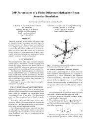
Ano<strong>the</strong>r major disadvantage is <strong>the</strong> possible instability ofrecursive filters. In general, <strong>the</strong> obtained solution has to bechecked so that all <strong>the</strong> poles of <strong>the</strong> filter remain within <strong>the</strong>unit circle in <strong>the</strong> z-domain, which makes real-time coefficientupdate difficult.Here we omit <strong>the</strong> problem of magnitude approximation byconsidering only <strong>the</strong> design of allpass filters, a special subclassof recursive filters. (For a report on fractional delay IIRfilter design, see [ 1 131.) Allpass filters have unity magnituderesponse in <strong>the</strong> whole frequency band by definition, whichmeans that one can concentrate on <strong>the</strong> approximation of <strong>the</strong>desired phase (or group delay, or phase delay) characteristics.This reduces <strong>the</strong> available degrees of freedom but also makes<strong>the</strong> design task much easier.The z transfer function of an Nth-order allpass filter is of<strong>the</strong> form!where <strong>the</strong> numerator polynomial is a mirrored version of <strong>the</strong>(supposedly stable) denominator D(z). The coefficients areassumed to be real-valued. The direct form I implementationof <strong>the</strong> allpass filter is shown in Fig. 9. The phase response of<strong>the</strong> allpass filter can be expressed as. Direct form I implementation of an Nth-order allpass filter.wherewheref N 7A=diag[O 1 ... N](69c)Naturally, for <strong>the</strong> phase delay it holds= arctan{$)where c and s are appropriate cosine and sine vectors asdefined in Eq. 30, and a is <strong>the</strong> coefficient vectorwith a0 = 1. The group delay of <strong>the</strong> allpass filter is related tothat of <strong>the</strong> denominator similarly to Eq. 65, orwhere <strong>the</strong> delay of <strong>the</strong> denominator can be expressed asUnfortunately, <strong>the</strong> phase, phase delay, and group delay areall related to <strong>the</strong> filter coefficients in a very nonlinear manner,as <strong>the</strong> above equations show. This means that one cannotexpect as simple design formulas for <strong>the</strong> allpass filter coefficientsas for FIR filters. Instead, one can almost exclusivelyfind only iterative optimization techniques for minimizationof traditional error criteria.In <strong>the</strong> following discussion, we shall review in greaterdetail only <strong>the</strong> simplest allpass design techniques that havesome potential for applications requiring real-time coefficientupdate. Among <strong>the</strong> above delay measures, <strong>the</strong> phase isperhaps <strong>the</strong> most suitable for least squared error design.Consequently, much of <strong>the</strong> following is based on <strong>the</strong> recentresults on least squares phase approximation presented in [60,63,53,77]. These schemes are easy to program and can alsobe modified for approximately equiripple phase error solutions,as well as for corresponding phase delay approximations,in contrast to many o<strong>the</strong>r methods that may be moredifficult to use.JANUARY 1996 <strong>IEEE</strong> SIGNAL PROCESSING MAGAZINE 47
Least Squares Design of Allpass Filters1) Approximate LS Phase Error DesignUsing <strong>the</strong> above notation, <strong>the</strong> phase error (deviation from aprescribed desired phase Oid(w)) can be expressed asequivalent to iteratively solving a set of N linear equations(Appendix C).The easiest way to eliminate <strong>the</strong> denominator is to neglectit, which effectively introduces coefficient-dependentweighting in <strong>the</strong> error measure and thus causes a bias from<strong>the</strong> true least squared error solution. In this case <strong>the</strong> matrix Pis solved aswhereand1p(0) = -[O, (0) + No]2(74)When approximating a noninteger delay D = N +. d, or-Dw= -(N + d>w, <strong>the</strong> last expression reduces to@,d(o)=codP(co) = --2(75)The term Nw is canceled out, since <strong>the</strong> average delay of <strong>the</strong>system is exactly N samples. In [60, 63, 53, 771, severaltechniques were developed to minimize <strong>the</strong> weighted leastsquared phase error, i.e., <strong>the</strong> measurewhere W(o) is a nonnegative weight function. By using linearapproximation for <strong>the</strong> arcus tangent function arctan(x) = x in<strong>the</strong> expression for <strong>the</strong> phase error (Eq. 71), a modified errormeasure can be expressed as(77)Twhere we define new matrices as Sp(w)= spsp and C(o) =cpcpT. If <strong>the</strong> coefficient vector a in <strong>the</strong> denominator wereknown and fixed, this error measure would be a quadraticform expressible aswhere a0 is <strong>the</strong> fixed coefficient vector and <strong>the</strong> matrix P isdefined in an obvious manner. When <strong>the</strong> matrix P is positivedefinite, <strong>the</strong>re exists a unique solution for <strong>the</strong> vector a whichminimizes <strong>the</strong> error measure (Eq. 78). The solution can befound, e.g., by <strong>the</strong> eigenfilter technique [116] which is(79)Due to <strong>the</strong> simple form of p(w), <strong>the</strong> integrals can be solvedin closed form, e.g., if W(w) is chosen piecewise constant.When it is set to W(w) = 1 in <strong>the</strong> approximation band oE[O,OLT], <strong>the</strong> elements of <strong>the</strong> P matrix are obtained as4p> k -n - J {cos[@- 1)ol- cos[(N - (k + 1 + d)ol }do0= 4a{sinc[a(k - Z)] - sinc[a(N - (k + 1 + d))]}k,E=1,2 ,..., L (80)The matrix is seen to have a Toeplitz-plus-Hankel structure.This approximation scheme offers an efficient way to solvefor <strong>the</strong> allpass coefficients, only requiring solution of <strong>the</strong> setof N equations. Using fast algorithms like <strong>the</strong> one proposedin [71], this matrix can be inverted in order of N2 arithmeticoperations instead of N' complexity required for inversion ofa general matrix.The bias from <strong>the</strong> least squares solution can be removedby employing an iterative algorithm such that <strong>the</strong> old coefficientsare used in <strong>the</strong> denominator for weighting, as originallyproposed in [60] and [63]. With this scheme, <strong>the</strong> matrix at <strong>the</strong>qth iteration isFor details, see [63] or [77]. As demonstrated in <strong>the</strong>sereferences, <strong>the</strong> algorithm typically converges to <strong>the</strong> desiredsolution although it cannot be guaranteed.Let us demonstrate both methods by approximating fractionaldelay with second and fifth-order allpass filters. Thephase delay curves obtained using <strong>the</strong> noniterative method(Q. 79) are shown in Figs. B la and b, respectively. Note thatwe show <strong>the</strong> phase delay responses for <strong>the</strong> entire range -0.5sd s0.5 since, unlike FIR filters, no symmetry relations holdfor allpass filters. The phase delay approximation appears to beworse at low frequencies. This is because <strong>the</strong> filter is designedby minimizing <strong>the</strong> phase enror but <strong>the</strong> phase delay (phase dividedby frequency) naturally yields large values when <strong>the</strong> frequencyis small. Fur<strong>the</strong>rmore, it was observed that <strong>the</strong> iterative method(Es. 81) produces essentially equivalent results so that, 111 contrastto phase equalizers [77], in FD filter design <strong>the</strong> noniterativemethod should be preferred in practice.2) LS Phase <strong>Delay</strong> Error Design of Allpass FiltersSince <strong>the</strong> phase delay is defined as <strong>the</strong> negative phase divided48 <strong>IEEE</strong> SIGNAL PROCESSING MAGAZINE JANUARY 1996