Physical Modeling of Plucked String Instruments with Application to ...
Physical Modeling of Plucked String Instruments with Application to ...
Physical Modeling of Plucked String Instruments with Application to ...

Create successful ePaper yourself
Turn your PDF publications into a flip-book with our unique Google optimized e-Paper software.
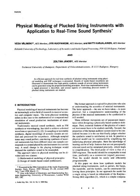
PAPERS<strong>Physical</strong> <strong>Modeling</strong> <strong>of</strong> <strong>Plucked</strong> <strong>String</strong> <strong>Instruments</strong> <strong>with</strong><strong>Application</strong> <strong>to</strong> Real-Time Sound Synthesis*VESA VALIMAKI**, AES Member, JYRI HUOPANIEMI, AES Member, and MA'rTI KARJALAINEN, AES MemberHelsinki University <strong>of</strong> Technology, Labora<strong>to</strong>ry <strong>of</strong> Acoustics and Audio Signal Processing, F/N-02/50 Espoo, FinlandANDZOLTA, N J.&.NOSY, AES MemberTechnical University <strong>of</strong> Budapest, Department <strong>of</strong> Telecommunications, H-I I 11 Budapest, HungaryAn efficient approach for real-time synthesis <strong>of</strong> plucked string instruments using physicalmodeling and DSP techniques is presented. Results <strong>of</strong> model-based resynthesis areillustrated <strong>to</strong> demonstrate that high-quality synthetic sounds <strong>of</strong> several string instrumentscan be generated using the proposed modeling principles. Real-time implementation usinga signal processor is described, and several aspects <strong>of</strong> controlling physical models <strong>of</strong>plucked string instruments are studied.0 INTRODUCTION The former approach is typical for physicists who aimat understanding the acoustics <strong>of</strong> musical instruments.<strong>Physical</strong> modeling <strong>of</strong> musical instruments has become The latter approach--the one we have taken--is morean increasingly active field <strong>of</strong> research in musical acous- practical, but a comprehensive understanding <strong>of</strong> thetics and computer music. The term physical modeling physics <strong>of</strong> the musical instruments <strong>to</strong> be synthesized isrefers in this case <strong>to</strong> the mathematical or computational still needed.simulation <strong>of</strong> sound production mechanisms <strong>of</strong> musi- Three different viewpoints are <strong>of</strong> paramount imporcalinstruments,tance when designinga physicallybased synthesistech-Traditionally musical sound synthesis, such as FM nique. First, essential features <strong>of</strong> the physics <strong>of</strong> a musisynthesisor waveshaping, has tried <strong>to</strong> achieve a desired cal instrument have <strong>to</strong> be studied carefully. Second, thewaveform or spectrum [1], [2]. In sampling or wavetable properties <strong>of</strong> the human audi<strong>to</strong>ry system need <strong>to</strong> be consynthesis,digital recordings <strong>of</strong> acoustic sounds are ed- sidered because it is the ear that finally judges whetherited and processed for resynthesis. Although sampled the synthetic sound is satisfac<strong>to</strong>ry or not. In practice a<strong>to</strong>nes may sound perfect, convincing synthesis <strong>of</strong> musi- physical model can be constructed by simplifying thecai instruments has been difficult since one sample cor- underlying physical principles. Here the knowledge <strong>of</strong>responds <strong>to</strong> a sound played by one instrument in a certain hearing can be <strong>of</strong> help: features that are not perceptuallyway. A small change in the playing technique would relevant need not be simulated precisely, which leadsdemand the synthetic sound <strong>to</strong> be resampled, <strong>to</strong> simplification. The third point <strong>of</strong> view is that <strong>of</strong> aThe approach taken in physical modeling can be dj- DSP engineer. The model should be computable in realvided in<strong>to</strong> two classes: time, preferably on a commercial (signal) processor.1) Mathematical modeling <strong>of</strong> physical principles Thus the model should be easily and efficiently2) Design <strong>of</strong> model-based sound synthesizers, programmable.In this paper we show how synthesis models for* Presented at the98th Convention <strong>of</strong> the Audio Engineering plucked string instruments, such as guitars, the banjo,Society, Paris, France, 1995 February 25-28; revised 1995 the mandolin, and the kantele, can be constructed fol-July 7 and 1996 March 13. lowing these principles. In our approach the model for** Also <strong>with</strong> School <strong>of</strong> Electronic and Manufacturing SystemsEngineering, University <strong>of</strong> Westminster, London W1M a single string is based on refinements <strong>of</strong> the Karplus-8JS, UK. Strong (KS) algorithm [3], which is a simple computa-J.AudioEng.Soc.,Vol.44,No.5,1996May 331i i i
VALIMAKI ETAL.PAPERStional technique for synthesizing plucked string sounds, modeling string instrumenis are discussed in Section 2.As reported by Jaffe and Smith [4], this algorithm is a Two basic models for a vibrating string and signal prosimplification<strong>of</strong> a physical model for a vibrating lossy cessing techniques such as Lagrange interpolation arestring, which is based on the solution <strong>of</strong> the wave equa- briefly described. The basic models are extended bytion. Later, Smith generalized this approach <strong>to</strong> what is introducing, for example, a dual-polarization stringnowadays called digital waveguide modeling [5]-[7]. model. The modeling <strong>of</strong> the body <strong>of</strong> a guitar is consid-We have further improved these principles in our model, ered from three points <strong>of</strong> view--digital filter approximasuchas <strong>with</strong> a continuously variable digital delay line tion, a principle based on commutativity <strong>of</strong> linear sysusingLagrange interpolation for adjusting the length <strong>of</strong> terns, and a hybrid where some resonances <strong>of</strong> the bodythe string [8] and a simple yet precisely tuned low,pass are explicitly modeled and a processed input signal infilter--calleda loop filter--<strong>to</strong> bring about the frequen- eludes the rest <strong>of</strong> the body response. Section 3 concency-dependentdamping <strong>of</strong> a string [9]. The model incor- trates on the analysis techniques that can be used forporates the influence <strong>of</strong> the body in an exceptionally estimating the values <strong>of</strong> the modelparameters. Examplesefficient way [7], [9]-[ 11]. Additions <strong>to</strong> the basic string <strong>of</strong> synthesis results are reported in Section 4. Real-timeand body model are discussed in order <strong>to</strong> include beat implementation techniques are considered in Section 5.effects inherent in string vibration and sympathetic ecu- In Section 6 control aspects <strong>of</strong> the physical models <strong>of</strong>plings between strings [4], [11], [12]. plucked string instruments are discussed. Finally, con-After the model structure has been designed, an esti- clusions are drawn and directions for future work aremation method is needed for calibrating the values <strong>of</strong> given in Section 7.the model parameters. A particular subproblem is theestimation <strong>of</strong> the coefficients <strong>of</strong> the loop filter. This I OVERVIEW OF PLUCKED STRINGproblem was first addressed by Smith in the early 1980s INSTRUMENTS[12], [13]. He studied several parametric methods formatching the loop filter and also proposed some nonpara- The his<strong>to</strong>ry <strong>of</strong> guitarlike plucked string instrumentsmetric methods, such as the use <strong>of</strong> deconvolution. In spans <strong>to</strong> antiquity. Cultural and geographical differences[14] a time-frequency representation was applied <strong>to</strong> the have led <strong>to</strong> the evolution <strong>of</strong> a large family <strong>of</strong> stringanalysis <strong>of</strong> musical sounds, and the loop filter was de- instruments over a long period <strong>of</strong> time. In this papersigned based on those data. In [15] the same approach we have concentrated on the analysis and model-basedwas used in the analysis, but instead <strong>of</strong> using the KS sound synthesis <strong>of</strong> six example cases <strong>of</strong> the pluckedmodel, a pair <strong>of</strong> poles was assigned <strong>to</strong> each sinusoidal string instrument family:component. The technique was applied <strong>to</strong> the synthesis 1) The modern classical nylon-string acoustic guitar<strong>of</strong> the piano, but was reported <strong>to</strong> have been tested for 2) The flat-<strong>to</strong>p steel-string acoustic guitarguitar<strong>to</strong>nesas well.3) TheelectricguitarWe have obtained pro<strong>to</strong>type frequency responses for 4) The banjothe loop filters by means <strong>of</strong> short-time Fourier analysis 5) The mandolinand envelope tracking <strong>of</strong> the harmonics. A first-order 6) The kanteleall-pole filter is matched <strong>to</strong> the analysis data using a All these string instruments exhibit some special charweightedleast-squares design. Smith has independently acteristics, which are <strong>to</strong> be taken in<strong>to</strong> account whendeveloped a very similar analysis method [16]. There- designing model-based sound synthesizers. The goal inafter the input signal for the model can be extracted this research was, however, not only <strong>to</strong> create soundfrom a recorded string instrument sound using inverse synthesis methods, but also <strong>to</strong> use physical modeling asfiltering. This approach has also been proposed in [12], a <strong>to</strong>ol in the research <strong>of</strong> different string instruments. A[1;4], [15]. The residual can be truncated or windowed, short overview <strong>of</strong> the string instruments featured in thisand the resulting short-duration sequence can be fed in<strong>to</strong> paper is given in this section. A more detailed analysisthe synthesis model <strong>to</strong> produce an approximation <strong>of</strong> the <strong>of</strong> the acoustics <strong>of</strong> some <strong>of</strong> these instruments can beoriginal signal. The parameters <strong>of</strong> the model can be found in [17], for example.modified, and yet a very natural sounding signal willresult. 1.1 Acoustic GuitarThis paper presents an overview <strong>of</strong> our recent work Analysis and modeling <strong>of</strong> the classical acoustic guitaron model-based sound synthesis <strong>of</strong>plucked string instru- has been presented in previous papers [8], [9], [11],ments. Our contribution has been <strong>to</strong> introduce high- [18], but asan extension <strong>to</strong> guitar modeling we measuredquality real-time synthesis for the acoustic guitar [8], and modeled the behavior <strong>of</strong> the steel-string acoustic[11] and for several other instruments. The work in- guitar. The main difference in the acoustics <strong>of</strong> theseeludes refinements <strong>of</strong> modeling techniques, such as frae- instruments is causedby two facts: 1) the material <strong>of</strong> thetional delay filtering, body modeling, estimation <strong>of</strong> the strings and 2) the plucking method. Steel-string guitarsmodel parameters, implementation techniques, and typically have crossed bracing in the soundboard due <strong>to</strong>methods for controlling the physical models, the higher tension <strong>of</strong> the strings [18]. The use <strong>of</strong> a plec:The organization <strong>of</strong> the paper is as follows. An over- trum instead <strong>of</strong> the finger as the excitation method resultsview <strong>of</strong> the plucked string instruments that are studied in a stronger pluck and a brighter <strong>to</strong>ne. These featuresin this paper is given in Section 1. The principles <strong>of</strong> can be taken in<strong>to</strong> account in a physical model.332 J. Audio Eng. Soc., Vol. 44, No. 5, 1996 May
PAPERS PHYSICAL MODELING OF PLUCKED STRING INSTRUMENTS<strong>of</strong> a banjo <strong>to</strong>ne is depicted in Fig. 2. The figure shows1.2 Electric Guitar the response after the first string was plucked <strong>with</strong> aThe main difference between acoustic and electric finger pick at a distance <strong>of</strong> 140 mm from the bridgeguitars is in the body <strong>of</strong> the guitar. The solid-body con- while other strings were damped. The resonances <strong>of</strong> thestruction, as the one we measured (Fender Stra<strong>to</strong>caster), body can be observed in the first 200 ms <strong>of</strong> the <strong>to</strong>ne.radiates very little sound from the body itself or the The impulse response <strong>of</strong> the soundboard has been foundstrings. Our model-based approach <strong>to</strong> the electric guitar <strong>to</strong> be quite long. This must be taken in<strong>to</strong> account in thedoes not cover the effects <strong>of</strong> magnetic pickups or nonlin- excitation signal <strong>of</strong> the synthesis model (see Sectionearly behaving amplifiers. Instead we focused on the 3.5). There is also two-stage decay behavior in the thirdbehavior <strong>of</strong> the string vibration in order <strong>to</strong> design a harmonic, which may result from mode summation orphysical model for the plain electric guitar,coupling effects.The three-dimensional plot in Fig. 1 exhibits thesound behavior <strong>of</strong> an electric guitar. The third string 1.5 Kantelewas plucked while other strings were damped. The neck The kantele is an ancient Finnish instrument that feapickupwas used for the recording. It can be seen that tures 5 <strong>to</strong> 40 strings. Fig. 3 shows the five-string kanteledue <strong>to</strong> the lack <strong>of</strong> body resonances the attack part is that has been used in the analysis. There are two specialvery well behaved. The decay <strong>of</strong> the harmonics is also characteristics in the kantele that are not found in othersmooth, that is, there is no nonlinear behavior. The sig- string instruments [20].nal was analyzed using the short-time Fourier transform 1) There are very strong beats in harmonic envelopes.(STFT) technique [19], which is discussed in Section 2) A prominent second harmonic exists due <strong>to</strong> longitu-3.2. dinalvibrationeffects.Both effects were found <strong>to</strong> be due <strong>to</strong> the unusual way1.3 Mandolin the strings have been terminated. The beats are gener-The mandolin is a string instrument used widely in ated when the horizontally and vertically polarized vifolkand bluegrass music in western countries. It features bration components are superimposed since there is aeight steel strings, which are tuned in four pairs. The clear difference in the effective string length in the twosound <strong>of</strong> the mandolin is brighter and decays faster than polarizations (see Section 2.6.2). This is due <strong>to</strong> the knotthat <strong>of</strong> the acoustic guitar. The pairs <strong>of</strong> equally tuned termination around the metal bar [Fig. 4(a)]. The strongstrings usually result in beating due <strong>to</strong> a minor difference second harmonic comes from the longitudinal tensionin the tuning. The STFT-based spectral analysis <strong>of</strong> one variation that bends the tuning peg [Fig. 4(b)] and radistring<strong>of</strong> the first string pair <strong>of</strong> the mandolin plucked utes from the soundboard proportionally <strong>to</strong> the square<strong>with</strong> a plectrum near the bridge is discussed in Section <strong>of</strong> the transversal string displacement.4.2 (see Fig. 27). The remaining strings, including the Fig. 5 shows a three-dimensional STFT analysis resul<strong>to</strong>ther string <strong>of</strong> the string pair, were carefully damped, <strong>of</strong> a kantele <strong>to</strong>ne. Note that the second harmonic is al-The quite rapid decay <strong>of</strong> the harmonics as well as a most 10 dB louder than the first harmonic in the attacklinear behavior <strong>of</strong> the strings can be observed, part, but it attenuates at a faster rate. Strong beating canbe observed in higher harmonics.1.4 BanjoThe banjo differs from the classical acoustic guitar 1.6 Instrument Measurementsmainly in the construction <strong>of</strong> the instrument body. The In order <strong>to</strong> find relevant analysis data for model-basedfive strings have been coupled via a metal bridge <strong>to</strong> a synthesis we conducted accurate and thorough measuredrumlikeresonating plate. The time-varying spectrum ments <strong>of</strong> the chosen string instruments. Pr<strong>of</strong>essional mu-.. .. ::.0 !·_ .... :=?o]o_-2001_-20 _0.5 1 0_ _ 01.5 1.52.5 _ 0.6Frequency (kHz) Time(s) Frequency (kHz)Time(s)Fig. 1. STFT analysis <strong>of</strong> electric guitar <strong>to</strong>ne. (Fender Stra<strong>to</strong>- Fig. 2. STFT analysis <strong>of</strong> banjo <strong>to</strong>ne. (Gibson Epiphone, firstcaster, third open string, fundamental frequency <strong>of</strong> 195 Hz.) open string, fundamental frequency 289 Hz.)J. Audio Eng. Soc., Vol. 44, No. 5, 1996 May 333
VALIM.a,KI ET AL.PAPERSsicians and high-quality instruments were used. The ba- <strong>of</strong> the string. The system is assumed <strong>to</strong> be linear, andsic measurements consisted <strong>of</strong> recording single notes thus all losses and other linear nonidealities may beplayed on each string at several fret positions. Both fin- lumped <strong>to</strong> the termination and excitation or pickupger picking and plectrum picking were used as the string points. This is because we are only interested in theexcitation method for instruments such as the electric output <strong>of</strong> the system and not in the amplitude values atguitar and the steel-string guitar. Typical playing styles, arbitrary points inside the system. Thus we can combinesuch as strumming, vibra<strong>to</strong>, and glissando, were also all the linear operations, namely, delays and filters, berecorded<strong>to</strong> obtain information for the control <strong>of</strong> the tween the input and output points (see, for example,models.[6]). The stringitselfcan thenbe describedas an idealAll measurements were carried out in a large anechoic lossless waveguide, which is a bidirectional discretechamberusing Briiel & Kjaer microphones and pream- time delay line [22], [6]. This system may be modeledplifiers. The measurement data were first s<strong>to</strong>red on a using a pair <strong>of</strong> delay lines and a pair <strong>of</strong> reflection filtersDAT recorder at 44.1-kHz sampling rate and 16-bit Rb(Z) and Rf(z), as depicted in Fig. 7. Each <strong>of</strong> thesequantization, giving a theoretical signal-<strong>to</strong>-noise ratio filters includes the reflection function <strong>of</strong> the correspond<strong>of</strong>about 96 dB. In the second phase the data were trans- ing termination <strong>of</strong> the string and the dissipative andferred on<strong>to</strong> a hard disk using the QuickSig s<strong>of</strong>tware dispersive contributiondue<strong>to</strong>thestringmaterial. A loss-[21 ] designed at the Labora<strong>to</strong>ry <strong>of</strong> Acoustics and Audio less delay line can be implemented computationally ef-Signal Processing <strong>of</strong> the Helsinki University <strong>of</strong> Tech- ficiently as a circular buffer where the data do not move,nology,bu<strong>to</strong>nly readandwritepointersareupdated.This mayreduce the computational load by several orders <strong>of</strong> mag-2 GENERAL MODEL FOR A STRING nitude as compared <strong>to</strong> a shift register, where the dataINSTRUMENTare actually moved.A string instrumentcan be dividedin<strong>to</strong> functionaliblocks, as illustrated in Fig. 6. Thesound sources<strong>of</strong> theinstrument are the strings, which have been connected <strong>to</strong>the bodyvia the bridgeand whichalso interact<strong>with</strong> ::eachother.Thesoundradiatesmainlythroughthebody. _The vibrating strings themselves act as dipole sources _ illand radiate sound inefficiently. First we concentrate onthestrings. 02.1 Basic Model for a Vibrating <strong>String</strong> lThe general solution <strong>of</strong> the wave equation for a vibrat- 2ing string is composed<strong>of</strong> two independentransversal 3 0.2 0wavestraveling in opposite directions(see, for example, 0.6 0.4[17]). At the string terminations the waves reflect back Frequency(kHz) 4 1 0.8 Time (s)<strong>with</strong> inverted polarity and form standing waves. The Fig. 5. STFT analysis <strong>of</strong> kantele <strong>to</strong>ne. (Fourth open string,losses in the system,damp the quasi-periodic vibration fundamental frequency 349 Hz.)MetalBar Five<strong>String</strong>s TuningPegsSoundboardlength = 60 cmFig. 3. Kantele, a traditional Finnish string instrument.fMetal BarTuning<strong>String</strong> <strong>String</strong> Metal_l_ Knot _ Peg---_ _-- Difference<strong>of</strong>effective Y////////////A Soundboardbending points <strong>of</strong> twovibrating modes(a)Fig. 4. <strong>String</strong> terminations <strong>of</strong> kantele. (a) Termination at metal bar, causing beat effect. (b) Termination at tuning peg, creatinglongitudinal nonlinearity.N(b)334 J. Audio Eng. Soc., Vol. 44, No. 5, 1996 May
PAPERSPHYSICAL MODELING OF PLUCKED STRING INSTRUMENTSAn efficient structure for a string model is obtained a similar comb filter [24].by commuting one <strong>of</strong> the delay lines <strong>with</strong> one reflection The fact that the finger or plectrum exciting the stringfilter. Then the delay lines may be combined in<strong>to</strong> a has a finite (nonzero) <strong>to</strong>uching width has been ignoreddouble-length line and the filters in<strong>to</strong> a single one that in this model, and it has been assumed that the excitationcan be expressed asacts at a single point. Widening the excitation point <strong>to</strong>an interval adds more low-pass filtering <strong>to</strong> the excitation.Hi(z) = Rb(z)Rf(z) . (1) We can bring about this effect using a low-order excitationfilter E(z), which models the dependence <strong>of</strong> theThe transfer function Hi(z ) is called the loop filter. This spectral tilt on the dynamic level <strong>of</strong> the pluck. Jaffeformulation is in practice equivalent <strong>to</strong> the model <strong>of</strong> Fig. and Smith [4] suggested that a one-pole digital filter7 when a comb filter P(z) is cascaded <strong>with</strong> the string be suitable for this purpose. Furthermore the complexmodel <strong>to</strong> cause the filtering effect due <strong>to</strong> the plucking interaction between the finger and the string has not beenposition [4]. The main difference is the delay between modeled. Instead, the excitation has been supposed <strong>to</strong>the excitation point and the output, but this is insignifi- be an event that can be modeled using linear operations.cant and can be compensated if necessary. This modified In reality, the finger may grab the string for a shortsystem, which we call a generalized KS model, is illus- while, causing nonlinear or linear, but time-varyingtrated in Fig. 8. A more detailed derivation and analysis interaction.are given in [23].The filter P(z) is called a plucking-point equalizer, 2.2 Length <strong>of</strong> <strong>String</strong>and its transfer function isThe effective delay length <strong>of</strong> the feedback loop in thestring model determines the fundamental frequency <strong>of</strong>P(z) = 1 + z -M Rf(z) (2) the output signal. The delay length (in samples) can becomputed aswhere Rf(z) is the reflection filter <strong>of</strong> one end <strong>of</strong> thestring model and M is the delay (in samples) between _ fs (3)the excitation points in the upper and lower lines <strong>of</strong> the L - fooriginal waveguide model (see Fig. 7). In practice Rf(z)in Eq. (2) need not be modeled very accurately since its where fs and fo are the sampling rate <strong>of</strong> the synthesismagnitude response is only slightly less than unity at allsystem and the desired fundamental frequency, respecfrequencies.In practice the most remarkable difference tively. In general L is a positive real number, and thusbetween direct and reflected excitation is the inverted implementation <strong>of</strong> the delay line calls for the use <strong>of</strong> aphase, and thus the filter can be replaced by a constant fractional delay filter, which we denote by F(z). It is amultiplier rf = -1 + e, where e is a small nonnegative phase equalizer that brings about a controllable fracrealnumber. The contribution <strong>of</strong> a pickup point in an tional delay. A first-order all-pass filter [4] and a thirdelectricguitar can be incorporated in<strong>to</strong> the model using order maximally flat FIR filter based on Lagrange interpolation[8] have been suggested as alternatives for theExcitationimplementation <strong>of</strong> the fractional-length delay line in astringmodel.I <strong>String</strong>1 _InteractionS,· _ Sound We used Lagrange interpolation for fractional delay<strong>String</strong>_ Body [Radiation. approximation. The filter coefficients h(n)<strong>of</strong> the Lagrangeinterpola<strong>to</strong>r are computed as (see, for example,/_/--i : [25])Fig. 6. Block diagram <strong>of</strong> general model for plucked string /vinstrument, h(n) = I'I D - kk=on- k'k_nExcitationn = 0,1,2 ..... N (4)Outputwhere N is the order <strong>of</strong> the FIR filter and D the desired. delay. Lagrange interpolationis equivalent <strong>to</strong> the maximallyflat approximation (at _o = 0) <strong>of</strong> band-limitedRf_lDelayLiiel 1_ vDelay_ interpolation. The approximation error (and its N deriva-Fig. 7. Waveguide model for vibrating lossy string, tives) is zero at o_ = 0 and negative everywhere else(unless d = 0), that is, the Lagrange interpola<strong>to</strong>r is alow-pass filter. The computational efficiencies <strong>of</strong> Nth-PluckPoint <strong>String</strong> order maximally fiat all-pass and FIR fractional delayInput Equalizer Model Output filters are compared in [26]. All-pass fractional delayx(n) P(z)_ _ y(n) filters are recursive and thus are prone <strong>to</strong> transient effectsFig. 8. Generalized Karplus-Strong model consisting <strong>of</strong> string when their delay is changed. In [27], [28] a new methodmodel S(z) cascaded <strong>with</strong> plucking-point equalizer P(z). was introduced <strong>to</strong> suppress the transients in time-varyingd. Audio Eng. Soc., Vol. 44, No. 5, 1996 May 335
VALIMAKI ETAL.PAPERSrecursive filters. This method was tested in the context the filter. For/-/l(Z) tO be a stable low-pass transfer func<strong>of</strong>string modeling [27]. An extensive review <strong>of</strong> digital tion, we require that - 1 < al < 0. The numera<strong>to</strong>r 1 +'filter approximations for fractional delay has been pre- a I scales the frequency response (divided by g) at 0 <strong>to</strong>sented by Laakso et al. [25]. unity, thus allowing control <strong>of</strong> the gain at co = 0 usingReal strings are more or less stiff so that the wave the coefficient g. We require that Igl_< 1.propagation is dispersive, that is, the <strong>to</strong>tal loop delay is Fig. 10 shows the magnitude response and the groupfrequency dependent. In principle, a single filter may delay <strong>of</strong> the loop filter HI(z) [Eq. (6)] <strong>with</strong> three differentimplement both the magnitude and the phase in the string values <strong>of</strong> coefficient a1. These values have been chosenmodel loop, but in practice it is easier <strong>to</strong> use three filters so that they represent cases found in practice. In this exam<strong>to</strong>control the three parts separately-- a linear-phase all- ple g = 0.99. (A change in g merely shifts the magnitudepass approximation F(z)<strong>to</strong> control the fundamental fre- response curve vertically.) Note that the group delay <strong>of</strong>quency, the loop filter Hi(z) <strong>to</strong> control the magnitude the loop filter is very small in all three cases.response, and an all-pass filter D (z) <strong>to</strong> adjust the frequen- Fig. 11 shows the impulse response <strong>of</strong> the string modelcy-dependent overall phase delay. See [29], [30] for a S(z) <strong>with</strong> the three loop filters <strong>of</strong> Fig. 10. Here the lengthdiscussion on the implementation <strong>of</strong> dispersive waveguidemodels using all-pass filters. For low strings, especiallyor crucial on the <strong>to</strong> piano the timbre [31], <strong>of</strong> [32], sound dispersivity synthesis. isFor important higher xp(n) '_'ri_ )_Ht(z_ Il L y(n)strings the dispersivity is relatively small. In mostplucked string instruments the effect due <strong>to</strong> dispersion Fig. 9. Block diagram <strong>of</strong> the string model S(z). F(z)--FIR orcan be neglected and the filter D(z) may be left out <strong>of</strong> all-pass-type fractional delay filter; Hl(z)--loo p filter.the model.To conclude our discussion on the frequency depen- i' 'al:-o00, _dence <strong>of</strong> the string length, let us express L((o) by means 41=---¢_i<strong>of</strong>L(co) the three = L I filters + 'tH(CO) discussed, + 'TF(00 ) "{- 'rD(la) ) (5) _0.95i _'0'9 tai_085'0 0.05 0:l 0.15 0'.2 0.25 0'.3 0.35 0.4 0.45 0.5where L[ is the integer number <strong>of</strong> unit delays in the·delay N.... lized Frequencyline, and Xn(CO),xr(co)m, and 'rD(m)are the phase delays(a)<strong>of</strong> the loop filter Hi(z), the fractional delay filter F(z), _______ . , ..,_and the dispersion filter D(z), respectively. Fig. 9 illus- 0.052.3trateSLoopthe In the original implementationFilter KS model <strong>of</strong> the thestring loop model filter Hl(z S(z). ) is a _0_-0o5........{_l_ -- -- _'"'"_ _ !ltwo-tap averager which is easy <strong>to</strong> implement <strong>with</strong>out Normalized Frequency----__i_alal =-0.01= -0.001' -0 0.05 0.1 0.15 0.2 0.25 0.3 0.35 0.4 0.45 0.5multiplications [3]. This simple filter, however, cannot (b)match the frequency-dependent damping <strong>of</strong> a physical Fig. 10. Magnitude response and group delay <strong>of</strong> one-pole loopstring. We feel that an FIR filter is not suited <strong>to</strong> this filter for three different values <strong>of</strong> a I. g = 0.99 in all cases.purpose since its order should be rather high <strong>to</strong> matchthe desired characteristics. Instead we suggest the useal = -0.001, g = 0.99, L = 19o a,m ,owpass.,terforsimu,ati. 'ILIILL Li III1I thcharacteristics <strong>of</strong> a physical string. The same decision ?was made in [12]. From [17], [33] it can be concluded _0.5that a second- or third-order all-pole filter could be suita- < 0_10 100 260 300 400 560 600 700 800 900 1000ble for a loop filter. It is important <strong>to</strong> use the simplest Sample Indexsatisfying loop filte r since one such filter is needed for 41=-0.ol.g=o.99. L=19static filter, but its coefficients should be changed as a _0_tll 1the function model<strong>of</strong> <strong>of</strong> theach string string.Also, length and other loop playing filteris param- not a < o/tit i ].,j '_ i 'eters. This is easiest <strong>to</strong> achieve using a low-order IIR 0 100 200 300 400 500 600 700 800 900 1000· Sample Indexfilter. We found that a reasonable approximation mayal = -O.O5,g =0.99, L = 19be obtainedusinga first-orderall-polefilter, i .........1 + a I (6) _0.5
PAPERS PHYSICAL MODELING OF PLUCKED STRING INSTRUMENTS<strong>of</strong> the delay line is L = 19. It is seen that the impulse tic guitar, respectively. The impulse response can beresponse decays more rapidly as the magnitude <strong>of</strong> al seen <strong>to</strong> be long enough so that the temporal envelope canincreases,beassumed<strong>to</strong> be perceptuallyimportant.Thesituationiscomparable <strong>to</strong> the perception <strong>of</strong> reverberation in a small2.4 <strong>Modeling</strong> the Body room. This implies that a digital filter approximationFrom the viewpoint <strong>of</strong> signal processing, the body <strong>of</strong> should not be designed exclusively based on magnitudetheacoustic guitar and the transfer function from the response criteria. The spectral envelope seen in Fig. 13 isbridge <strong>to</strong> a specific direction may be considered as a relatively flat, but there are a large number <strong>of</strong> resonanceshigh-order linear filter. A set <strong>of</strong> transfer functions would starting from the lowest resonance around 100 Hz.be needed <strong>to</strong> simulate the directivity pattem <strong>of</strong> a string We have studied several digital filter approximationsinstrument [34]. In most physical models only one transfer for modeling the body <strong>of</strong> the acoustic guitar [18]. Anfunction has been included. This simplified approach simu- FIR filter model <strong>of</strong> th6 body response must be at leastlates the radiation <strong>of</strong> the sound <strong>to</strong> one point in front <strong>of</strong> the 50 <strong>to</strong> 100 ms long (more than 1000 taps) <strong>to</strong> yield goodsound hole <strong>of</strong> the string instrument. This kind <strong>of</strong> model synthetic sound. Linear prediction (LPC) analysis sugwillthus at best produce a sound reminiscent <strong>of</strong> a recording gests an all-pole filter model <strong>of</strong> order 500 or more. Both<strong>of</strong> a musical instrument in a relatively anechoic room. In <strong>of</strong> these are computationally <strong>to</strong>o expensive for real-timeSection 2.5 we discuss different methods <strong>to</strong> incorporate implementation using a single DSP processor. We alsodirectivity characteristics in<strong>to</strong> physical models, designed reduced-order IIR filters that approximate theThe transfer function from the bridge <strong>to</strong> the listener frequency resolution <strong>of</strong> the human audi<strong>to</strong>ry system, butcan be measured approximately by exciting the bridge even these did not reduce the computational load enough<strong>with</strong> an impulse hammer and registering the radiated <strong>with</strong>out audible degradation <strong>of</strong> the sound quality. A moresound. Figs. 12 and 13 show the impulse response and detailed discussion <strong>of</strong> the body modeling problem isthe magnitude spectrum <strong>of</strong> the body <strong>of</strong> a classical acous- given elsewhere [23], [35].To overcome the inherently heavy computational load<strong>of</strong> the filter-based body models a novel method wasinvented [7], [9]-[ 11]. Let us consider the string instru-0_ ment model <strong>of</strong> Fig. 14(a). The output signal y(n) <strong>of</strong> thissystem can be expressed as0.60.4 y(n) = e(n) * h(n) * b(n) (7).g$. 02 where the asterisk denotes the operation <strong>of</strong> linear discrete
VALIMAKI ET AL. PAPERSe(n) and b(n) can be combined, as shown in Fig. 14(b). cessing point <strong>of</strong> view and as good as possible from theThe signal x(n) is then used as the input <strong>to</strong> the general- perceptual point <strong>of</strong> view. In earlier studies we have conizedKS string model. The combination <strong>of</strong> the excitation sidered three strategies [34], [37]:signal and the impulse response <strong>of</strong> the body is motivated 1) Directional filteringby the fact that then the body need not be modeled 2) Set <strong>of</strong> elementary sourcesexplicitly during real-time synthesis. The signal x(n) 3) Direction-dependent excitation.combining the excitation and the body response can be A direction-dependent digital filter may be attachedestimated by precomputing it based on some model, by <strong>to</strong> each path from the source <strong>to</strong> the listener. Moving andmeasuring it somehow, or by inverse filtering a digital rotating sources can be modeled by changing the filterrecording <strong>of</strong> an instrument, as will be discussed in Sec- parameters <strong>of</strong> the paths in a proper way (for example,tion 3.5.theLeslieeffect<strong>of</strong> a rotatingloudspeakercan be simu-We may develop the model further by explicitly mod- lated). The directional filtering method was studied foreling the excitation signal. The first step <strong>to</strong>ward this the acoustic guitar. We came <strong>to</strong> the conclusion that evendirection is <strong>to</strong> extract the most prominent resonances <strong>of</strong> first- or second-order directivity filters give useful rethebody, measure their central frequencies and Q val- suits, thus leading <strong>to</strong> an efficient implementation.ues, and design a second-order all-pole filter <strong>to</strong> represent Fig. 15 depicts the modeling <strong>of</strong> direction-dependenteach resonance. These resonances must then be removed radiation <strong>of</strong> the acoustic guitar (in the horizontal plane)from the excitation signal, for example, by using nar- relative <strong>to</strong> the main-axis radiation. Shown in the figurerow-band linear-phase FIR filters,are magnitude spectra for second-order IIR filters at azi-We have successfully extracted the two lowest reso- muth angles <strong>of</strong> 90, 135, and 180°. The reference magninances<strong>of</strong> the body <strong>of</strong> an acoustic guitar. The main ad- tude spectrum at 0 ° is assumed <strong>to</strong> be flat. The lowvantage<strong>of</strong> this approach is that the residual signal <strong>with</strong> pass characteristic is noticeably increased as the relativethe low-frequency high-Q resonances removed decays angle is greater. The measurement was carried out bymore rapidly than the original one. As a consequence, exciting the bridge <strong>of</strong> the instrument using an impulsea shorter excitation signal can be used, and the memory hammer and registering the reference response at 0° andrequirements for the model-based synthesizer are low- the related response in various directions. The measuredered. Also, the Q values and the central frequencies <strong>of</strong> reference and the directional response were fitted sepathelowest resonances are now parameterized and thus rately <strong>with</strong> first- or second-order AR models. A simpleindependently controllable,division <strong>of</strong> the models was performed <strong>to</strong> obtain thepole-zero directivity filter.2.5 <strong>Modeling</strong> Directional Properties <strong>of</strong> <strong>String</strong> Fig. 16(a) shows the transfer function measured at<strong>Instruments</strong> azimuth angles <strong>of</strong> 0 and 180 °. Fig. 16(b) gives the re-The directional characteristics <strong>of</strong> musical instrument sponse at 0° filtered <strong>with</strong> a first-order IIR directivitysound radiation are <strong>of</strong> interest in several applications filter and the actual measured response at 180 ° azimuth.using model-based sound synthesis. From the scientific Note that the spectral slopes are nearly the same, as waspoint <strong>of</strong> view the physical modeling approach serves as expected. In this example the transfer function <strong>of</strong> thea flexible <strong>to</strong>ol for analysis and simulation <strong>of</strong> the directiv- directional filter isity <strong>of</strong> the instruments. Directional characteristics mustbe taken in<strong>to</strong> account when model-based sound synthesismethods are used for sound generation in room acousticsR (z) - bo + biz- l1 + a]z- _ (10)simulation and other virtual reality applications [34],[36].<strong>Plucked</strong> string instruments exhibit complex sound ra- o ____
PAPERS PHYSICAL MODELING OF PLUCKED STRING INSTRUMENTSwhere the coefficient values are bo = 0.2041, bI = in parallel as there are directions <strong>to</strong> be included. This-0.1431, and a_ = -0.4389. limits the number <strong>of</strong> simulated directions, for example,When zooming <strong>to</strong> the details <strong>of</strong> the lowest resonance <strong>to</strong> the six main directions <strong>of</strong> the Cartesian coordinatemodes we notice, as described in [17], that the individual system. Even then this approach is computationallymodes behave differently. To model such details, a rela- very inefficient.tively high-order directional filter is needed. It is im- The foregoing considerations as well as our experiportant<strong>to</strong> notice that due <strong>to</strong> the critical-band frequency ments have shown that the directional filtering techniqueresolution, an audi<strong>to</strong>ry smoothing may be applied <strong>to</strong> the is normally the most practical one. A first- or secondresponsesbefore directional filter estimation. This helps order filter approximation is <strong>of</strong>ten a satisfac<strong>to</strong>ry solution<strong>to</strong> reduce the order <strong>of</strong> the filter,in a real-time implementation.The use <strong>of</strong> elementary sources is based on the idea thatthe radiation pattern <strong>of</strong> an instrument is approximated by 2.6 Extensions <strong>of</strong> the <strong>String</strong> Modela small number <strong>of</strong> monopoles or dipoles. In general the The string model can be extended in several ways <strong>to</strong>method is computationally expensive if a large number more carefully simulate a vibrating physical string. In<strong>of</strong> paths <strong>to</strong> the receiver is needed since each new elemen- the following we present three examples. For a moretary source adds a new set <strong>of</strong> path filters, detailed discussion, see [23].In the case <strong>of</strong> commutative excitation [such as theplucked string instrument model shown in Fig. 14(b)] 2.6.1 Sympathetic Vibrationsthe directivity filtering may be included in the composite Sympathetic vibration is a phenomenon where someexcitation in a way similar <strong>to</strong> the inclusion <strong>of</strong> the (early) modes <strong>of</strong> a string are excited by the vibration <strong>of</strong> otherroom response [7]. The problem <strong>with</strong> this method is that strings primarily due <strong>to</strong> couplings through the bridge.the same number <strong>of</strong> string model instances are <strong>to</strong> be run It can be simulated by feeding a small fraction <strong>of</strong> theoutput <strong>of</strong> each string model <strong>to</strong> the other strings [4], [11].This simplified technique does not take in<strong>to</strong> account thefrequency dependence <strong>of</strong> sympathetic couplings, but itmostill addsrealism<strong>to</strong> the synthetic<strong>to</strong>nes.Sincethereis90 feedbackviaallstrings,thevalues<strong>of</strong>thecouplingcoefficientsmust be carefully adjusted so that they are smalls0enoughnot <strong>to</strong> makethe systemunstable.Anotherand70 theoreticallymorecorrectway<strong>to</strong>incorporatethesympatheticvibrations is <strong>to</strong> represent the bridge by a separate60 filterthatis common<strong>to</strong> allstringsin a waveguidemodel<strong>of</strong> an instrument [7]. This approach adds, however, c0m-50 putationalcomplexity<strong>to</strong> the overallmodel.40 2.6.2 Dual-Polarization <strong>String</strong> Model30 <strong>Physical</strong>stringsvibratein boththe verticaland the0 I 2 3 4 5 6 7 8 9 10 horizontal directions. If the effective length <strong>of</strong> the stringFreque,cy(mz) is not the same in the two polarization planes, the mixing(a)<strong>of</strong> the two subsignals <strong>of</strong> slightly different frequenciesil°Ilcreatesbeatsin thesound.Thishasbeenfound<strong>to</strong> bean]00H[]_[_ll.I _'importantfeature in the sound quality<strong>of</strong> the kantele[20], wheretheexplanationforthis effectis thepeculiar9°_'_[[1__ _a A_, Fi't_redr_fer_nce. 180° way in which the strings have been terminated. In otherstring instruments, however, the effective length in the80 two directions can differ due <strong>to</strong> changes in the driving-7o point impedance <strong>of</strong> the bridge. This can be incorporatedin the model by using two basic string models <strong>with</strong>60 different L for each string [11]. Fig. 17 illustrates acomplete model, including dual-polarization string,5owavetableexcitation,andsympatheticcouplings.40 In thecase<strong>of</strong> themandolin,beatingis causedbythefact that there are four pairs <strong>of</strong> equally tuned strings.30 This can be modeled using two separate string models0 _ 2 3 4 5 6 7 s 9 10 for each pair.Frequency (Hz)(b) 2.6.3 NonlinearitiesFig. 16. <strong>Modeling</strong> <strong>of</strong> guitar sound radiation <strong>with</strong> first-order In strings the polarization <strong>of</strong> vibration may changeIIR filters. (a) Transfer functions measured at azimuth angles0 and 180°. (b) Response at 0° filtered <strong>with</strong> directivity filter continuously in a complex manner since there are weakand measuredtransfer function at 180°. nonlinearities transferring energy between modes andd. Audio Eng. Soc., Vol. 44, No. 5, 1996 May 339m · · ....
V]_LIM_.KI ETAL.PAPERSpolarizations. In the kantele, bending the tuning peg at where y(n) is the signal <strong>to</strong> be analyzed and w(n) is aone end <strong>of</strong> the strings has been shown <strong>to</strong> induce nonlin- window function (such as the Hamming window). Anearity due <strong>to</strong> longitudinal forces [20]. This effect has estimate for the pitch is obtained by searching for thebeen simulated successfully in the following way. The maximum <strong>of</strong> _bk(m)for each k.delay line signal is squared, then filtered using a leaky Typical pitch con<strong>to</strong>urs <strong>of</strong> a guitar and a kantele <strong>to</strong>neintegra<strong>to</strong>r, and the result is added <strong>to</strong> the output <strong>of</strong> the are shown in Fig. 18. The con<strong>to</strong>urs have been smoothedstring model. This procedure boosts the even harmonics using a three-point running median filter [40]. In both<strong>of</strong> the signal, cases the pitch decreases <strong>with</strong> time and approaches aIn [38] a passive nonlinear filter was PrOPosed for constant value after about 0.5 s. In the kantele the deproducingeffects similar <strong>to</strong> mode coupling in string in- crease <strong>of</strong> the fundamental frequency is quite substantial..struments. A first-order digital all-pass filter is attached The problem now is <strong>to</strong> determine the best estimate fo<strong>to</strong> the end <strong>of</strong> the delay line <strong>of</strong> the string model. The · for the fundamental frequency in a perceptual sense. Incoefficient <strong>of</strong> the all-pass filter depends on the sign <strong>of</strong> practice a good solution is <strong>to</strong> use the average pitch valuethe delay line signal. Another alternative is <strong>to</strong> use a after some 500 ms as the nominal value, since it isvariable delay based on a Lagrange interpola<strong>to</strong>r FIR important <strong>to</strong> have a reliable pitch estimate <strong>to</strong>ward thefilter. This technique was found <strong>to</strong> be suitable for pro- end <strong>of</strong> the note. This improves the quality <strong>of</strong> syntheducingsynthetic signals that exhibit time-varying behav- sized <strong>to</strong>nes.ior in their decay parts. Once the estimate .f0 for the fundamental frequencyhas been chosen, the effective length L <strong>of</strong> the delay line3 CALIBRATION OF MODEL PARAMETERS can be computed asThe synthesis system includes three parts that corn- fspletely determine the character <strong>of</strong> the synthetic sound-- L =for-. (13)the string model, the plucking-point equalizer, and theinput sequence. This implies that <strong>to</strong> calibrate the model 250[ , j<strong>to</strong> some particular instrument it is needed <strong>to</strong> estimatethe values for the length <strong>of</strong> the delay line L, the coeffi-_249.8I__cients <strong>of</strong> the loop filter Hi(z), the delay M and the param-_249'6I_249.4 Ieter signalrfx(n). <strong>of</strong> the In plucking-point this section the parameter equalizer, estimation and the input procedures_ 249'2Ithat will extract these values are described. 249_ o'.l o'.2 o13 0'.4 o15 0.6(a)3.1 Estimation <strong>of</strong> the Delay Line Length LThe delay length L (in samples) determines the funda- 409 1mental frequency fo <strong>of</strong> the synthetic signal according <strong>to</strong>Eq. (3) so that_4o8fo = (11) _--406 01.! 0'.2 0'.3 01.4 0.5 0.6Time(s)wherefs is the sample rate. For pitch detection we have (b)used a well-known method based on the au<strong>to</strong>correlation Fig. 18. Fluctuation <strong>of</strong> fundamental frequency. (a) Steel-stringfunction. The short-term or windowed au<strong>to</strong>correlation gmtar <strong>to</strong>ne. (b) Kantele <strong>to</strong>ne.functio n is defined as [39]1N-1_k(m) = _ _'=o[y(n + k)w(n)y(n + k + m)w(n + m)] , 0 _
PAPERSPHYSICALMODELINGOFPLUCKEDSTRINGINSTRUMENTSWhen the loop filter has also been designed, we can Spectral peak detection results in a sequence <strong>of</strong> magnisubtractits phase delay from L and define the nominal tude and frequency pairs for each harmonic. The sefractionaldelay Lr as quence <strong>of</strong> magnitude values for one harmonic is calledthe envelope curve <strong>of</strong> that harmonic. A straight line isLr = L - 'tH(C00)- floor[L - %/(COo)] (14) matched <strong>to</strong> each envelope curve on a decibel scale, sinceideally the magnitude <strong>of</strong> every harmonic should decaywhere cb0 = 2_rjeo. The delay Lr is used as the desired exponentially, that is, linearly on a logarithmic scale.delay in the design <strong>of</strong> the fractional delay filter F(z). In Measurements show that this idealized case is rarely metpractice the phase delay <strong>of</strong> this filter can be expressed in practice, and many different kinds <strong>of</strong> deviations areas xF(Co) = Mr + Lr, where positive integer Mr is the common. It is possible <strong>to</strong> decrease the error in fit byintegral part <strong>of</strong> the phase delay that depends on the order starting it at the maximum <strong>of</strong> the envelope curve [43]<strong>of</strong> the fractional delay filter and Lr is the fractional part. and by terminating it before the data get mixed <strong>with</strong> thenoise floor, such as after the decay <strong>of</strong> about 40 dB. As3.2 Measuring the Frequency-Dependent a result, a collection <strong>of</strong> slopes I_k for k = 1, 2.....Damping N h is obtained (see Fig. 19). The corresponding loopNext we discuss how <strong>to</strong> measure damping <strong>of</strong> a string gain <strong>of</strong> the string model at the harmonic frequencies isas a function <strong>of</strong> frequency. As discussed in Section 2.1, computed asall losses, including the reflection at the two ends <strong>of</strong> thestring, are incorporated in the loop filter Hi(z). In order Gk = 10_Aa°H , k = 1,2 ..... N h (17)<strong>to</strong> design a loop filter we need <strong>to</strong> estimate the dampingfac<strong>to</strong>rs at the harmonic frequencies <strong>of</strong> the sound signal, where [3k are the slopes <strong>of</strong> the envelopes and H is theThis is achieved using the short-time Fourier transform hop size. The sequence Gk determines the pro<strong>to</strong>type(STFT) [19] and tracking the amplitude <strong>of</strong> each har- magnitude response <strong>of</strong> the loop filter Hl(o_) at the harmonic,monic frequencies o_k, k = 1, 2 ..... N h, as illustratedThe STFT <strong>of</strong> y(n) is a sequence <strong>of</strong>'discrete Fourier in Fig. 20.transforms (DFT) defined as The desired phase response for Hl(_) can be determinedbased on the frequency estimates <strong>of</strong> the harmon-N- _ ics. We do not, however, try <strong>to</strong> match the phase responseYm(k)= n=O _ w(n)y(n + mH)e -j'°_ , m = 0, 1, 2,... <strong>of</strong> the filter. There are two principal reasons for this.(15) First we believe that it is much more important <strong>to</strong> matchthe time constants <strong>of</strong> the partials <strong>of</strong> the synthetic sound<strong>with</strong> than the frequencies <strong>of</strong> the partials, since rather smalldeviations from harmonic frequencies occur in the case2_rk <strong>of</strong> plucked string instruments. In case we wanted <strong>to</strong>,r_°k - N ' k = 0, 1, 2 ..... N - 1 ' (16) resynthesize strongly inharmonic <strong>to</strong>nes, the phase response<strong>of</strong> the loop filter should be considered. The secwhereN is the length <strong>of</strong> the DFT, w(n) is a window ond reason is that as we want <strong>to</strong> use a low-order loopfunction, and H is the hop size or time advance (in filter, the complex approximation <strong>of</strong> the frequency re-'samples) per frame. In practice we compute each DFT sponse would not be very successful. Thus we restrictusing the FFT algorithm. To obtain a suitable compro- ourselves <strong>to</strong> magnitude approximation only in the loopmise between time and frequency resolution, we use a filter design.window length <strong>of</strong> four times the period length <strong>of</strong> thesignal. The overlap <strong>of</strong> the windows is 50%, implyingthat H is 0.5 times the window length. We apply exces- . . ' .....sive zero padding by filling the signal buffer <strong>with</strong> zeros __ _ ' 2 '<strong>to</strong> reach N = 4096 in order <strong>to</strong> increase the resolutioning <strong>to</strong> harmonics can be found from the magnitude spectrumfirst finding the nearest local minimum at both -_cbetween sides <strong>of</strong> an these assumed two local maximum. minima The is assumed largest magnitude <strong>to</strong> be the _-_5 ._ _---_____ __inthefrequencydomain.by harmonic peak. The estimates Thespectralpeakscorrespond- for the frequency and :_ _ _._.. 3magnitude <strong>of</strong> the peak are fine-tuned by applying para- -2cbolic interpolation around the local maximum and solvingfor the value and location <strong>of</strong> the maximum <strong>of</strong> this -2_interpolating function (see [41] or [42] for details). Thenumber <strong>of</strong> harmonics <strong>to</strong> be detected is typically Nh < -3c 0.05 01! 0.15 012 0.25 0'.3 0.35 0'.4 0.45 0.520 (for the acoustic guitar). The STFT analysis is applied Time(s)<strong>to</strong> the portion <strong>of</strong> the signal that starts before the attack Fig. 19. Straight-line fits (dotted lines) <strong>of</strong> envelope curvesand ends after some 0.5-1 s after the attack. (solid lines) <strong>of</strong> six lowest harmonics <strong>of</strong> electric guitar <strong>to</strong>ne.J.AudioEng.Soc.,Vol.44,No.5, 1996May 341
VALIMAKI ET AL. PAPERS3.3 Loop Filter DesignLet us denote the numera<strong>to</strong>r <strong>of</strong> Eq. (6) byIt is known that our hearing is sensitive <strong>to</strong> the change A = g(1 + al) (20)<strong>of</strong> decay rate <strong>of</strong> a sinusoid, and in practice we measurethe time constant <strong>of</strong> some 20 lowest harmonics <strong>with</strong> the and HI(<strong>to</strong>) <strong>with</strong> the numera<strong>to</strong>r removed byintent <strong>of</strong> matching the frequency response <strong>of</strong> the loopfilterfilter,Hl(Z)it is<strong>to</strong>clearthosethatdata.thereSincearewemoreuse arestrictionsfirst-order loopthan//l(<strong>to</strong>) - HI(t°)A (21)unknowns in this problem, and only an approximatesolution is possible. Then Eq. (18) can be rewritten asIn principle the loop filter should be designed basedon an audi<strong>to</strong>ry criterion, but since that would be compli- tq- 1cated, we decided <strong>to</strong> use weighted least-squares design. E = _ W(GD[IAPi(%)I - Gk]2 . (22)k=0The error function <strong>to</strong> be minimized in the magnitudeonlyapproximation can be defined as The gain g <strong>of</strong> the loop filter at low frequencies canNh-l be chosen based on the loop gain values <strong>of</strong> the lowestE = ___ W(GO[lHl(<strong>to</strong>OI - Gk]2 (18) harmonics. In many cases it is good enough <strong>to</strong> set g =k=0 Go, whereas sometimes the average <strong>of</strong> two or three lowestloop gain values gives a better result.where N h is the number <strong>of</strong> frequency points where the The value for the coefficient a I that minimizes E canloop gain Gk is approximated, % = kO0 are the central be found by differentiating Eq. (22) <strong>with</strong> respect <strong>to</strong> a 1.frequencies <strong>of</strong> the N h lowest harmonics, and W(Gk) is This yieldsa nonnegative error weighting function. It is reasonableltO choose a weighting function W_ Ut _ that gives a largerOENh - 1- 2A0 _'. W(GO01[-/1(%)1'' [IAo[/l(<strong>to</strong>0l- Gk].weight <strong>to</strong> the errorsdecaying harmonicsin the time constants <strong>of</strong> the slowlysince our hearing tends <strong>to</strong> focus onOa1 k=o Oaltheirdecay.A candidateforsucha weightingfunctionis (23)Nh-lBy substituting Eqs. (6) and (19), we can writeOE _ 2A° _ Aocos <strong>to</strong>k(1 + alcos%) -3 - Gkcos <strong>to</strong>n(1 + alcos%) -l (24)Oal k=o 1 -- GkThe aim is now <strong>to</strong> find the zero <strong>of</strong> this function. In1 practice we find a near-optimal solution in the followingW(GO - 1 - Gk' (19) way. The value <strong>of</strong> the derivative is evaluated, and dependingon the sign <strong>of</strong> the result, a I is changed by asmall increment, the derivative is evaluated again, andWe require that 0 _< Gk < 1 for all k, which is a physisoon. After the derivative has reached a very smallcally reasonable assumption since the system <strong>to</strong> be modvalue,the iteration is terminated and the final value foreled is passive and stable.a1 is used in the synthesis model. We have verifiedthe convergence <strong>of</strong> this design procedure in practice by....... analyzing signals generated using the synthesis model.0.995 data yields the same filter parameters--<strong>with</strong>in numericalaccuracy--as were used in the synthesis. Also analysis '9 Theloopfilterthatwasdesignedbasedonthe the°'99I / I [ T"_ _-- _ match <strong>with</strong> natural <strong>to</strong>nes has been found <strong>to</strong> be satisfac-·S['_°'985[ I '"'-( I_<strong>to</strong>ry in many cases. Fig. 20 illustrates the loop filter094r I I I I I design fora typical kantele <strong>to</strong>ne.0.975 It iswellunders<strong>to</strong>odthatwhena stringisput<strong>to</strong>vibra-90.97 tion by plucking it, the sound signal will lack those harmoniesthat have a node at the plucking point (see, for.0'9651 example, [17]). However, in general the string is not0 96_/ ' 015 '_'.s ' _' _'._ , _ , _ plucked exactly at the node <strong>of</strong> any <strong>of</strong> the lowest harmon-' . _.5 2 2.5 3 3.5 ics, and since the amplitude <strong>of</strong> the higher harmonics isFrequency(kHz)Fig. 20. Loop filter design for kantele. Circles--loop gains considerably small anyway, it is not possible <strong>to</strong> accu-G2 at harmonic frequencies; solid line--the magnitude re- rately detect the plucking point by simply searching forsponse [H_(z)l2. the lacking harmonics in the magnitude spectrum. An-342 d. Audio Eng. Soc., Vol. 44, No. 5, 1996 May
PAPERS PHYSICAL MODELING OF PLUCKED STRING INSTRUMENTSother practical problem may occur because <strong>of</strong> nonlinear using a time-varying inverse filter, which cancels thebehavior <strong>of</strong> the string. Namely, the amplitude <strong>of</strong> vibra- impulse response <strong>of</strong> the string. This filter can be' detion<strong>of</strong> a weak harmonic can gain energy from other signed based on the STFT analysis discussed above.modes so that its amplitude begins <strong>to</strong> rise, reaching a However, satisfac<strong>to</strong>ry results are obtained when usingmaximum about 100 ms after the attack, and then begins carefully chosen <strong>to</strong>nes that behave well, that is, there<strong>to</strong> decay [44]. This can <strong>of</strong>ten be seen in the analysis <strong>of</strong> are no strong nonlinear effects nor beating present. Fig.harmonic envelopes <strong>of</strong> the guitar. For these reasons we 21 shows the spectrum <strong>of</strong> a mandolin <strong>to</strong>ne and the magnibelievethat a more comprehensive understanding <strong>of</strong> the tude response <strong>of</strong> the inverse filter. The magnitude speceffect<strong>of</strong> the plucking point can be achieved by studying trum <strong>of</strong> the residual (the result <strong>of</strong> inverse filtering) isthe time-domain behavior <strong>of</strong> the string in terms <strong>of</strong> the illustrated in Fig. 22. Note that in this case the harmonicsshort-time au<strong>to</strong>correlation function. A frequency- have been canceled quite accurately.domain technique for estimating the plucking point hasbeen reported by Bradley et al. [45]. 4 SYNTHESIS OF PLUCKED STRINGSEstimation <strong>of</strong> the plucking position is an inherentlydifficult problem since a recorded <strong>to</strong>ne can include con- The residual signals resulting from the analysis andtributions <strong>of</strong> several delays <strong>of</strong> approximately the same inverse filtering <strong>of</strong> an original string instrument <strong>to</strong>ne canmagnitude, such as early reflections from objects near be directly applied as the excitation <strong>to</strong> the string model,the player, the floor, the ceiling, or a wall. To minimize as described in Sections 2 and 3. The synthesis procedurethe effect <strong>of</strong> these additional fac<strong>to</strong>rs, we suggest per- is carried out in the following way.forming the analysis <strong>of</strong> <strong>to</strong>nes recorded in an anechoic 1) Obtain the residual signal by inverse filtering,chamber. 2) Window the first 100 ms <strong>of</strong> the residual signalIt is, however, not absolutely manda<strong>to</strong>ry <strong>to</strong> estimate using, for example, the right half <strong>of</strong> a Hammingand model the effect <strong>of</strong> the plucking position. Its contri- window.bution can be left in the excitation signal obtained usinginverse filtering, which is described in the followingsection.03.5 Inverse Filteringfiltering, that is, filtering the signal y (n) which is now _assumed <strong>to</strong> be the output <strong>of</strong> the model <strong>with</strong> the in- _-20 ·hein utsignalxn _,o...!1transfer function <strong>of</strong> the string model shown in Fig. 9canbeexpressedas 301S(z) = 1 - z -L_F(z)HI(z)' (25)vetted transfer function S-'(z) <strong>of</strong> the string model. The _ii [If S(z) had zeros outside the unit circle, the inverse filter - ' ' 9 1S-l(z) would be unstable. In that case, inverse filtering Fr*q.... y(mz)would not yield an acceptable result. Fortunately this is Fig. 21. Magnitude spectrum <strong>of</strong> mandolin <strong>to</strong>ne (solid line) andmagnitude response <strong>of</strong> inverse filter (dotted line).not a problem in practice, as can be seen by substitutingEq. (6) in<strong>to</strong> Eq. (25). Inverting this equation yieldsS-i(2)=l-[-alz-1--lg(l+alz-+ alz -1 1)z-L' F(z) (26) -it-10This technique is simple <strong>to</strong> apply, but since the order -_5<strong>of</strong> the loop filter is low, the harmonics are not canceled 4_20very accurately using the inverse filter S-_(z). The re- vsulting x(n) may suffer from high-frequency noise. The _-25low-order loop filter was chosen primarily since it is then -30efficient <strong>to</strong> implement the synthesis model. However,inverse filtering is an <strong>of</strong>f-line procedure, where accuracy -35is much more important than efficiency. We could thus -40design a higher order filter <strong>to</strong> be used in the inverse -45filtering (see for example, [12] or [15]).Another deficiency <strong>of</strong> the inverse filtering technique I 2 3 4 5 6 7 8 9 l0is that it does not take in<strong>to</strong> account the nonlinear effects Frequency (kHz)<strong>of</strong> the physical strings. This can be accounted for by Fig. 22. Magnitude spectrum <strong>of</strong> inverse filtered mandolin <strong>to</strong>ne.d. Audio Eng. Soc., Vol. 44, No. 5, 1996 May 343
VALIMAKIETAL.PAPERS3) Use the truncated signal as the excitation <strong>to</strong> the The analysis and synthesis results <strong>of</strong> the steel-stringstring model, acoustic guitar were similar <strong>to</strong> those <strong>of</strong> the nylon-string4) Run the string model using the parameters derived acoustic guitar. The use <strong>of</strong> the plectrum instead <strong>of</strong> thefrom the analysis, finger in the string excitation results in a different-sound-The original and the synthesized signals presented and ing residual signal, but the string model can be the samediscussed in this chapter are downloadable as sound files for both instruments.(AIFF, WAV, and MPEG-1 layer II formats) using theWorld Wide Web [46]. 4.2 MandolinThe analysis and resynthesis <strong>of</strong> the mandolin are illus-4.1 Guitars trated in Figs. 25 and 26. We notice that windowing and'From the analysis and synthesis results <strong>of</strong> the electric truncation <strong>of</strong> the residual signal have only minor effects,guitar shown in Figs. 23 and 24 it can be seen that the shortening the decay <strong>of</strong> the lowest body resonances. Thelength <strong>of</strong> the residual signal used in resynthesis can be resynthesized <strong>to</strong>ne in Fig. 26(b) has been calculated usingreduced <strong>to</strong> about 50 ms <strong>with</strong>out any significant loss <strong>of</strong> the first 100 ms <strong>of</strong> the residual and a single-polarizationinformation. This is due <strong>to</strong> the lack <strong>of</strong> body resonances, string model. The original mandolin signal shows a slightThe resulting sound is quite similar <strong>to</strong> that <strong>of</strong> the basic beating effect after the transient part, whereas the resynthe-KS model excited <strong>with</strong> an impulse. It is clear that in this sized <strong>to</strong>ne has an exponentially decaying behavior. It is,case physical modeling principles should be extended <strong>to</strong> however, almost impossible '<strong>to</strong> distinguish the syntheticvarious magnetic pickup combinations and amplifiers, <strong>to</strong>ne from the original one by ear. Using a dual-polarization0.5 0. -i-_o. i'ii. .-1 0.05 0.1 ' 0.15 0.2 0.25 I 0.! 0.]5 012 0.25(a)(a)0._-o,-o_i i i-10 0.05 0.1 0.15 012 0.25 0.05 0.1 0.115 012 0.25Time(s)(b)Fig. 23. (a) Electric guitar <strong>to</strong>ne. (b) Residual signal after in- Fig. 25. (a) Mandolin <strong>to</strong>ne. (b) Residual signal after inverseverse filtering, filtering.Time(s)(b)0.5 0.50 *. 0-0.5 -0.-10 0.05 ' 0i 1 0.15 ' 0' 2 0.25 '0 0.05 0.1 0.15 0.2 0.25(a)(a)I , , , , ,-0.0'5I0 . '_/i0.250 0.05 0.1 0.15 0.2 0.25 0 0.05 0.1 O.15 0.2Time(s)(b)Fig. 24. (a) Truncated residual signal. (b) Resynthesized elec- Fig. 26. (a) Truncated residual signal. (b) Resynthesized mantricguitar<strong>to</strong>ne.dolin<strong>to</strong>ne.Time(s)(b)344 J.AudioEng.Soc.,Vol.44, No.5, 1996May
PAPERS PHYSICAL MODELING OF PLUCKED STRING INSTRUMENTSstring model <strong>with</strong> a very small beating effect would result attack part <strong>of</strong> the signal. The distinctive sound <strong>of</strong> thein an even more natural <strong>to</strong>ne. Figs. 27 and 28 depict the banjo is retained in the residual signal after inverse filtemporalcharacteristics <strong>of</strong> the six lowest harmonics <strong>of</strong> the tering. Figs. 31 and 32 depict the results <strong>of</strong> the analysisoriginal and the synthetic mandolin <strong>to</strong>nes, respectively. It and the synthesis.can be clearly seen that the transient part is identical in In this example some <strong>of</strong> the harmonics <strong>of</strong> the originalboth plots. The decay <strong>of</strong> the harmonics is very similar but signal decay much faster than the first harmonic. Thenot identical, synthesis model <strong>with</strong> a first-order loop filter is not able<strong>to</strong> catch this phenomenon. For this reason the decay4.3 Kantele rate <strong>of</strong> some harmonics is <strong>to</strong>o slow in the resynthesizedThe use <strong>of</strong> the dual-polarization string model is essen- signal. This can be seen by comparing Figs. 31 andtial in the case <strong>of</strong> the kantele. As shown in Fig. 5, there 32. Apart from this slight difference, the overall soundis significant beating in the signal, which clearly affects quality <strong>of</strong> the synthetic signal is excellent.the sound quality. <strong>Modeling</strong> this dual-polarization behavioris quite straightforward <strong>with</strong> two separate string 5 REAL-TIME IMPLEMENTATION ON A SIGNALmodels, as was discussed in Section 2.6.2. Figs. 29 and PROCESSOR30 depict the analysis and synthesis results for a kantele<strong>to</strong>ne. A dual-polarization string model was used for the The real-time synthesis models were implemented ussynthesis.The nonlinear characteristics <strong>of</strong> the kantele ing a Texas <strong>Instruments</strong> TMS320C30 floating-point sighavebeen resynthesized according <strong>to</strong> the principles pre- nal processor. This processor is capable <strong>of</strong> executing asented in Section 2.6.3. maximum <strong>of</strong> 30 million floating-point operations per4.4 Banjo _ .....In the analysis <strong>of</strong> the banjo we experienced that most os<strong>of</strong> the characteristics <strong>of</strong> a banjo <strong>to</strong>ne are included in the0':4L_-lO,..' '· · 0 0.05 O.I 0.15 0.2 0.25'(a)._-30, 0.50 I.............. )AJ_........ Jt i I.-0.5[1 ':: -lo 0.85 oh 0.'15 012 0.252 Time (s)o(b)3 0.3 o.2 o.t Fig. 29. (a) Originalkantele<strong>to</strong>ne.(b) Residualsignalafter0.4 inverse filtering.Frequency (kHz) 4 0.5Time (s)Fig. 27. STFT analysis <strong>of</strong> mandolin <strong>to</strong>ne. (Gibson model A,first open single string, fundamental frequency 649 Hz.)0.i.f.. .!.: : :. -0_,0, '" -_ 0.85 d, o._s d2 o.ls-20, ". (a)0-30-50_0" 0.1 ' -0.520 - I 0.05 0]1 0.15 0.2 0.253 0.2 0.1 Time(s)0.30.4 (b)Frequency(kHz) 4 0.5Time (s)Fig. 30. (a)Truncated residualsignal. (b) Resynthesizedkan-Fig. 28. STFr analysis <strong>of</strong> resynthesized mandolin <strong>to</strong>ne. tele <strong>to</strong>ne.J. Audio Eng, Soc., Vol. 44, No. 5, 1996 May 345· m - -
IIVALIM_.KI ET AL.PAPERSsecond (30 MFLOPS, 15 MIPS). Our experience was, PC platforms. We use commercially available DSP boards.however, that this limit cannot be reached in practice, Our developments include using a multiprocessor enexceptin special cases when register, pipeline, and mem- vironment for running several instruments in parallelory conflicts can be <strong>to</strong>tally avoided. Our hand-optimized or for a more detailed simulation <strong>of</strong> the instruments,assembly code taking up about 110 instructions per output including nonlinear effects. We have experimented <strong>with</strong>sample for a single string was able <strong>to</strong> run six strings in a system containing two TMS320C31 processors, whichreal time <strong>with</strong> a sampling rate <strong>of</strong> 22 kHz, including host are less expensive and slightly reduced versions <strong>of</strong> thecommunication and parameter calculation. However, this TMS320C30, and we have built a more advanced systemwas found <strong>to</strong> be adequate for producing excellent plucked using TMS320C40 floating-point processors, which supstringsounds since there is not much energy in the spec- port multiprocessing in hardware [36].tram <strong>of</strong> these signals above 10 kHz.The implementation <strong>of</strong> plucked string synthesis on aAn overview <strong>of</strong> the s<strong>of</strong>tware and hardware environ- signal processor follows the principles <strong>of</strong> Fig. 9. Eachment for the real-time implementation <strong>of</strong> physical mod- substring (single polarization) consists <strong>of</strong> a ring bufferels is given in Fig. 33. Programs written in the QuickC30 delay line <strong>with</strong> third-order Lagrange interpolation (forenvironment [47] can be run on different hardware plat- fine-tuning) and a loop filter. Table look-up is used forforms <strong>with</strong>out modification. All hardware-dependent de- computing the interpola<strong>to</strong>r coefficients from pitch infortailsare hidden from the application by the use <strong>of</strong> spe- mation. Also the loop filter parameters have been tablecialized macros and functions. So far the QuickC30 coded. <strong>String</strong> excitations are read from wavetables thatsystem has been implemented on the Macin<strong>to</strong>sh and the have been constructed using inverse filtering techniques.Most control parameters are MIDI-like, that is, theycover a number range from 0 <strong>to</strong> 127. The computation<strong>of</strong> the model parameters, such as the delay and loop-as possible by table look-up since computationally expensivedivisions, logarithms, and exponents are other--o._ {). filter wise parameters needed. (For andcontrol excitation parameters, filtering, see is done also as Section much6.)" 0;5 or, 015 0'2 ,,25(a)The updating <strong>of</strong> model parametersis executedevery1 ms, which has been found fast enough in most transientsandtransitions.Thereducedparameterupdaterateo.5llllis suchas necessary<strong>to</strong> inthecase<strong>of</strong> keepthecomputationalcost guitarsynthesis. lowenough,5.1 Multirate <strong>String</strong> Model-0 Astringinstrumen<strong>to</strong>ne,likemostnaturalsignals,is0 005 o l 0'15 0'2 o25 a low-pass signal whose spectrum varies through timeTimeCs) SO that high-frequency components are damped faster(b)than low-frequencycomponents. Thus it would be ad-Fig. 31. (a) Original banjo <strong>to</strong>ne. (b) Residual signal after vantageous <strong>to</strong> design a multirate synthesis model whereinversefiltering,the input sequenceis fed in at a high samplingrate, butwhere the delay line.and the loop filter Hi(z) would runat a rate considerablylower.Thisidea has alsobeenmentioned in Smith [48, p. 50]. As a result, the attack0.5-0.5-I 0.05 0.1 0,15 r 02 , (}.25(a)DSP· -0.50.1MIDI controllers0.05 0.1 Time (s) 0.15 0'2 0.25 other MIDI applications _ _,(b)Fig. 32. (a) Truncated residual signal. (b) Resynthesized Fig. 33. S<strong>of</strong>tware and hardware environment for real-timebanjo<strong>to</strong>ne.implementation <strong>of</strong>physicalmodels.346 J. Audio Eng. Soc., Vol. 44, No. 5, 1996 MayU
V_,LIMAKIET AL.PAPERSsign the lowest string that can play the given pitch <strong>to</strong> While pitch is a well-defined property--in practice itthe note. A more elaborate method would be allocating corresponds roughly <strong>to</strong> the fundamental frequency <strong>of</strong>the strings so that the movement <strong>of</strong> the left hand would a note--expression cannot be uniquely defined. Still,be minimized. This can be accomplished easily if it is everyone "feels" what it means. Although these feelingspossible <strong>to</strong> preprocess the score. However, this latter are not necessarily the same, it can be agreed that amethod cannot be used <strong>with</strong> real-time control. As a eom- low value <strong>of</strong> expression means something like colorless,promise, nearly real-time control can be used [49]. passing, or s<strong>of</strong>t, whereas a high value can be interpretedas emotional, bright, emphasized, or loud. Moreover6.2 MIDI and Intelligent Synthesis Control the interpretation <strong>of</strong> the expression seems <strong>to</strong> be closelyMIDI has several caveats when used <strong>with</strong> complex related <strong>to</strong> the performance style. The realization <strong>of</strong> thissound synthesis such as physical modeling. In principle, led <strong>to</strong> the idea <strong>of</strong> combining the timbre and the mappingone could use many different controller messages for <strong>of</strong> pitch and expression <strong>to</strong> the actual synthesis paramdetailedcontrol over the synthesis. This approach, how- eters in<strong>to</strong> performance styles, like classical guitar, bluesever, has severe drawbacks. It is rather difficult <strong>to</strong> con- guitar, or flamenco guitar.trol many parameters manually and there are many pa- Reducing the control parameters <strong>to</strong> only two drastirametercombinations that simply do not make a sound, cally reduces the complexity <strong>of</strong> the control interface,Another problem is that MIDI glues <strong>to</strong>gether the pitch and it still allows human interaction. For more detailedset and note triggering in<strong>to</strong> a single "note on" message, control, the attack part <strong>of</strong> the notes, which carries theThese events are clearly separated in time on the variable most important indication <strong>of</strong> the playing technique,source instruments. Therefore when such sound is syn- could be controlled separately. On the keyboard thesethesized, these control events should be separated <strong>to</strong> expression controls could be assigned <strong>to</strong> the after<strong>to</strong>uchcreate natural note transitions,and key velocity, respectively.In spite <strong>of</strong> these problems it would be convenient <strong>to</strong>use existing MIDI equipment <strong>with</strong> new synthesizers. 6.4 Overview <strong>of</strong> OuickMuslcWe suggest a new approach for controlling complex QuickMusic is the musical sound synthesis controlsynthesis <strong>with</strong> MIDI: let the control interface--which package <strong>of</strong> the QuickSig system (see Fig. 33) and ismaps the performance events in<strong>to</strong> control events--be written entirely in Common Lisp/CLOS. It contains amore intelligent. By intelligent we mean that it should platform-independent sequencer, which uses a Lisp-synworkreasonably, even if not all details are given explic- tax musical notation and a real-time MIDI interface.itly. The missing information can be deducted from a Originally the package had been developed under Macinknowledgebase created by studying the performance <strong>to</strong>sh Common Lisp (MCL). Recently we have ported ittechniques <strong>of</strong> the given instrument and analyzing the (<strong>to</strong>gether <strong>with</strong> other parts <strong>of</strong> the QuickSig environment)impact <strong>of</strong> different playing techniques on the sound, <strong>to</strong> the PC platform under Allegro Common Lisp forThis approach has an additional advantage--it is much Windows.easier <strong>to</strong> play an intelligent instrument than a complexbut dumb synthesizer.6.5 The Lisp SequencerThe Lisp sequencer can be used <strong>to</strong> quickly create test6.3 Simplifying the Control Problem note sequences or even demo pieces. For describing aThe usual timbre space has three independent param- score a Lisp-like musical notation is used, allowing easyeters--pitch, level, and timbre. These parameters are parameterizing <strong>of</strong> the' individual notes by keyword pa<strong>to</strong>ogeneral for controlling specialized synthesizers such rameters. The sequencer is object oriented and thus casasthose based on physical models. However, during the ily expandable.performance <strong>of</strong> a musical piece the timbre will probably The score is processed in four phases--parsing, pernotexit a bounded subspace stretched by the possible forming, exploding, and playing. During the parse phasesounds <strong>of</strong>, for example, a given acoustic guitar <strong>with</strong>in a high-level object description <strong>of</strong> the note sequence isa given performance style. Naturally there will be differ- generated. The perform phase was included <strong>to</strong> allowent subspaces for different instruments and performance au<strong>to</strong>matic performance <strong>of</strong> the piece using performancestyles, but the main point is that the performer can rules. This part has not been exploited so far. The exchoosethe adequate subspace a priori. It may also be plode phase generates (usually several)low-level controlnecessary <strong>to</strong> allow shifting from one subspace in<strong>to</strong> an- events from the notes. Finally the built-in schedulerother during the performance if the conditions change plays the piece on the DSP hardware in real time.substantially.For moving around inside one <strong>of</strong> these subspaces we 6.6 MIDI Control Interfacecan use fewer parameters--pitch and something we call The most important elements <strong>of</strong> QuickMusic are the"expression." Choosing pitch as the primary parameter different control interfaces that map the input MIDIis motivated by our interest in traditional Western music, events (such as key on/<strong>of</strong>f, wheel movement) <strong>to</strong> thewhich is entirely based on the twelve-<strong>to</strong>ne scale and actual synthesis parameters. They were added <strong>to</strong> allowwhere the most important property <strong>of</strong> a note is its pitch, interactive performance and easy experimenting <strong>with</strong> re-In our approach all internal parameter calculations are al-time synthesis algorithms. As an additional advantagebased on the desired pitch, <strong>of</strong> using MIDI, an external MIDI sequencer can be used348 J. Audio Eng. Soc., Vol. 44, No. 5, 1996 May
PAPERSPHYSICAL MODELING OF PLUCKED STRING INSTRUMENTS<strong>to</strong> record and replay performances. Unfortunately this technique cannot be used in real-A platform-independent MIDI message dispatch sys- time performance.tem has been built on <strong>to</strong>p <strong>of</strong> the low-level interface.Message dispatching is accomplished au<strong>to</strong>matically by 6.7.3 Special Control Modesthe CLOS method dispatching mechanism, since the ge- We have experimented <strong>with</strong> advanced control modesneric method process-midi-message is specialized on for the guitar synthesizer. They help in creating a naturalboth the instrument class and the type <strong>of</strong> MIDI message, sounding guitar performance using a standard MIDI key-The MIDI control interfaces are implemented as differ- board. Two basic styles have been investigated--soloent instrumentclasses,playingand strumming.Solo Guitar: Playing a guitar solo is slightly different6.7 Operating Modes from using the MIDI mono mode. On the guitar a soloThe interactivity <strong>of</strong> Lisp makes it easy <strong>to</strong> experiment is usually played on several strings. Therefore au<strong>to</strong>matic<strong>with</strong> different control strategies. We have developed sev- string allocation is used. In the solo mode all specialeral different modes, partly <strong>to</strong> overcome the limitations playing techniques that will be discussed later areposed by MIDI itself or <strong>to</strong> facilitate playing "guitarlike" available.on a normal keyboard. The keyboard, <strong>of</strong> course, by no Rhythm Guitar: One difficulty <strong>of</strong> playing voiced guitarmeans can replace a guitar controller (just as much as chords correctly on the keyboard is the relatively largethe synthesizer does not replace the acoustic guitar), but internote separation <strong>of</strong> the chord members. To reducethese specialized modes help getting the most out <strong>of</strong> the this problem we have implemented an intelligent chordsynthesizer in terms <strong>of</strong> fidelity and ease <strong>of</strong> playing, recognizer, allowing simplified chord fingering. The algorithmtries <strong>to</strong> fit different chords <strong>to</strong> the depressed keys6.7.1 Standard MIDI Modes and the most probable chord is selected (such as A, Am,In order <strong>to</strong> be able <strong>to</strong> use existing MIDI files se- A7). It is then revoiced for the guitar using look-upquenced by others we have implemented the standard tables. When alternative voicings are possible (as inMIDI control modes as an option, most cases), the position <strong>of</strong> the previously played chordMono Mode: The MIDI mono mode is <strong>of</strong>ten used <strong>with</strong> can be used <strong>to</strong> select the chord in the closest position.MIDI guitar controllers <strong>to</strong> send the performance data The player can influence the selection <strong>of</strong> the chord posionseparate MIDI channels for each string. This mode tion by using different octaves <strong>of</strong> the keyboard.simplifies the MIDI implementation in the receiver. Eachperformancestylecanhaveitsownset<strong>of</strong>chords,There is one sound genera<strong>to</strong>r per channel, and there is which is based on the most <strong>of</strong>ten used chords <strong>of</strong> theno need for voice allocation. Ambiguous pitches, which given style. Furthermore, styles can contain chords thatcould be played on different strings, do not cause a use only the upper strings, leaving the lower strings freeproblem. Pitch bend can be used individually on differ- for playing bass notes, as in folk or Latin-Americanent strings <strong>with</strong>out affecting other notes, styles. In this case the bass notes can be played onWhile the mono mode is perfectly suited for the MIDI another part <strong>of</strong> the keyboard using the keyboard splitguitar, it is difficult <strong>to</strong> use it <strong>with</strong> a keyboard. Although mode, or they can be played by using a special notekeyboardsplit could be used <strong>to</strong> send data on different triggering mode. The notes are not triggered immedichannels,playing chords is quite difficult if not impossi- ately by fingering a chord, but separate keys--one keyblethis way.per string--are used <strong>to</strong>pluckthestringsafterward.ThisPoly Mode: In the poly mode the data for all strings technique can be used for playing nice arpeggios as well.are received on a single MIDI channel, and the control With these techniques many common guitar styles caninterface has <strong>to</strong> assign the notes <strong>to</strong> available sound gener- be played from the keyboard <strong>with</strong> little effort.a<strong>to</strong>rs. There is a potential problem <strong>with</strong> instruments <strong>of</strong>the variable source type. Assigning a different genera<strong>to</strong>r 6.8 Mixing Control Modes<strong>to</strong> a new note will not result in a correct transition. <strong>String</strong> It is possible <strong>to</strong> switch between control modes duringallocation is necessary for most string instruments, performance. This feature helps <strong>to</strong> play chordal solosinterleaved <strong>with</strong> short runs. It is also possible <strong>to</strong> split6.7.2 Smart MIDI Modes the keyboard and define different control modes overSmart MIDI modes are enhanced MIDI modes. While the two ranges.they accept MIDI events intended for normal use, theytry <strong>to</strong> add more details <strong>to</strong> the sound, such as by splitting 6.9 Special Techniquesthe "note on" <strong>to</strong> separate pitch set and note start events. In this section we discuss some special playing tech-Since setting the pitch happens before starting the note, niques not available on keyboard instruments. Thesethis can only be achieved by delaying the start <strong>of</strong> a techniques can be simulated <strong>with</strong> our intelligent connoteby a small amount. Other enhancements, such as trol interfaces.au<strong>to</strong>matic fret noise generation, need even more delay.Allowing a relatively large (0.5-1 s) constant pro- 6.9.1 Hammer-On and Puli-Offcessing delay helps in both cases. When the synthesizer Hammer-on and pull-<strong>of</strong>f are left-hand techniques thatis driven by a sequence, the delay can be compensated a guitar player sometimes uses <strong>to</strong> pluck a note. By strikbyadvancing the given track by the amount <strong>of</strong> delay, lng a finger against a fret, one can set the string in<strong>to</strong>J. Audio Eno. Soc., Vol. 44, No. 5, 1996 May 349i I II
VALIM_.KI ET AL.PAPERSmotion <strong>with</strong>out plucking it <strong>with</strong> the right hand. This decreasing the pressure on the frets <strong>with</strong> the left handtechnique can be used if the pitch <strong>of</strong> the hammered note (a technique <strong>of</strong>ten used in country or beat strummingis higher than the previous one on the same string. It is styles). Both techniques result in a quick damping <strong>of</strong>convenient for playing grace notes or fast passages. A the string. Right-hand muting <strong>of</strong>ten causes an extrasimilar technique is fret tapping, used by many electric sound when the palm hits the guitar body and the strings.guitarists, which allows playing very fast solos <strong>with</strong> both In contrast, left-hand muting usually does not introducehands on the fret board,extra noise, and it is <strong>of</strong>ten only partial, damping thePull-<strong>of</strong>f is a complementary technique, which results higher harmonics more than the fundamental.in a lower pitch. The left-hand finger releases the fret In our system muting can be accomplished by steppingused for the previous note, and at the same time it plucks on the' sustain pedal. The same effect can be assignedthe string by pulling it a little sideways. Advanced play- <strong>to</strong> a key. Partial muting--an <strong>of</strong>ten used effect <strong>with</strong> theers can play complete melodies <strong>with</strong>out using their right electric guitar--can be controlled <strong>with</strong> the expressionhandatall.pedal.When hammer-on recognition is on, the control interfaceassumes that the new "note on" that is played on 6,9.5 Changing Pluck Positionan already sounding string should be a hammer-on or a Plucking a string close <strong>to</strong> the bridge causes a s<strong>of</strong>ter,pull-<strong>of</strong>f, depending on the direction <strong>of</strong> the pitch change, brighter, and sharper <strong>to</strong>ne, while plucking <strong>to</strong>ward theIn the solo mode this can be accomplished by hitting neck makes a louder, mellower sound. Because <strong>of</strong> thethe next key before the previous one has been released position <strong>of</strong> the right-hand fingers, the low strings are(similarly <strong>to</strong> the fingered portamen<strong>to</strong> in the mono mode usually plucked further away from the bridge than theon many synthesizers). In the poly mode the string allo- higher ones. Moreover, varying the pluck position hascation algorithm suggests a hammer-on or pull-<strong>of</strong>f when an artistic effect by changing the overall timbre. On theit cannot allocate a new string <strong>with</strong> the given configura- keyboard the position can optionally be mapped <strong>to</strong> thetion. In every case, releasing a key before the next one key velocity (s<strong>of</strong>ter <strong>to</strong>uch will move it closer <strong>to</strong> theis pressed ensures that the new note will be plucked, bridge) or <strong>to</strong> the modulation wheel.6.9.2 Tremolo Picking 6.10 Parameter CalculationTremolo picking is a fast up-down alternate stroke The calculation <strong>of</strong> the actual synthesis parameters--plucking technique, typically used <strong>with</strong> the mandolin, delay-line length, loop filter coefficients, and fractionalthe bouzouki, or the balalaika. The string is not damped delay filter coefficients--is based on two-dimensionalmanually between the individual strokes, but a new look-up tables indexed by the desired pitch and exprespluckwill au<strong>to</strong>matically damp the previous note, creat- sion values. We are experimenting <strong>with</strong> an alternativelng a characteristic sound. This effect can be somehow method that employs a neural network for implementingimitated on a normal keyboard by fast repetition <strong>of</strong> a the nonlinear mapping functions. Both methods use pakey.However, this way it is not possible <strong>to</strong> tell the rameters derived from actual performances recorded prestrokedirection, which is important in double-stringed viously and analyzed by a computer.instruments. Moreover, the standard interpretation <strong>of</strong>, "note on" and "note <strong>of</strong>f" would cut away the note in 7 CONCLUSIONS AND FURTHER WORKbetween the repetitions, which sounds very unnatural.Though the sustain pedal could be used <strong>to</strong> avoid this A physically based modeling technique for pluckedartifact, as a result the new notes would be triggered string instruments has been developed aiming at high<strong>with</strong>outdamping the old ones, thus making a ringing quality real-time sound synthesis. The model for a vieffectinstead <strong>of</strong> the tremolo picking, brating string used in this method is based on a general-The use <strong>of</strong> the special string excitation keys (discussed ized KS model, which is constructed <strong>of</strong> digital delayunder Rhythm Guitar) au<strong>to</strong>matically results in a correct lines and linear filters. Many approaches <strong>to</strong> the modelingtransition <strong>to</strong> the new note. Furthermore there is a sepa- <strong>of</strong> the body <strong>of</strong> string instruments have been studied, andrate tremolo key which, when pressed, plucks the last particularly successful results in terms <strong>of</strong> efficiency andnote again <strong>with</strong> a different pluck sequence, correspond- sound quality have been obtained by using an inverselng <strong>to</strong> the opposite stroke direction, filtered input signal.The parameter values <strong>of</strong> the synthesis model can be6.9.3 Fingered Vibra<strong>to</strong> calibrated based on the analysis <strong>of</strong> acoustic signals, andAu<strong>to</strong>matic vibra<strong>to</strong> sounds usually rather unnatural. It thus the model can imitate the sound <strong>of</strong> a real instrument.can be replaced by mapping the keyboard after<strong>to</strong>uch <strong>to</strong> The analysis consists <strong>of</strong> pitch detection and short-time"pitch bend up" <strong>with</strong> a small pitch bend range. This way Fourier analysis. Estimates for the length <strong>of</strong> the delayexpressive vibra<strong>to</strong>s can be played easily by hand. line <strong>of</strong> the string model and the coefficients <strong>of</strong> the loopfilter can be obtained based on these analysis data.6.9.4 Muting the <strong>String</strong>s The synthesis model accurately reproduces the attackUnlike on the piano, on the guitar the strings are not part (the first 100 ms or less) <strong>of</strong> the signal and approximutedau<strong>to</strong>matically. The guitar player can mute them mates the average decay rate <strong>of</strong> the harmonics. Sinceeither by using his or her right hand or palm, or by these two aspects are <strong>of</strong> great importance in the recogni-350 d. Audio Eng. Soc., Vol. 44, No. 5, 1996 May
PAPERSPHYSICAL MODELING OF PLUCKED STRING INSTRUMENTStion <strong>of</strong> a musical instrument, the individual synthetic Conf. (Tokyo, Japan, 1993 Sept. 10-15), pp. 64-71.signals are <strong>of</strong>ten indistinguishable by ear from the origi- [8] M. Karjalainen and U. K. Laine, "A Model fornal ones.Real-TimeSynthesis<strong>of</strong> GuitarUsing a Floating-PointPrinciples presented in this paper can be applied <strong>to</strong> Signal Processor," inProc. 19911EEEInt. Conf. Acousmanyplucked string instruments. We have investigated tics, Speech, and Signal Processing (Toron<strong>to</strong>, Ont.,model-based synthesis <strong>of</strong> the acoustic guitar, the steel- Canada, 1991 May), vol. 5, pp. 3653-3656.string guitar, the electric guitar, the banjo, the mandolin, [9] M. Karjalainen and V. Vfilim_iki, "Model-Basedand the kantele. Nonlinear extensions which are required Analysis/Synthesis <strong>of</strong> the Acoustic Guitar," in Proc.for imitating the beating <strong>of</strong> harmonics were also dis- 1993 S<strong>to</strong>ckholm Music Acoustics Conf. (S<strong>to</strong>ckholm,cussed. Real-time implementation <strong>of</strong> the synthesis Sweden, 1993 July 29-Aug. 1), pp. 443-447. Soundmodel using a signal processor was studied, and a novel examples included on SMAC'93 CD.multirate implementation technique was developed. Sew [10] J. O. Smith, M. Karjalainen, and V. X/_ilim'fiki,eral aspects <strong>of</strong> controlling the physical models <strong>of</strong> personal communication (New Paltz, NJ, 1991 Oct.).plucked string instruments were studied. [11] M. Karjalainen, V. V_lim'aki, and Z. Jtinosy,Future work in modeling plucked string instruments "Towards High-Quality Synthesis <strong>of</strong> the Guitar andincludes the design <strong>of</strong> a more sophisticated inverse ill- <strong>String</strong> <strong>Instruments</strong>," in Proc. 1993 Int. Computer Musictering technique that would take in<strong>to</strong> account the time- Conf. (Tokyo, Japan, 1993 Sept. 10-15), pp. 56-63.varying character <strong>of</strong> each harmonic. Furthermore a [12] J. O. Smith, "Techniques for Digital Filter Demethod<strong>to</strong> estimate the plucking point is needed. The sign and System Identification <strong>with</strong> <strong>Application</strong>s <strong>to</strong> theplucking point <strong>of</strong> the string has <strong>to</strong> be determined <strong>to</strong> Violin," Ph.D. thesis, CCRMA, Dept. <strong>of</strong> Music, Stancancelits effect from the analyzed signal, ford University, Stanford, CA, Rep. STAN-M-14 (1983June).8 ACKNOWLEDGMENT [13] J. O. Smith, "Synthesis <strong>of</strong> Bowed <strong>String</strong>s," inProc. 1982 Int. Computer Music Conf. (Venice, Italy,The authors wish <strong>to</strong> thank Timo I. Laakso for his 1982), pp. 308-340.helpful comments on an earlier version <strong>of</strong> this paper and [14] J. Laroche and J. M. Jot, "Analysis/SynthesisJulius O. Smith for inspiring discussions on model-based <strong>of</strong> Quasi-harmonic Sound by the Use <strong>of</strong> the Karplussynthesis.The various plucked string instruments were Strong Algorithm," in Proc. 2nd French Congress onplayed by Jukka Savijoki, Lassi Logr6n, Tuomas Lo- Acoustics (Arcachon, France, 1992 Apr.).gr6n, and Tuomo Laakso. Their contribution is acknowl- [15] J. Laroche and J. L. Meillier, "Multi-channeledged. This work was conducted while Matti Karja- Excitation/Filter <strong>Modeling</strong> <strong>of</strong> Percussive Sounds <strong>with</strong>lainen was a visiting scholar at CCRMA, Stanford <strong>Application</strong> <strong>to</strong> the Piano," IEEE Trans. Speech AudioUniversity, Stanford, CA, during the academic year Process., vol. 2, pp. 329-344 (1994 Apr.).1994-1995. [16] J. O. Smith, "StructuredSamplingSynthesis--Part <strong>of</strong> this research was carried out at CARTES (Es- Au<strong>to</strong>mated Construction <strong>of</strong> <strong>Physical</strong> <strong>Modeling</strong> Synthesispoo, Finland). This work was financially supported by Parameters and Tables from Recorded Sounds," pretheAcademy <strong>of</strong> Finland.sented at CCRMA Associates Meeting, Stanford University,Stanford, CA (1993 May).9 REFERENCES [17] N. H. Fletcher and T. D. Rossing, The Physics<strong>of</strong> Musical <strong>Instruments</strong> (Springer, New York, 1991).[1] C. Roads and J. Strawns, Eds., Foundations <strong>of</strong> [18] M. Karjalainen, U. K. Laine, and V. V_ilim'fiki,Computer Music (M.I.T. Press, Cambridge, MA, 1985). "Aspects in <strong>Modeling</strong> and Real-Time Synthesis <strong>of</strong> the[2] F. R. Moore, Elements <strong>of</strong> Computer Music (Pren- Acoustic Guitar," in Proc. 1991 IEEE ASSP Workshoprice-Hall, Englewood Cliffs, NJ, 1990). on <strong>Application</strong>s <strong>of</strong> Signal Processing <strong>to</strong> Audio and[3] K. Karplus and A. Strong, "Digital Synthesis <strong>of</strong> Acoustics (New Paltz, NY, 1991 Oct.).<strong>Plucked</strong> <strong>String</strong> and Drum Timbres," Computer Music [19] J. B. Allen and L. R. Rabiner, "A Unified Ap-J., vol. 7, no. 2, pp. 43-55 (1983). proach <strong>to</strong> Short-Time Fourier Analysis and Synthesis,"[4] D. Jaffe and J. O. Smith, "Extensions <strong>of</strong> the Kar- Proc. IEEE, vol. 65, pp. 1558-1564 (1977 Nov.).plus-Strong <strong>Plucked</strong> <strong>String</strong> Algorithm," Computer Mu- [20] M. Karjalainen, J. Backman, and J. P61kki,sic J., vol. 7, no. 2, pp. 56-69 (1983). "Analysis, <strong>Modeling</strong>, and Real-Time Sound Synthesis[5] J. O. Smith, "Efficient Yet Accurate Models for <strong>of</strong> the Kantele, a Traditional Finnish <strong>String</strong> Instrument,"<strong>String</strong>s and Air Columns Using Sparse Lumping <strong>of</strong> Dis- in Proc. 1993 IEEE Int. Conf. Acoustics, Speech, andtributed Losses and Dispersion," CCRMA, Dept. <strong>of</strong> Mu- Signal Processing (Minneapolis, MN, 1993 Apr.sic, Stanford University, Stanford, CA, Rep. STAN-M- 27-30), vol. 1, pp. 229-232.67 (1990 Dec.). [21] M. Karjalainen, "DSP S<strong>of</strong>tware Integration by[6] J. O. Smith, "<strong>Physical</strong> <strong>Modeling</strong> Using Digital Object-Oriented Programming: A Case Study <strong>of</strong> QuickSig,"Waveguides," Computer Music J., vol. 16, no. 4, pp. IEEE ASSP Mag., vol. 7, pp. 21-31 (1990 Apr.).74-87 (1992). [22] J. O. Smith, "Music <strong>Application</strong>s <strong>of</strong> Digital[7] J. O. Smith, "Efficient Synthesis <strong>of</strong> <strong>String</strong>ed Mu- Waveguides," CCRMA, Dept. <strong>of</strong> Music, Stanford Unisical<strong>Instruments</strong>," in Proc. 1993 Int. Computer Music versity, Stanford, CA, Rep. STAN-M-39 (1987 May).J. Audio Eng. Soc., Vol. 44, No. 5, 1996 May 351
VALIMAKI ETAL.PAPERS[23] M. Karjalainen, Ed., "<strong>Modeling</strong> and Synthesis oja, J. Huopaniemi, T. Huotilainen, and M. Karja<strong>of</strong><strong>String</strong> <strong>Instruments</strong>," URL: http://www.hut.fi/HUT/ lainen, "An Integrated System for Virtual Audio Real-Acoustics/stringmodels/(1996). ity," <strong>to</strong> be presented at the 100th Convention <strong>of</strong> the[24] C. R. Sullivan, "Extending theKarplus-Strong Audio Engineering Society, Copenhagen, DenmarkAlgorithm <strong>to</strong> Synthesize Electric Guitar Timbres <strong>with</strong> (1996 May 11-14).Dis<strong>to</strong>rtion and Feedback," Computer MusicJ., vol. 14, [37] M. Karjalainen, J. Huopaniemi, and V. Viilino.3, pp. 26-37 (1990).miiki, "Direction-Dependent <strong>Physical</strong> <strong>Modeling</strong> <strong>of</strong> Mu-[25] T. I. Laakso, V. Viilimiiki, M. Karjalainen, and sical <strong>Instruments</strong>," in Proc. 15th Int. Congr. on Acous-U. K. Laine, "Splitting the Unit Delay--Tools for Frae- tics (Trondheim, Norway, 1995 June 26-30), vol. III,tional Delay Filter Design," IEEE Signal Process. Mag., pp. 451-454.vol. 13, pp. 30-60 (1996 Jan.).[38] S. A. Van Duyne, J. R. Pierce, and J. O. Smith,[26] T. I. Laakso, V. Viilim'aki, M. Karjalainen, and "Traveling Wave Implementation <strong>of</strong> a Lossless Mode-U. K. Laine, "Real-Time Implementation Techniques Coupling Filter and the Wave Digital Hammer," in Proc.for a Continuously Variable Digital Delay in <strong>Modeling</strong> 1994 Int. Computer Music Conf. (Aarhus, Denmark,Musical <strong>Instruments</strong>," in Proc. 1992 Int. ComputerMu- 1994 Sept. 12-17), pp. 411-418.sic Conf. (San Jose, CA, 1992 Oct.), pp. 140-141. [39] L. R. Rabiner, "On the Use <strong>of</strong> Au<strong>to</strong>correlation[27] V. V_ilim'fiki, T. I. Laakso, and J. Mackenzie, Analysis for Pitch Detection," IEEE Trans. Acoust.,"Elimination <strong>of</strong> Transients in Time-varying All-pass Speech, SignalProcess., vol. 25, pp. 24-33 (1977 Feb.).Fractional Delay Filters <strong>with</strong> <strong>Application</strong> <strong>to</strong> Digital [40] L. R. Rabiner, M. R. Sambur, and C. E.Waveguide <strong>Modeling</strong>," in Proc. 1995 Int. Computer Schmidt, "<strong>Application</strong>s <strong>of</strong> a Nonlinear Smoothing Algo-Music Conf. (Banff, Alta., Canada, 1995 Sept. 3-7), rithm <strong>to</strong> Speech Processing," IEEE Trans. Acoust.pp. 327-334. Speech, Signal Process., vol. 23, pp. 552-557 (1975[28] V. V_ilim_iki, "Discrete-Time <strong>Modeling</strong> <strong>of</strong> Dec.).Acoustic Tubes Using Fractional Delay Filters," doc- [41] J. O. Smith and X. Serra, "PARSHL: An Analy<strong>to</strong>ralthesis, Helsinki University <strong>of</strong> Technology, Labora- sis/Synthesis Program for Non-harmonic Sounds Based<strong>to</strong>ry <strong>of</strong> Acoustics and Audio Signal Processing, Espoo, on a Sinusoidal Representation," in Proc. 1987 Int.Finland, Rep. 37 (1995 Dec.). computer Music Conf. (Urbana, IL, 1987 Aug.), pp.[29] A. Paladin and D. Rocchesso, "A Dispersive 290-297.Resona<strong>to</strong>r in Real-Time on MARS Workstation," in [42] X. Serra, "A System for Sound Analysis/Trans-Proc. 1992 Int. Computer Music Conf. (San Jose, CA, form/Synthesis Based on a Deterministic plus S<strong>to</strong>chastic1992 Oct.), pp. 146-149. Decomposition," Ph.D. thesis, CCRMA, Dept. <strong>of</strong> Mu-[30] S. A. Van Duyne and J. O. Smith, "A Simplifed sic, Stanford University, Stanford, CA, Rep. STAN-M-Approach <strong>to</strong> <strong>Modeling</strong> Disperion Caused by Stiffness in 58 (1989 Oct.).<strong>String</strong> and Plates," in Proc. 1994 Int. Computer Music [43] J. O. Smith, personal communication (Espoo,Conf. (Aarhus, Denmark, 1994 Sept. 12-17), pp. Finland, 1993 Aug.).407-410. [44] K. A. Legge and N. H. Fletcher, "Nonlinear[31] J. O. Smith and S. Van Duyne, "Commuted Pi- Generation <strong>of</strong> Missing Modes on a Vibrating <strong>String</strong>," J.ano Synthesis," in Proc. 1995 Int. Computer Music Acoust. Soc. Am., vol. 76, pp. 5-12 (1984 July).Conf. (Banff, Alta., Canada, 1995 Sept. 3-7), pp. [45] K. Bradley, M. Cheng, and V. L. S<strong>to</strong>nick, "Au-335-342. <strong>to</strong>mated Analysis and Computationally Efficient Synthe-[32] S. Van Duyne and J. O. Smith, "Developments sis <strong>of</strong> Acoustic Guitar <strong>String</strong>s and Body," in Proc. 1995for the Commuted Piano," in Proc. 1995 Int. Computer IEEE ASSP Workshop on <strong>Application</strong>s <strong>of</strong> Signal Pro-Music Conf. (Banff, Alta., Canada, 1995 Sept. 3-7), cessing <strong>to</strong> Audio and Acoustics (New Paltz, NY, 1995pp.319-326.Oct.).[33] A. Chaigne, A. Askenfelt, and E. Jansson, [46] J. Huopaniemi, Ed., "HUT Acoustics Labora-"Time Domain Simulations <strong>of</strong> <strong>String</strong> <strong>Instruments</strong>. A <strong>to</strong>ry Sound Examples," URL: http://www.hut.fi/HUT/Link between <strong>Physical</strong> <strong>Modeling</strong> and Musical Percep- Acoustics/sounddemos/(1996).tion," J. Phys. IV, Coll. C1, Suppl. <strong>to</strong> J Phys. III, vol. [47] M. Karjalainen, "Object-Oriented Programming2, pp. C1-51-C1-54 (1992 Apr.). <strong>of</strong> DSP Processors: A Case Study <strong>of</strong> QuickC30," in[34] J. Huopaniemi, M. Karjalainen, V. Vfilim_iki, Proc. 1992 IEEE Int. Conf. on Acoustics, Speech, andand T. Huotilainen, "Virtual <strong>Instruments</strong> in Virtual Signal Processing (ICASSP'92) (San Francisco, CA,Rooms--A Real-Time Binaural Room Simulation Envi- 1992 Mar. 23-26), vol. V, pp. 601-604.ronment for <strong>Physical</strong> Models <strong>of</strong> Musical <strong>Instruments</strong>," [48] J. O. Smith, "Digital Waveguide <strong>Modeling</strong> <strong>of</strong>in Proc. 1994 Int. C.omputerMusic Conf. (Aarhus, Den- Musical <strong>Instruments</strong>," CCRMA, Stanford Universitymark, 1994 Sept. 12-17), pp. 455-462. (Stanford, CA, 1993 July 24), unpublished.[35] M. Karjalainen and J. O. Smith, "Body Model- [49] Z. Ifinosy, M. Karjalainen, and V. V_ilim'fiki,ing Techniques for <strong>String</strong> Instrument Synthesis," <strong>to</strong> be "Intelligent Synthesis Control <strong>with</strong> <strong>Application</strong>s <strong>to</strong> apresented at the 1996 Int. Computer Music Conf., Hong <strong>Physical</strong> Model <strong>of</strong> the Acoustic Guitar," in Proc. 1994Kong (1996 Aug. 19-24). Int. Computer Music Conf. (Aarhus, Denmark, 1994[36] T. Takala, R. H_inninen, V. V_ilim_iki, L. Savi- Sept. 12-17), pp. 402-406.352 J.AudioEng.Soc.,Vol.44,No.5,1996May
PAPERSPHYSICALMODELINGOFPLUCKEDSTRINGINSTRUMENTSTHE AUTHORS!V. Viilim'fiki J. Huopaniemi M. Karjalainen Z. JlinosyVesa Viilimiiki was born 1968 May 12 in Kuorevesi, ber <strong>of</strong> the IEEE, the ICMA, the Acoustical Society <strong>of</strong>Finland. He studied acoustics and digital signal pro- Finland, and the Polar Bear Club Finland.cessing and received the degrees <strong>of</strong> M.Sc. (1992), Licentiatein Technology (1994), and Doc<strong>to</strong>r <strong>of</strong> Technol- ·ogy (1995) from the Helsinki University <strong>of</strong> Technology, Matti Karjalainen was born in Hankasalmi, Finland,Espoo, Finland. He was <strong>with</strong> the Labora<strong>to</strong>ry <strong>of</strong> Acous- in 1946. He received the M.Sc. and the Dr. Tech. deticsand Audio Signal Processing <strong>of</strong> the university from grees in electrical engineering from the Tampere Uni-1990 <strong>to</strong> 1995 working first as a research assistant and versity <strong>of</strong> Technology in 1970 and 1978, respectively.later as a research scientist. His research activities in- His doc<strong>to</strong>ral thesis dealt <strong>with</strong> speech synthesis by rulecluded sound synthesis using physical models and digital in Finnish.filter design. From 1980 he was an associate pr<strong>of</strong>essor and from 1986Dr. Viilimfiki is currently a postdoc<strong>to</strong>ral research fel- he has been a pr<strong>of</strong>essor in acoustics at the Helsinki Univerlowat the School <strong>of</strong> Electronic and Manufacturing Sys- sity <strong>of</strong> Technology in the faculty <strong>of</strong> Electrical Engineering.terns Engineering, University <strong>of</strong> Westminster, London, His research activities have covered speech synthesis,UK, where he is developing signal processing algo- analysis, and recognition, audi<strong>to</strong>ry modeling, DSP hardrithmsthat employ nonuniform sampling and fractional ware, s<strong>of</strong>tware, and programming environments, as wellsample delays. He is a member <strong>of</strong> the Audio Engineering as acoustics and modeling <strong>of</strong> musical instruments.Society, the Institute <strong>of</strong> Electrical and Electronics Engi- Pr<strong>of</strong>essor Karjalainen is a member <strong>of</strong> the IEEE, theneers (IEEE), the International Computer Music Associ- ASA, the AES, the ICMA, the Acoustical Society <strong>of</strong>ation (ICMA), the Acoustical Society <strong>of</strong> Finland, and Finland, and the Polar Bear Club Finland.the Polar Bear Club Finland.· Zoltfin Jfinosy was born in Budapest, Hungary, inJyri Huopaniemi was born in Helsinki, Finland, in 1967. He received his M.Sc. degree in electrical engi-1968. He received an M.Sc. degree in electrical engi- neering from the Technical University <strong>of</strong> Budapest inneering from the Helsinki University <strong>of</strong> Technology 1992. His thesis dealt <strong>with</strong> computer processing <strong>of</strong> re-(HUT) in 1995. He is currently a Ph.D. student at the producing piano rolls.HUT majoring in acoustics, audio signal processing, From 1992 <strong>to</strong> 1995 he has been a Ph.D. student atand digital media. Mr. Huopaniemi has worked as a the Technical University <strong>of</strong> Budapest, working on intelresearchassistant and a research scientist at the Labora- ligent control <strong>of</strong> physical model based sound synthesis.<strong>to</strong>ry <strong>of</strong> Acoustics and Audio Signal Processing <strong>of</strong> the His main areas <strong>of</strong> interest are digital audio signal pro-HUT since 1993. His research activities include model- cessing, sound synthesis, and stereo pho<strong>to</strong>graphy.based sound synthesis and analysis techniques, spatial From 1996 Mr. J_inosy has been <strong>with</strong> Novotrade S<strong>of</strong>thearingand auralization (3-D sound), and room acous- ware Ltd. He is involved in 3-D computer graphics andtics modeling,game programming.He is a member<strong>of</strong> the AES andMr. Huopaniemi is a member <strong>of</strong> the AES and the the IEEE Computer Society Technical Committee onsecretary <strong>of</strong> the AES Finnish Section. He is also a mem- Computer Generated Music.J. AudioEng.Soc.,Vol.44, No.5, 1996May 353