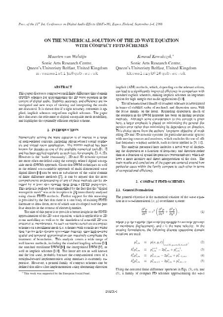
On the numerical solution of the 2D wave equation
On the numerical solution of the 2D wave equation
On the numerical solution of the 2D wave equation
You also want an ePaper? Increase the reach of your titles
YUMPU automatically turns print PDFs into web optimized ePapers that Google loves.
Proc. <strong>of</strong> <strong>the</strong> 11 th Int. Conference on Digital Audio Effects (DAFx-08), Espoo, Finland, September 1-4, 2008<br />
ON THE NUMERICAL SOLUTION OF THE <strong>2D</strong> WAVE EQUATION<br />
WITH COMPACT FDTD SCHEMES<br />
Maarten van Walstijn<br />
Sonic Arts Research Centre,<br />
Queen's Univeristy Belfast, United Kingdom<br />
m.vanwalstijn@qub.ac.uk<br />
Konrad Kowalczyk, ∗<br />
Sonic Arts Research Centre,<br />
Queen's Univeristy Belfast, United Kingdom<br />
kkowalczyk01@qub.ac.uk<br />
ABSTRACT<br />
This paper discusses compact-stencil nite difference time domain<br />
(FDTD) schemes for approximating <strong>the</strong> <strong>2D</strong> <strong>wave</strong> <strong>equation</strong> in <strong>the</strong><br />
context <strong>of</strong> digital audio. Stability, accuracy, and efciency are investigated<br />
and new ways <strong>of</strong> viewing and interpreting <strong>the</strong> results<br />
are discussed. It is shown that if a tight accuracy constraint is applied,<br />
implicit schemes outperform explicit schemes. The paper<br />
also discusses <strong>the</strong> relevance to digital <strong>wave</strong>guide mesh modelling,<br />
and highlights <strong>the</strong> optimally efcient explicit scheme.<br />
1. INTRODUCTION<br />
Numerically solving <strong>the</strong> <strong>wave</strong> <strong>equation</strong> is <strong>of</strong> interest in a range<br />
<strong>of</strong> audio-related contexts, including physics-based sound syn<strong>the</strong>sis<br />
and virtual room auralisation. The FDTD method has been<br />
known for decades as one <strong>of</strong> <strong>the</strong> available <strong>numerical</strong> tools [1, 2]<br />
and has been applied regularly as such (see, for example, [3, 4, 5]).<br />
However in <strong>the</strong> `audio community', <strong>2D</strong> and 3D acoustic systems<br />
are more <strong>of</strong>ten modelled using <strong>the</strong> strongly related digital <strong>wave</strong>guide<br />
mesh (DWM) approach. Given that DWM techniques as well<br />
as <strong>the</strong> related <strong>wave</strong>-variable approach <strong>of</strong> multi dimensional <strong>wave</strong><br />
digital lters [6] can be seen as sub-classes <strong>of</strong> <strong>the</strong> wider domain<br />
<strong>of</strong> nite difference methods [7], it can be argued that <strong>the</strong> most<br />
comprehensive understanding <strong>of</strong> any <strong>of</strong> <strong>the</strong>se methods can be obtained<br />
by at least also viewing <strong>the</strong>m from a FDTD perspective.<br />
This notion is perhaps best examplied by <strong>the</strong> fact that <strong>the</strong> “digital<br />
<strong>wave</strong>guide mesh” was at its inception in [8] immediately analysed<br />
using classic FDTD methods. Fur<strong>the</strong>r support for this reasoning<br />
is provided by <strong>the</strong> fact that <strong>the</strong>re is a vast body <strong>of</strong> existing FDTD<br />
literature to draw from, most <strong>of</strong> which was developed over <strong>the</strong> past<br />
four decades in <strong>the</strong> context <strong>of</strong> electrodynamics.<br />
The aim <strong>of</strong> this paper is to provide a better insight in <strong>the</strong> FDTD<br />
approximation <strong>of</strong> <strong>the</strong> <strong>2D</strong> <strong>wave</strong> <strong>equation</strong>, which is applicable to <strong>2D</strong><br />
room modelling as well as to <strong>the</strong> simulation <strong>of</strong> non-stiff <strong>2D</strong> resonators<br />
(i.e. membranes). As such we restrict ourselves to compact<br />
schemes on a rectilinear mesh (i.e. schemes with stencils not wider<br />
than 3 nodes in <strong>the</strong> discrete space-time domain), since higher-order<br />
spatial and temporal approximation can massively complicate <strong>the</strong><br />
treatment <strong>of</strong> boundaries. This analysis covers a wide range <strong>of</strong><br />
well known methods, including <strong>the</strong> standard leapfrog scheme [1],<br />
<strong>the</strong> standard rectilinear DWM [8], <strong>the</strong> interpolated DWM [9], as<br />
well as implicit schemes [10]. The latter are not as well known<br />
and far less used, probably because <strong>the</strong> computational costs <strong>of</strong> a<br />
straight-forward implementation using matrixes is extremely expensive.<br />
However, a general family <strong>of</strong> compact schemes can be<br />
dened that allows fast implementation using alternating direction<br />
∗<br />
This work was supported by <strong>the</strong> European Social Fund.<br />
implicit (ADI) methods, which, depending on <strong>the</strong> relevant critera,<br />
can lead to a signicantly improved efciency in comparison with<br />
standard explicit schemes, making implicit schemes an important<br />
option for high sample rate audio applications [10].<br />
The aforementioned family <strong>of</strong> compact schemes is investigated<br />
in terms <strong>of</strong> stability, order <strong>of</strong> accuracy, and dispersion error, with<br />
<strong>the</strong> focus mainly on <strong>the</strong> latter. Regarding dispersion, much <strong>of</strong><br />
<strong>the</strong> attention in <strong>the</strong> DWM literature has been on nding isotropic<br />
methods. Although some consideration to this concept is given<br />
here, a larger emphasis is placed on minimising <strong>the</strong> general dispersion<br />
error ra<strong>the</strong>r than minimising its dependence on direction.<br />
This choice stems from <strong>the</strong> authors' long-term objective <strong>of</strong> modelling<br />
<strong>2D</strong> and 3D acoustic systems (in particular acoustic spaces)<br />
with moving sources and receivers, which excludes <strong>the</strong> use <strong>of</strong> <strong>of</strong>fline<br />
frequency warping methods, such as those applied in [9, 11].<br />
The analysis presented here includes a novel way <strong>of</strong> displaying<br />
<strong>the</strong> dispersion as a function <strong>of</strong> frequency and direction ra<strong>the</strong>r<br />
than as a function <strong>of</strong> spatial frequencies (<strong>wave</strong>numbers), which allows<br />
a more intuitive and direct interpretation <strong>of</strong> <strong>the</strong> data. The<br />
main results and conclusions <strong>of</strong> <strong>the</strong> paper are centered around how<br />
particular cases within <strong>the</strong> family compare to each o<strong>the</strong>r in terms<br />
<strong>of</strong> computational efciency.<br />
2. COMPACT FDTD SCHEMES<br />
2.1. General Formulation<br />
The general objective is <strong>the</strong> <strong>numerical</strong> <strong>solution</strong> <strong>of</strong> <strong>the</strong> <strong>wave</strong> <strong>equation</strong><br />
in a two-dimensional (x, y) coordinate system:<br />
∂ 2 p<br />
∂t 2<br />
„ «<br />
∂ 2<br />
= p<br />
c2<br />
∂x + ∂2 p<br />
, (1)<br />
2 ∂y 2<br />
where p is <strong>the</strong> variable (that could for example be acoustic pressure<br />
or membrane displacement), and c is <strong>the</strong> <strong>wave</strong> velocity. In <strong>the</strong><br />
ensuing formulations, <strong>the</strong> following discrete space-time domain<br />
notations are used:<br />
p n ˛<br />
l,m ≡ p(x, y, t)<br />
δ 2 t p n l,m ≡ p n+1<br />
l,m<br />
˛x=lX,y=mX,t=nT<br />
, (2)<br />
− 2p n l,m + p n−1<br />
l,m , (3)<br />
δxp 2 n l,m ≡ p n l+1,m − 2p n l,m + p n l−1,m, (4)<br />
δyp 2 n l,m ≡ p n l,m+1 − 2p n l,m + p n l,m−1. (5)<br />
Using <strong>the</strong> centered nite difference operators in Eqs. (3), (4), and<br />
(5), a family <strong>of</strong> compact FD schemes approximating <strong>the</strong> <strong>wave</strong><br />
DAFX-1
Proc. <strong>of</strong> <strong>the</strong> 11 th Int. Conference on Digital Audio Effects (DAFx-08), Espoo, Finland, September 1-4, 2008<br />
<strong>equation</strong> can be formulated as follows [12]<br />
[1 + a(δ 2 x + δ 2 y) + a 2 δ 2 xδ 2 y]δ 2 t p n l,m = λ 2 [(δ 2 x + δ 2 y)<br />
+ bδ 2 xδ 2 y]p n l,m,<br />
where λ = cT/X is <strong>the</strong> Courant number, and a and b are free <strong>numerical</strong><br />
parameters. This formulation is consistent with <strong>the</strong> <strong>wave</strong><br />
<strong>equation</strong> for any real (a, b) (this is easily veried using <strong>equation</strong>s<br />
(42), (43), and (44)), and <strong>the</strong> resulting scheme is implicit except for<br />
a = 0. While a more generalised family <strong>of</strong> compact schemes is<br />
possible [5], it is useful to restrict <strong>the</strong> analysis <strong>of</strong> possible implicit<br />
schemes to those that can be factorised into two one-dimensional<br />
implicit <strong>equation</strong>s. In that case, an alternating direction implicit<br />
(ADI) formulation exists, which allows a fast implementation using<br />
<strong>the</strong> Thomas algorithm for matrix inversion [1, 2]. In <strong>the</strong> light<br />
<strong>of</strong> that constraint, <strong>the</strong> formulation in (6) is particularly useful since<br />
it allows splitting into <strong>the</strong> following ADI form, which is more ef-<br />
cient than alternative splitting formulae [12]<br />
(1 + aδ 2 x)p n+1∗<br />
l,m<br />
(1 + aδ 2 y)δ 2 t p n l,m = p n+1∗<br />
l,m<br />
where p n l,m is <strong>the</strong> update variable and p n+1∗<br />
l,m<br />
value.<br />
(6)<br />
= λ2<br />
a [−1 + (a − b)δ2 y]p n l,m, (7)<br />
+ λ2<br />
a (1 + bδ2 y)p n l,m, (8)<br />
is an intermediate<br />
2.2. Single-Frequency Plane-Wave Solutions<br />
Many standard methods for analysis <strong>of</strong> FDTD schemes are based<br />
on examining single-frequency plane-<strong>wave</strong> <strong>solution</strong>s. Consider<br />
such a <strong>wave</strong> travelling at position x ′ along an axis that cuts <strong>the</strong><br />
Cartesian x-axis at an angle θ. In <strong>the</strong> continuous space-time domain,<br />
<strong>solution</strong>s <strong>of</strong> this kind can be written<br />
p(x ′ , t) = p 0 e st e −jkx′ , (9)<br />
where p 0 is a real-valued amplitude value, s = σ + jω denotes<br />
complex frequency, and k is <strong>the</strong> <strong>wave</strong>number. Using <strong>the</strong> coordinate<br />
rotation x ′ = x cos(θ) + y sin(θ), this becomes<br />
p(x, y, t) = p 0 e st e −jkxx e −jkyy , (10)<br />
where k x = k cos θ and k y = k sin θ. In <strong>the</strong> discrete space-time<br />
domain, <strong>the</strong> single-frequency plane-<strong>wave</strong> <strong>solution</strong> is:<br />
p n l,m = p 0 e snT e −jˆk x lX e −jˆk y mX , (11)<br />
where ˆk x and ˆk y denote <strong>the</strong> effective <strong>numerical</strong> <strong>wave</strong>numbers,<br />
which differ from <strong>the</strong> continuous-domain <strong>wave</strong>numbers and are<br />
related to a <strong>wave</strong>number ˆk associated with <strong>the</strong> propagation direction<br />
along <strong>the</strong> x ′ -axis by<br />
ˆk 2 = ˆk 2 x + ˆk 2 x. (12)<br />
For <strong>solution</strong>s <strong>of</strong> this form, <strong>the</strong> approximation in (3) can be written<br />
δ 2 t p n l,m = `z − 2 + z −1´ p n l,m,<br />
= −4 sin 2 (ωT/2) p n l,m, (13)<br />
where z = e sT , which represents <strong>the</strong> classic relationship between<br />
<strong>the</strong> s- and <strong>the</strong> z-domain found in DSP literature. Hence by <strong>the</strong><br />
z-transform shift <strong>the</strong>orem, we have<br />
p n+1<br />
l,m = z p n l,m, (14)<br />
which is easily veried by substituting both sides <strong>of</strong> Eq. (14) with<br />
<strong>the</strong> form <strong>of</strong> Eq. (11). Similarly, under <strong>the</strong> assumption <strong>of</strong> singlefrequency<br />
plane-<strong>wave</strong> <strong>solution</strong>s <strong>the</strong> spatial approximations in (4)<br />
and (5) can be written<br />
δxp 2 n l,m = −4 sin 2 (ˆk xX/2) p n l,m, (15)<br />
δyp 2 n l,m = −4 sin 2 (ˆk y X/2) p n l,m. (16)<br />
2.3. Von Neuman Stability Analysis<br />
Classic von Neumann stability analysis investigates an FDTD scheme<br />
for <strong>solution</strong>s <strong>of</strong> <strong>the</strong> form <strong>of</strong> Eq. (11), and seeks to establish a bound<br />
on λ such that no growing <strong>solution</strong>s exist [1, 2]. From (14) it is<br />
clear that any scheme is unstable for |z| > 1, hence <strong>the</strong> necessary<br />
stability condition can be expressed as |z| ≤ 1. By substituting<br />
(13), (15), and (16) into (6), <strong>the</strong> following <strong>equation</strong> in z can be<br />
obtained:<br />
z + 2B(s x , s y ) + z −1 = 0, (17)<br />
where following [5] we introduce <strong>the</strong> new variables<br />
s x = sin 2 (ˆk xX/2), (18)<br />
s y = sin 2 (ˆk y X/2), (19)<br />
and where<br />
B(s x, s y) = 2λ 2 F (s x, s y) − 1, (20)<br />
with<br />
F (s x , s y ) =<br />
s x + s y − 4bs xs y<br />
1 − 4a(s x + s y ) + 16a 2 s x s y<br />
. (21)<br />
In FDTD literature, Eq. (17) is known as <strong>the</strong> amplication <strong>equation</strong><br />
or <strong>the</strong> amplication polynomial. The moduli <strong>of</strong> its two <strong>solution</strong>s<br />
have to be smaller than or equal to unity for any combination<br />
(s x , s y ) and thus any combination (ˆk x , ˆk y ). Since s x and<br />
s y are periodic with π, it is sufcient to consider only real-valued<br />
<strong>wave</strong>numbers in <strong>the</strong> range −π/X ≤ ˆk x , ˆk y ≤ π/X. We note<br />
that ˆk x and ˆk y can also become complex-valued [13], but in that<br />
case only <strong>the</strong> real part has to be taken into account with regard to<br />
stability analysis. From (17), it can be shown that |z| ≤ 1 when<br />
B 2 (s x, s y) ≤ 1 (22)<br />
which yields <strong>the</strong> bound on λ:<br />
λ 2 ≤<br />
1<br />
F max (s x , s y )<br />
(23)<br />
For any (a, b) <strong>the</strong> function F (s x , s y ) reaches its maximum at one<br />
<strong>of</strong> its extrema, where s x, s y ∈ [0, 1], thus<br />
F max = max<br />
„ «<br />
1<br />
1 − 4a , 2 − 4b<br />
1 − 8a + 16a 2<br />
1 − 8a + 16a2<br />
2 − 4b<br />
(24)<br />
Therefore <strong>the</strong> necessary stability condition for <strong>the</strong> scheme in (6) is<br />
«<br />
λ 2 ≤ min<br />
„1 − 4a, . (25)<br />
Since λ 2 must be positive, it follows from (25) that we have <strong>the</strong><br />
auxiliary constraints:<br />
a ≤ 1 4 , b ≤ 1 2 . (26)<br />
DAFX-2
Proc. <strong>of</strong> <strong>the</strong> 11 th Int. Conference on Digital Audio Effects (DAFx-08), Espoo, Finland, September 1-4, 2008<br />
2.4. Numerical Dispersion<br />
If we re-arrange (17) to<br />
z − 2 + z −1 = −4λ 2 F (s x , s y ), (27)<br />
and, using (13), substitute z − 2 + z −1 = −4 sin(ωT/2), <strong>the</strong>n <strong>the</strong><br />
dispersion relation results:<br />
sin 2 (ωT/2) = λ 2 F (s x , s y ). (28)<br />
The frequency for (s x, s y) is <strong>the</strong>refore<br />
ω = 2 “λ<br />
T arcsin p ”<br />
F (s x , s y ) . (29)<br />
The relative phase velocity, dened as <strong>the</strong> ratio <strong>of</strong> <strong>the</strong> effective<br />
<strong>numerical</strong> <strong>wave</strong> speed ĉ = ω/ˆk over <strong>the</strong> real <strong>wave</strong> speed c, is a<br />
useful measure <strong>of</strong> <strong>numerical</strong> dispersion. Using (29) and (12), one<br />
obtains<br />
v(ˆk x , ˆk y ) = ωˆk c<br />
=<br />
“<br />
2 arcsin<br />
λ<br />
λ p ”<br />
F (s x, s y)<br />
q(ˆk x X) 2 + (ˆk y X) 2 . (30)<br />
2.5. Axial Phase Velocity<br />
Consider now <strong>wave</strong> propagation in one <strong>of</strong> <strong>the</strong> four axial directions,<br />
where ˆk a denotes <strong>the</strong> <strong>wave</strong>number. Then we have ei<strong>the</strong>r nˆk2 x =<br />
ˆk a, 2 ˆk<br />
o<br />
y 2 = 0 or<br />
nˆk2 x = 0, ˆk y 2 = ˆk<br />
o<br />
a<br />
2 , which in both cases allows<br />
writing <strong>the</strong> variable F as a function <strong>of</strong> <strong>the</strong> axial <strong>wave</strong>number:<br />
F (ˆk a) =<br />
sin 2 (ˆk a X/2)<br />
1 − 4a sin 2 (ˆk a X/2) . (31)<br />
Then from Eq. (28), <strong>the</strong> axial <strong>wave</strong>number can be written as a<br />
unique function <strong>of</strong> frequency:<br />
ˆk a (ω) = 2 X arcsin s<br />
sin 2 (ωT/2)<br />
λ 2 + 4a sin 2 (ωT/2) , (32)<br />
and nally <strong>the</strong> relative phase velocity in axial directions can now<br />
also be written as a function <strong>of</strong> frequency<br />
v a (ω) =<br />
ω<br />
ˆk a(ω) c =<br />
(ωT/2)<br />
q<br />
λ arcsin<br />
sin 2 (ωT /2)<br />
λ 2 +4a sin 2 (ωT /2)<br />
. (33)<br />
2.6. Diagonal Phase Velocity<br />
In diagonal directions, we have ˆk 2 x = ˆk 2 y = ˆk 2 d/2 (subscript d denoting<br />
diagonal directions), which allows writing F as a function<br />
<strong>of</strong> <strong>the</strong> diagonal <strong>wave</strong>number:<br />
F (ˆk d ) =<br />
2G(ˆk d ) − 4bG 2 (ˆk d )<br />
1 − 8aG(ˆk d ) + 16a 2 G 2 (ˆk d ) , (34)<br />
where G(ˆk d ) = sin 2 ( √ 2ˆk d X/4). Forcing <strong>the</strong> dispersion relation<br />
in (28) and writing G as a function <strong>of</strong> frequency yields<br />
G(ω) = 4ast − λ2 − p (8a − 4b)λ 2 s t + λ 4 )<br />
16a 2 s t + 4bλ 2 , (35)<br />
where s t = sin 2 (ωT/2). Using <strong>the</strong> denition <strong>of</strong> G, we may <strong>the</strong>n<br />
write <strong>the</strong> diagonal <strong>wave</strong>number as a function <strong>of</strong> frequency:<br />
ˆk d (ω) =<br />
4<br />
√<br />
2X arcsin<br />
p<br />
G(ω)<br />
. (36)<br />
Finally, <strong>the</strong> relative <strong>wave</strong> velocity in diagonal directions as a function<br />
<strong>of</strong> frequency becomes<br />
q<br />
1<br />
ω<br />
(ωT/2)<br />
v d (ω) =<br />
ˆk d (ω) c =<br />
2<br />
λ arcsin p G(ω) . (37)<br />
2.7. Cut-Off Frequencies<br />
The function f(x) = arcsin(x) becomes complex-valued when<br />
x > 1. Hence from (32), <strong>the</strong> axial <strong>wave</strong>number becomes complexvalued<br />
if<br />
sin 2 (ωT/2)<br />
λ 2 + 4a sin 2 > 1, (38)<br />
(ωT/2)<br />
which can be simplied to<br />
„ «<br />
λ<br />
ωT > 2 arcsin √ 1 − 4a<br />
. (39)<br />
For frequencies above this `cut-<strong>of</strong>f' frequency, <strong>wave</strong>s are evanescent,<br />
and resonances are not sustained [13]. Such a cut-<strong>of</strong>f frequency<br />
in fact exists for all propagation directions, and can be<br />
found by considering for which frequencies <strong>the</strong> dispersion relation<br />
in (28) can be satised only for complex-valued <strong>wave</strong>numbers,<br />
which yields:<br />
ωT > 2 arcsin<br />
“<br />
λ p ”<br />
F mr(θ . (40)<br />
where F mr (θ) is <strong>the</strong> maximum value <strong>of</strong> F (s x , s y ) for a pair <strong>of</strong><br />
real-valued <strong>wave</strong>numbers for which <strong>the</strong> angle <strong>of</strong> propagation is θ:<br />
F mr(θ) =<br />
j<br />
F (1, sin 2 (π/2 tan θ), | tan θ| ≤ 1<br />
F (sin 2 (π/2 tan θ), 1), | tan θ| > 1<br />
(41)<br />
2.8. Order <strong>of</strong> Acuracy<br />
Truncating to fourth order <strong>the</strong> Taylor expansions about <strong>the</strong> point<br />
(x, y, t) <strong>of</strong> <strong>the</strong> difference operators in Eqs. (3), (4), and (5) yields:<br />
δt 2 = T 2 ∂ 2<br />
∂t + T 4<br />
2 12<br />
δ 2 x = X 2 ∂ 2<br />
δ 2 y = X 2 ∂ 2<br />
∂x 2 + X4<br />
12<br />
∂y 2 + X4<br />
12<br />
∂ 4<br />
∂t 4 + O(T 4 ), (42)<br />
∂ 4<br />
∂x + 4 O(X4 ), (43)<br />
∂ 4<br />
∂y + 4 O(X4 ). (44)<br />
Substitution <strong>of</strong> <strong>the</strong> above <strong>equation</strong>s into <strong>the</strong> general scheme <strong>of</strong> (6)<br />
and applying <strong>the</strong> required successive substitutions <strong>of</strong> derivatives<br />
according to <strong>the</strong> modied <strong>equation</strong> method [14, 5] <strong>the</strong>n allows expressing<br />
<strong>the</strong> overall <strong>numerical</strong> error or modied <strong>equation</strong> error as<br />
" „<br />
E(p, a, b, λ, X) = −c 2 a + λ2 − 1<br />
12<br />
„<br />
+ b − 1 6<br />
« ∂ 4 p<br />
∂x 4<br />
« #<br />
∂ 4 p<br />
X 2 + O(X 4 ).<br />
∂x 2 ∂y 2<br />
(45)<br />
DAFX-3
Proc. <strong>of</strong> <strong>the</strong> 11 th Int. Conference on Digital Audio Effects (DAFx-08), Espoo, Finland, September 1-4, 2008<br />
Stanfard Leap Frog (SLF) Rotated Leap Frog (RLF) Interpolated (INT) Implicit<br />
(n+1)<br />
(n)<br />
(l-1,m-1) (l,m-1)<br />
(l+1,m-1)<br />
(l+1,m+1 )<br />
(l+1,m)<br />
(l-1,m-1) (l,m-1) (l+1,m-1)<br />
(l+1,m)<br />
(l+1,m+1 )<br />
(l-1,m-1) (l,m-1) (l+1,m-1)<br />
(l+1,m)<br />
(l+1,m+1 )<br />
(l-1,m-1) (l,m-1) (l+1,m-1)<br />
(l+1,m)<br />
(l+1,m+1 )<br />
(n-1)<br />
Figure 1: Compact FDTD Stencils. For each type <strong>of</strong> stencil, <strong>the</strong> middle node at time (n + 1) is updated using <strong>the</strong> remaining black-coloured<br />
nodes.<br />
3. ANALYSIS OF SPECIAL CASES<br />
Table 1 lists seven special cases <strong>of</strong> compact schemes. The standard<br />
leapfrog (SLF) scheme is ma<strong>the</strong>matically equivalent to <strong>the</strong> rectilinear<br />
digital <strong>wave</strong>guide mesh [8], and has exactly <strong>the</strong> same dispersion<br />
relation as Yee's classic FDTD scheme [15, 2]. As explained<br />
in [5], <strong>the</strong> rotated leap fog (RLF) scheme can be interpreted as applying<br />
standard centered nite operators along <strong>the</strong> diagonals ra<strong>the</strong>r<br />
than <strong>the</strong> horizontal and vertical axes. <strong>On</strong>e could say that <strong>the</strong> RLF<br />
stencil is 45 o rotated in comparison to <strong>the</strong> SLF scheme; both use<br />
a “6-point stencil” in <strong>the</strong> space-time grid to update <strong>the</strong> new value<br />
at time (n + 1) (see Fig. 1). Linear combinations <strong>of</strong> <strong>the</strong> SLF and<br />
<strong>the</strong> RLF also exist, which result in a 10-point update stencil (see<br />
Fig. 1). Such schemes, for which a = 0 and 0 < b < 1 2, have<br />
been referred to as `interpolated schemes' [5]. We have listed two<br />
special cases <strong>of</strong> interpolated schemes in Table 1. As a reference to<br />
o<strong>the</strong>r studies, it is useful to point out that <strong>the</strong> interpolated scheme<br />
with b = 1 and λ = p 1<br />
6 2<br />
is nearly equivalent to <strong>the</strong> interpolated<br />
digital <strong>wave</strong>guide mesh [10], <strong>the</strong> latter having b = 0.1879.<br />
Table 1: Special cases <strong>of</strong> compact FDTD schemes.<br />
scheme a b stability bound<br />
SLF 0 0 λ ≤ p 1<br />
2<br />
RLF 0<br />
1<br />
2<br />
λ ≤ 1<br />
INT(1/4) 0<br />
1<br />
4<br />
λ ≤ 1<br />
INT(1/6) 0<br />
1<br />
6<br />
λ ≤ p 3<br />
4<br />
MFI<br />
1<br />
4 − 1<br />
2 √ 3<br />
FOA<br />
1−λ 2<br />
12<br />
1<br />
6<br />
λ ≤ 1<br />
1<br />
λ ≤ √ 3 − 1<br />
6<br />
OPT 0.0492 0.228 λ ≤ 0.77<br />
The remaining special cases in Table 1 are implicit schemes,<br />
which use a 26-point update stencil (see Fig. 1). The maximally<br />
at isotropic (MFI) scheme is <strong>the</strong> scheme for which <strong>the</strong> difference<br />
between axial and diagonal relative phase velocity is maximally<br />
at. Such a scheme is particularly useful when <strong>the</strong> aim is to apply<br />
(<strong>of</strong>f-line) pre- and post-warping techniques in order to remove as<br />
much as possible any direction-independent <strong>numerical</strong> dispersion,<br />
such as those presented in [9].<br />
The implicit scheme with a = 1−λ2 and b = 1 12 6, originally<br />
identied in [16], denes a subgroup <strong>of</strong> schemes within <strong>the</strong> familiy<br />
<strong>of</strong> Eq. (6) <strong>of</strong> fourth-order accuracy (FOA), as can be seen directly<br />
from Eq. (45).<br />
The OPT scheme is an optimisation example, that is computationally<br />
most efcient under <strong>the</strong> criterion that <strong>the</strong> relative phase<br />
velocity error should not exceed 1% within any specied bandwidth<br />
(see Sec. 3.2).<br />
3.1. Relative Phase Velocity<br />
In Fig. 2, <strong>the</strong> relative phase velocity, as calculated with (30), is<br />
plotted as a function <strong>of</strong> <strong>the</strong> <strong>wave</strong>numbers. What can be immediately<br />
observed from <strong>the</strong>se plots is how `isotropic' a particular<br />
scheme is. For example, <strong>the</strong> INT(1/6) scheme (results plotted for<br />
both λ 2 = 0.75, which is <strong>the</strong> stability bound, and λ 2 = 0.5,<br />
which coincides with <strong>the</strong> interpolated digital <strong>wave</strong>guide mesh) and<br />
<strong>the</strong> MFI scheme are far more `round' than <strong>the</strong> o<strong>the</strong>r special cases.<br />
Note that <strong>the</strong> MFI scheme is <strong>the</strong> most isotropic <strong>of</strong> <strong>the</strong> three.<br />
What is difcult - if not impossible - to determine from <strong>the</strong>se<br />
plots is <strong>the</strong> <strong>numerical</strong> dispersion at a certain frequency. In some<br />
studies [11, 17], a circle is drawn on plots <strong>of</strong> this type with <strong>the</strong> intention<br />
<strong>of</strong> indicating <strong>the</strong> “highest normalised temporal frequency”.<br />
Unfortunately this does not work, since <strong>the</strong> <strong>wave</strong>numbers (spatial<br />
frequencies) are not proportional to <strong>the</strong> temporal frequencies (this<br />
follows straight from <strong>the</strong> dispersion relation).<br />
It is however possible to convert a set <strong>of</strong> <strong>wave</strong>numbers (ˆk x, ˆk y)<br />
to frequency ω (using Eq. (29)) and angle <strong>of</strong> propagation θ. This<br />
way `polar plots' <strong>of</strong> <strong>the</strong> relative phase velocity can be generated,<br />
where <strong>the</strong> polar radius corresponds to (normalised) frequency and<br />
<strong>the</strong> polar angle indicates <strong>the</strong> direction (see Fig. 3). Now we may<br />
draw circles on <strong>the</strong> plot in order to indicate particular frequencies.<br />
These plots also immediately reveal <strong>the</strong> cut-<strong>of</strong>f frequency<br />
for any direction (beyond which <strong>wave</strong>s in <strong>the</strong> discrete system are<br />
evanescent and dispersion is <strong>of</strong> highly reduced relevance). As can<br />
be seen, only <strong>the</strong> INT(1/4) scheme lls <strong>the</strong> complete bandwidth<br />
up to Nyquist for all directions, while <strong>the</strong> SLF, <strong>the</strong> RLF, and <strong>the</strong><br />
INT(1/6) with λ 2 = 0.5 have <strong>the</strong> most `severe' cut-<strong>of</strong>f frequencies<br />
İt can also be observed from Fig. 3 that <strong>the</strong> FOA and <strong>the</strong> OPT<br />
scheme have <strong>the</strong> largest bandwidth in which <strong>the</strong> <strong>numerical</strong> dispersion<br />
remains relatively small. Amongst <strong>the</strong> explicit schemes, <strong>the</strong><br />
INT(1/6) (with λ 2 = 0.75) and <strong>the</strong> INT(1/4) scheme perform relatively<br />
well in that regard.<br />
A general observation that can be made is that <strong>the</strong> highest <strong>numerical</strong><br />
dispersion consistently occurs in ei<strong>the</strong>r <strong>the</strong> axial or <strong>the</strong> diagonal<br />
direction. Hence perhaps <strong>the</strong> most useful and informative<br />
is to plot <strong>the</strong> relative phase velocity only for <strong>the</strong>se directions, as<br />
depicted in Fig. 4. This allows better to observe <strong>the</strong> exact value <strong>of</strong><br />
DAFX-4
Proc. <strong>of</strong> <strong>the</strong> 11 th Int. Conference on Digital Audio Effects (DAFx-08), Espoo, Finland, September 1-4, 2008<br />
π<br />
SLF<br />
π<br />
RLF<br />
π<br />
INT(1/4)<br />
k y<br />
X<br />
0<br />
k y<br />
X<br />
0<br />
k y<br />
X<br />
0<br />
−π<br />
−π 0 π<br />
−π<br />
−π 0 π<br />
−π<br />
−π 0 π<br />
k x<br />
X<br />
k x<br />
X<br />
k x<br />
X<br />
π<br />
INT(1/6) [λ 2 = 0.75]<br />
π<br />
INT(1/6) [λ 2 = 0.5]<br />
π<br />
MFI<br />
k y<br />
X<br />
0<br />
k y<br />
X<br />
0<br />
k y<br />
X<br />
0<br />
−π<br />
−π 0 π<br />
−π<br />
−π 0 π<br />
−π<br />
−π 0 π<br />
k x<br />
X<br />
k x<br />
X<br />
k x<br />
X<br />
π<br />
FOA<br />
π<br />
OPT<br />
color bar<br />
k y<br />
X<br />
0<br />
k y<br />
X<br />
0<br />
0.7 0.8 0.9 1<br />
relative phase velocity<br />
−π<br />
−π 0 π<br />
−π<br />
−π 0 π<br />
k x<br />
X<br />
k x<br />
X<br />
Figure 2: Relative phase velocity as a function <strong>of</strong> x- and y-direction <strong>wave</strong>numbers. The darkness in <strong>the</strong> plots indicates <strong>the</strong> relative phase<br />
velocity error, where white indicates a zero error, and any error larger <strong>the</strong>n or equal to 0.3 is represented with black.<br />
<strong>the</strong> relative phase velocity, and for example reveals more clearly<br />
that v a exceeds unity for <strong>the</strong> OPT scheme.<br />
3.2. Computational Efciency<br />
While <strong>the</strong> relative phase velocity is a useful indicator <strong>of</strong> <strong>the</strong> characteristics<br />
<strong>of</strong> a scheme, <strong>the</strong> plots in Figs. 2, 3, and 4 do not allow a<br />
direct interpretation <strong>of</strong> how efcient <strong>the</strong>y are in comparison. This<br />
is mainly because <strong>the</strong>y use different Courant numbers. While some<br />
insight can be gained from comparing schemes for equal Courant<br />
numbers (see, for example, [5]), it seems more informative to restrict<br />
any comparisons to schemes at <strong>the</strong>ir highest possible value<br />
<strong>of</strong> <strong>the</strong> Courant number (provided that λ ≤ 1), since that is when<br />
<strong>the</strong> <strong>numerical</strong> dispersion is generally <strong>the</strong> lowest. In order to investigate<br />
<strong>the</strong> dependence <strong>of</strong> computational efciency on <strong>the</strong> free<br />
parameters (a, b) (with λ chosen at <strong>the</strong> stability bound), <strong>the</strong> effect<br />
<strong>of</strong> different λ values has to be taken into account.<br />
In an audio context, one <strong>of</strong>ten requires precise results over a<br />
specied bandwidth. For example, in room acoustics applications<br />
<strong>the</strong> dispersion error should ideally be kept low up to <strong>the</strong> highest<br />
available frequency, as o<strong>the</strong>rwise compact <strong>wave</strong>fronts are smeared<br />
out over time, which is likely to affect <strong>the</strong> capability <strong>of</strong> <strong>the</strong> listener<br />
to localise sources. Thus a suitable metric for computational costs<br />
dened as <strong>the</strong> amount <strong>of</strong> computation required in order to obtain<br />
a certain accuracy over a certain bandwidth 1 . For <strong>the</strong> purpose <strong>of</strong><br />
1For membrane syn<strong>the</strong>sis, it might make more sense to use a different<br />
metric that allows <strong>the</strong> error to increase with frequency, since dispersion<br />
at high frequencies are not that relevant in that scenario. However, <strong>the</strong><br />
conclusions regarding explicit schemes are actually generally applicable,<br />
DAFX-5
Proc. <strong>of</strong> <strong>the</strong> 11 th Int. Conference on Digital Audio Effects (DAFx-08), Espoo, Finland, September 1-4, 2008<br />
SLF 90 o<br />
135 o<br />
45 o<br />
−180 o<br />
0 o<br />
−135 o −45 o<br />
−90 o<br />
−180 o<br />
RLF 90 o<br />
135 o<br />
45 o<br />
−135 o −90 o −45 o 0 o<br />
INT(1/4)<br />
135 o<br />
−180 o<br />
90 o<br />
45 o<br />
−135 o −90 o −45 o 0 o<br />
INT(1/6) [λ 2 = 0.75]<br />
90 o<br />
INT(1/6) [λ 2 = 0.5]<br />
90 o<br />
MFI<br />
90 o<br />
135 o<br />
45 o<br />
135 o<br />
45 o<br />
135 o<br />
45 o<br />
−180 o<br />
−135 o −90 o −45 o 0 o<br />
−180 o<br />
−135 o −90 o −45 o 0 o<br />
−180 o<br />
−135 o −90 o −45 o 0 o<br />
FOA<br />
90 o<br />
OPT<br />
90 o<br />
135 o<br />
45 o<br />
135 o<br />
45 o<br />
color bar<br />
−180 o<br />
−135 o −90 o −45 o 0 o<br />
−180 o<br />
−135 o −90 o −45 o 0 o<br />
0.7 0.8 0.9 1<br />
relative phase velocity<br />
Figure 3: Relative phase velocity as a function <strong>of</strong> frequency (polar plot radius) and propagation angle (polar plot angle). In each plot,<br />
starting from <strong>the</strong> most inner circle, <strong>the</strong> dotted-line circles indicate f = ( 1 8 , 1 4 , 3 8 , 1 2 )fs.<br />
comparing <strong>the</strong> schemes in that sense, let's specify this as<br />
<strong>the</strong> computational density required such that <strong>the</strong> deviation<br />
<strong>of</strong> <strong>the</strong> relative phase velocity from its ideal<br />
unity value is not larger than a critical error e c up<br />
to a critical frequency ω c.<br />
As a rst indication, we may dene <strong>the</strong> computational density simply<br />
as <strong>the</strong> number <strong>of</strong> nodal updates per square meter per second.<br />
This enables direct comparison between schemes that use exactly<br />
<strong>the</strong> same nodal update computations, such as all implicit schemes.<br />
Using this denition <strong>of</strong> computational density, we can dene <strong>the</strong><br />
and although we have not explictly addressed alternative metrics, some<br />
tentative conclusions regarding implicit schemes could also be made for<br />
<strong>the</strong> separate case <strong>of</strong> membrane syn<strong>the</strong>sis on basis <strong>of</strong> <strong>the</strong> analysis presented.<br />
following metric <strong>of</strong> relative efciency:<br />
ε(a, b, e c ) =<br />
ρnu(0, 0, ec, ωc)<br />
ρ nu (a, b, e c , ω c ) , (46)<br />
where ρ nu(a, b, e c, ω c) denotes <strong>the</strong> computational density for scheme<br />
(a, b) that meets <strong>the</strong> criterion (e c, ω c) and ρ nu(0, 0, e c, ω c) is <strong>the</strong><br />
reference (SLF) scheme that we normalise by. Note that while ρ nu<br />
depends on <strong>the</strong> critical frequency, ε does not.<br />
The value <strong>of</strong> ρ nu is calculated by rst determining <strong>the</strong> sampling<br />
frequency required to meet <strong>the</strong> accuracy criterion, for which<br />
Eqs. (33) and (37) can be used. This involves rst determining<br />
<strong>the</strong> (normalised) frequencies ω a T and ω d T at which |1 − v a | and<br />
|1 − v d | are equal to e c . Because (33) and (37) are not directly<br />
invertable, this has to be done using optimisation methods. <strong>On</strong>ce<br />
<strong>the</strong>se critical frequencies have been found, <strong>the</strong> required sample rate<br />
DAFX-6
Proc. <strong>of</strong> <strong>the</strong> 11 th Int. Conference on Digital Audio Effects (DAFx-08), Espoo, Finland, September 1-4, 2008<br />
relative phase velocity<br />
relative phase velocity<br />
1.05<br />
1<br />
0.95<br />
0.9<br />
0.85<br />
0.8<br />
0.75<br />
SLF<br />
RLF<br />
INT(1/4)<br />
INT(1/6)<br />
MFI<br />
FOA<br />
OPT<br />
AXIAL DIRECTIONS<br />
0.7<br />
0 0.1 0.2 0.3 0.4 0.5<br />
normalised frequency<br />
1.05<br />
1<br />
0.95<br />
0.9<br />
0.85<br />
0.8<br />
0.75<br />
SLF<br />
RLF<br />
INT(1/4)<br />
INT(1/6)<br />
MFI<br />
FOA<br />
OPT<br />
DIAGONAL DIRECTIONS<br />
0.7<br />
0 0.1 0.2 0.3 0.4 0.5<br />
normalised frequency<br />
Figure 4: Relative phase veloctiy for axial directions (top), and<br />
diagonal directions (bottom).<br />
ω<br />
is calculated as f s =<br />
c<br />
min(ω a T,ω d T ). The required spatial step X<br />
is <strong>the</strong>n obtained directly from λ = (cT )/X. The required nodal<br />
density is thus ρ n = X −2 nodes per m 2 , and <strong>the</strong> required computational<br />
density (as in <strong>the</strong> number <strong>of</strong> nodal updates per m 2 per<br />
second) is ρ nu =<br />
Calculations <strong>of</strong> ε(a, b, e c ) have been performed for a large set<br />
(a, b) and a range <strong>of</strong> e c values. An example result (e c = 1%) is<br />
plotted in Fig. 5.<br />
fs .<br />
(X) 2<br />
Table 2: Relative Efciency ε(e c ).<br />
scheme ε(10%) ε(1%) ε(0.1%) ε(0.01%)<br />
SLF 1.00 1.00 1.00 1.00<br />
RLF 0.50 0.50 0.50 0.50<br />
INT(1/4) 4.00 4.00 4.00 4.00<br />
INT(1/6) 2.16 3.23 3.44 3.46<br />
MFI 2.08 1.65 1.59 1.58<br />
FOA 2.42 12.3 71.4 408<br />
OPT 3.50 41.9 5.10 4.91<br />
Table 2 shows <strong>the</strong> relative efciency <strong>of</strong> <strong>the</strong> special cases at<br />
<strong>the</strong>ir top Courant number for e c = 10%, 1%, 0.1%, and 0.01%.<br />
Note that one cannot directly compare values <strong>of</strong> different columns.<br />
Direct comparison is also not possible between schemes that use<br />
different amounts <strong>of</strong> nodes in <strong>the</strong>ir stencil, since this is not taken<br />
into account in <strong>the</strong> calculations. However, some important conclusions<br />
regarding such comparisons can still be drawn without<br />
getting into <strong>the</strong> messy business <strong>of</strong> counting FLOPS:<br />
• A nodal update with an interpolated scheme requires only<br />
a<br />
0.25<br />
0.2<br />
0.15<br />
0.1<br />
0.05<br />
0<br />
−0.05<br />
−0.1<br />
−0.15<br />
−0.2<br />
−0.25<br />
0 0.1 0.2 0.3 0.4 0.5<br />
b<br />
Figure 5: Relative efciency (plotted as log 2 [ε(a, b, e c )]) for e c =<br />
0.01. The optimal scheme lies in <strong>the</strong> white area. For any combination<br />
<strong>of</strong> <strong>the</strong> free parameters (a, b), <strong>the</strong> Courant number was chosen<br />
at <strong>the</strong> stability bound.<br />
a fraction <strong>of</strong> additional arithmetics in comparison with <strong>the</strong><br />
SLF or <strong>the</strong> RLF scheme [10]. Hence it follows that <strong>the</strong><br />
INT(1/4) is nearly 4 times more efcient than <strong>the</strong> SLF for<br />
any possible value <strong>of</strong> e c .<br />
• Inspection <strong>of</strong> results along <strong>the</strong> line a = 0 reveals <strong>the</strong><br />
remarkable notion that amongst <strong>the</strong> explicit schemes, <strong>the</strong><br />
INT(1/4) is always <strong>the</strong> optimally efcient scheme, regardless<br />
<strong>of</strong> <strong>the</strong> choice <strong>of</strong> e c .<br />
• Regarding implicit schemes (which all require exactly <strong>the</strong><br />
same computational costs per nodal update for a given ADI<br />
implementation), <strong>the</strong> FOA scheme is <strong>the</strong> most efcient option,<br />
except when <strong>the</strong> cricital error is high, in which case a<br />
signicant better scheme can be found via optimisation.<br />
• As for comparing explicit schemes with implicit schemes,<br />
<strong>the</strong> computational costs <strong>of</strong> <strong>the</strong> ADI method per nodal update<br />
is roughly twice as much as that <strong>of</strong> explicit schemes<br />
[10]. Therefore it can be concluded that an implicit scheme<br />
that is more efcient than any explicit scheme can almost<br />
always be found, except if <strong>the</strong> critical error is chosen very<br />
high (e c > 2%).<br />
Additional insight can be gained by marking <strong>the</strong> positions <strong>of</strong><br />
<strong>the</strong> various schemes on a map <strong>of</strong> <strong>the</strong> (a, b) domain (see Fig. 6).<br />
The solid line indicates <strong>the</strong> positions <strong>of</strong> optimised schemes when<br />
varying <strong>the</strong> critical error from e c = 10% to e c = 0.01%. The FOA<br />
scheme can be seen as <strong>the</strong> optimal scheme for e c → 0, and has <strong>the</strong><br />
`maximally at' phase velocity error. Ano<strong>the</strong>r interesting point is<br />
that <strong>the</strong> FOA scheme with λ at its top value uses a = − 1 + 1<br />
4 2 √ , 3<br />
thus is <strong>the</strong> `mirror-image' <strong>of</strong> <strong>the</strong> MFI scheme in <strong>the</strong> (a, b) domain.<br />
4. CONCLUSIONS<br />
Compact FDTD schemes describe a useful group <strong>of</strong> nite difference<br />
methods and related techniques for simulation <strong>of</strong> acoustic<br />
systems governed by <strong>the</strong> <strong>wave</strong> <strong>equation</strong>. While considerable<br />
5<br />
0<br />
−5<br />
−10<br />
−15<br />
DAFX-7
Proc. <strong>of</strong> <strong>the</strong> 11 th Int. Conference on Digital Audio Effects (DAFx-08), Espoo, Finland, September 1-4, 2008<br />
a<br />
0.1<br />
0.05<br />
0<br />
−0.05<br />
−0.1<br />
SLF<br />
FOA<br />
INT(1/6)<br />
MFI<br />
OPT<br />
INT(1/4)<br />
0 0.05 0.1 0.15 0.2 0.25 0.3 0.35 0.4 0.45 0.5<br />
b<br />
Figure 6: Positions <strong>of</strong> schemes in <strong>the</strong> (a, b) domain. The solid line<br />
indicates <strong>the</strong> positions <strong>of</strong> schemes found by optimising efciency<br />
under <strong>the</strong> criterion <strong>of</strong> a specied bandwidth in which <strong>the</strong> phase<br />
velocity error does not exceed a crital error.<br />
ground on this topic had been covered previously (in particular in<br />
[5, 18]), this paper has added and highlighted <strong>the</strong> following insights:<br />
A useful subgroup <strong>of</strong> all possible compact schemes was chosen,<br />
that allows a particularly efcient ADI implementation (which<br />
appears to fall outside <strong>the</strong> `ADI region' dened in [5]).<br />
New ways <strong>of</strong> formulating and plotting <strong>the</strong> relative phase velocity<br />
were presented, such that its dependence on frequency can be<br />
interpreted immediately; <strong>the</strong>se methods also allow direct assessment<br />
<strong>of</strong> <strong>the</strong> `cut-<strong>of</strong>f' frequency for any direction, which is particularly<br />
important in a digital audio context.<br />
A new scheme (MFI) was identied that is more isotropic than<br />
<strong>the</strong> interpolated <strong>wave</strong>guide mesh, thus providing a useful alternative<br />
for applications that involve frequency warping.<br />
A way <strong>of</strong> comparing schemes in terms <strong>of</strong> computational ef-<br />
ciency was formulated, using nodal update density as <strong>the</strong> main<br />
metric, and taking into account <strong>the</strong> variation <strong>of</strong> λ amongst <strong>the</strong><br />
schemes. Using this efciency formulation, and applying a specic<br />
accuracy criterion that is logical in a digital audio context,<br />
it has been shown that implicit schemes are generally signicantly<br />
more efcient than explicit schemes, except when a weak accuracy<br />
criterion is applied.<br />
It was also shown that amongst explicit schemes, <strong>the</strong> interpolated<br />
scheme with b = 1 4<br />
is <strong>the</strong> optimally efcient scheme, and<br />
about four times more efcient than <strong>the</strong> standard leapfrog scheme<br />
(which is equivalent to <strong>the</strong> rectilinear digital <strong>wave</strong>guide mesh). It<br />
follows that, unless <strong>the</strong> aim is to apply frequency warping techniques<br />
in simulation scenarios with static sources and receivers,<br />
this should always be <strong>the</strong> choice <strong>of</strong> scheme if explicitness is necessary<br />
or desirable.<br />
5. REFERENCES<br />
[1] J.C. Strikwerda, Finite difference schemes and partial differential<br />
<strong>equation</strong>s, Wadsworth & Brooks, Pacic Grove, CA,<br />
1989.<br />
[2] A. Taove and S.C. Hagness, Computational Electrodynamics:<br />
The Finite-Difference Time-Domain Method, 2nd ed.,<br />
Artech House, Norwood, MA, 2000.<br />
[3] L. Hiller and P. Ruiz, “Syn<strong>the</strong>sizing musical sounds by solving<br />
<strong>the</strong> <strong>wave</strong> <strong>equation</strong> for vibrating objects: Parts I and II,”<br />
J. Audio Eng. Soc., vol. 19, no. 7, pp. 542–551, 1971.<br />
RLF<br />
[4] D. Botteldooren, “Finite-difference time-domain simulation<br />
<strong>of</strong> low-frequency room acoustic problems,” J. Acoustical Society<br />
America, vol. 98, no. 6, pp. 3302–3308, 1995.<br />
[5] S. Bilbao, “Parameterized families <strong>of</strong> nite difference<br />
schemes for <strong>the</strong> <strong>wave</strong> <strong>equation</strong>,” Numerical Methods for Partial<br />
Differential Equations, vol. 20, no. 3, pp. 463–480, 2004,<br />
Wiley Periodicals, Inc.<br />
[6] A. Fettweiss, “Multidimensional <strong>wave</strong> digital lters for<br />
discrete-time modelling <strong>of</strong> maxwell's <strong>equation</strong>s,” International<br />
Journal <strong>of</strong> Numerical Modelling: Electronic Networks,<br />
Devices and Fields, vol. 5, no. 3, pp. 183–201, 1992.<br />
[7] S. Bilbao, Wave and scattering methods for <strong>numerical</strong> simulation,<br />
John Wiley & Sons, London, 2004.<br />
[8] S.van Duyne and J.O. Smith III, “The 2-D digital <strong>wave</strong>guide<br />
mesh,” Proc. IEEE Workshop on Applications <strong>of</strong> Signal<br />
Processing to Audio and Acoustics, October 1993, Mohonk,<br />
NY.<br />
[9] L. Savioja and V. Välimäki, “Reducing <strong>the</strong> dispersion error<br />
in <strong>the</strong> digital <strong>wave</strong>guide mesh using interpolation and frequency<br />
warping techniques,” IEEE Trans. Speech and Audio<br />
Processing, vol. 8, pp. 184–194, March 2000.<br />
[10] K. Kowalczyk and M. van Walstijn, “<strong>On</strong>-line simulation <strong>of</strong><br />
<strong>2D</strong> resonators with reduced dispersion error using compact<br />
implicit nite difference methods,” Proc. IEEE Int. Conf.<br />
Acoustics, Speech and Signal Processing (ICASSP), vol. 1,<br />
pp. 285–288, April 2007, Honolulu, Hawaii.<br />
[11] V. Välimäki and L. Savioja, “Interpolated and warped <strong>2D</strong><br />
digital <strong>wave</strong>guide mesh algorithms,” Proc. <strong>of</strong> <strong>the</strong> COST G-<br />
6 Conference on Digital Audio Effects (DAFx-00), Verona,<br />
Italy, pp. 201–206, December 2000.<br />
[12] A.R. Gourlay and A.R. Mitchell, “A classication <strong>of</strong> split<br />
methods for hyperbolic <strong>equation</strong>s in several space dimentions,”<br />
SIAM Journal on Numerical Analysis, vol. 6, no. 1,<br />
pp. 62–71, March 1969.<br />
[13] J. B. Schneider and R. J. Kruhlak, “Dispersion <strong>of</strong> homogeneous<br />
and inhomogeneous <strong>wave</strong>s in <strong>the</strong> yee nite-difference<br />
time-domain grid,” IEEE Trans. Micro<strong>wave</strong> Theory and<br />
Techniques, vol. 49, no. 2, pp. 280–287, 2001.<br />
[14] R.F. Warming and B.J. Hyett, “The modied <strong>equation</strong><br />
approach to <strong>the</strong> stability and accuracy analysis <strong>of</strong> nitedifference<br />
methods,” J. Comput. Phys, , no. 14, pp. 159–179,<br />
1974.<br />
[15] K. S. Yee, “Numerical <strong>solution</strong> <strong>of</strong> initial boundary value<br />
problems involving maxwells <strong>equation</strong>s in isotropic media,”<br />
IEEE Trans. Antennas Propagat., vol. 14, pp. 302–307,<br />
1966.<br />
[16] G. Fairwea<strong>the</strong>r and A.R. Mitchell, “A high accuracy alternating<br />
direction implicit method for <strong>the</strong> <strong>wave</strong> <strong>equation</strong>,” J.<br />
Inst. Math. Appl., vol. 1, pp. 309–316, May 1965.<br />
[17] F. Fontana and D. Rocchesso, “Signal-<strong>the</strong>oretic characterization<br />
<strong>of</strong> <strong>wave</strong>guide mesh geometries for models <strong>of</strong> twodimensional<br />
<strong>wave</strong> propagation in elastic media,” IEEE<br />
Trans. on Speech and Audio Processing, vol. 9, no. 2, pp.<br />
152–161, 2001.<br />
[18] S. Bilbao, “Finite difference schemes and digital <strong>wave</strong>guide<br />
networks for <strong>the</strong> <strong>wave</strong> <strong>equation</strong>: Stability, passivity, and <strong>numerical</strong><br />
dispersion,” IEEE Trans. on Speech and Audio Processing,<br />
vol. 11, no. 3, pp. 255–266, 2003.<br />
DAFX-8


