Splitting the Unit Delay - IEEE Signal Processing ... - IEEE Xplore
Splitting the Unit Delay - IEEE Signal Processing ... - IEEE Xplore
Splitting the Unit Delay - IEEE Signal Processing ... - IEEE Xplore

You also want an ePaper? Increase the reach of your titles
YUMPU automatically turns print PDFs into web optimized ePapers that Google loves.
constant with high precision when <strong>the</strong> fractional delay ischanged, unlike with previous designs. However, this comesat <strong>the</strong> cost of a worse phase delay response, which is particularlysevere with <strong>the</strong> 4-tap example (see Fig. A3b).O<strong>the</strong>r transition functions are not considered here. Theimpulse response of a raised-cosine transition function iseasily obtained by modifying <strong>the</strong> result of [12].4) General Least Squares FIR Approximationof a Complex Frequency ResponseThe smooth-transition-band-method reduces <strong>the</strong> error of <strong>the</strong>fractional delay filter in an advantageous way, but it has someshortcomings. First, <strong>the</strong> impulse response is still infinitelylong although it decays fast, and <strong>the</strong> truncation always causessome error. Second, <strong>the</strong> desired response must be definedexplicitly in <strong>the</strong> whole Nyquist band. While <strong>the</strong> method has<strong>the</strong> clear design advantage that <strong>the</strong> inverse Fourier transformcan be used to determine <strong>the</strong> coefficients explicitly, it never<strong>the</strong>lessforces approximation resources to be wasted outside<strong>the</strong> approximation band where <strong>the</strong>y are actually not needed.In principle, <strong>the</strong> delay filter with <strong>the</strong> smallest LS error in<strong>the</strong> defined approximation band is accomplished by defining<strong>the</strong> response only in that part of <strong>the</strong> frequency band and byleaving <strong>the</strong> rest out of <strong>the</strong> error measure as a "don't care"band. This scheme also enables frequency-domain weightingof <strong>the</strong> LS error; it results in <strong>the</strong> following error formulation(alternative formulations employing eigenfilter techniqueshave been introduced in [76] and [SS]).Fourier transform as H(e'w) and <strong>the</strong> error measure Eq. 24becomeswhere <strong>the</strong> superscript '*' denotes complex conjugation. Thiscan fur<strong>the</strong>r be put into <strong>the</strong> following formwhereE4 = h'Ph- 2hTpl + po (28)1po = - jW(o)IHjd(ejw)12 doZ Owhere <strong>the</strong> error is defined in <strong>the</strong> lowpass frequency band [0,an] only and W(o) is <strong>the</strong> nonnegative frequency-domainweighting function. Note that W(o) has nothing to do with<strong>the</strong> time-domain window w(n) (Eq. 22).We now derive <strong>the</strong> solution for a general H,d(e'"). Toformulate <strong>the</strong> solution in compact form, let us introducevector notation asThe error measure (Eq. 28) is quadratic with a uniqueminimum-enor solution that is found by setting its derivativewith respect to h to zero. This results in <strong>the</strong> following normalequationwhich is solved formally by matrix inversion, i.e.,h= [WO) WNIT (254for <strong>the</strong> filter coefficients and for <strong>the</strong> discrete-time Fouriertransform, respectively, and <strong>the</strong> matrixcos 0 ... cos(No) 1r 11 ... cos[N-1103where <strong>the</strong> superscript 'H' stands for <strong>the</strong> Hermitian operation,i.e., transposition with conjugation. Now we can express <strong>the</strong>Hence, <strong>the</strong> optimal solution is obtained by determining <strong>the</strong>integrals involved in Eqs. 29 (usually numerically) and solving<strong>the</strong> set of (N+ 1) linear equations (Eq. 32). The arithmeticcomplexity (i.e., <strong>the</strong> required number of multiplications andadditions) of a matrix inversion is in general proportional to(N + 1)3 so that <strong>the</strong> computational costs are considerablyincreased over <strong>the</strong> previous methods, where <strong>the</strong> coefficientsare obtained in explicit form. Fur<strong>the</strong>rmore, numerical problemsmay arise, particularly in narrowband approximation[60, 131. This is <strong>the</strong> price to be paid for <strong>the</strong> increased flexibilityof <strong>the</strong> design.The numerical problems are indeed regrettable as <strong>the</strong>general least squares approximation of a complex response38 <strong>IEEE</strong> SIGNAL PROCESSING MAGAZINE JANUARY 1996
Obviously, <strong>the</strong> resulting fractional delay filter depends on<strong>the</strong> choice for <strong>the</strong> frequency band of approximation and on<strong>the</strong> weight function. As a simple example, we illustrate here<strong>the</strong> design of a fractional delay filter with <strong>the</strong> approximationband [0, d2] with unity weight function W(o) = 1 in Fig. A4.Note that this is not equivalent to <strong>the</strong> case previously wherewe prescribed <strong>the</strong> same passband but could not define a "don'tcare" band. It is seen that <strong>the</strong> peak magnitude error is greatlyreduced as desired. This is achieved at <strong>the</strong> cost of a slightlyincreased error outside <strong>the</strong> approximation band.5) Least Squares FIR Design on a Discrete Frequency GridThe above methods can be modified for <strong>the</strong> design on adiscrete (uniformly or nonunifomly spaced) frequency grid.For example, <strong>the</strong> inverse discrete-time Fourier transform(IDTFT) employed in Eqs. 11 and 23 can be replaced with<strong>the</strong> inverse discrete Fourier transform (IDFT) where <strong>the</strong>frequency variable is also discrete-valued. Fur<strong>the</strong>rmore, if <strong>the</strong>integration in Eq. 29 is carried out using <strong>the</strong> trapezoidal rule,it effectively results in <strong>the</strong> discretization of <strong>the</strong> frequencyvariable. As <strong>the</strong>se versions bring little new to <strong>the</strong> aboveformulations, we omit a detailed treatment here. However,computations on a discrete frequency grid in general result innumerically more robust algorithms [64], [34]. In [84] suchmethods are discussed in <strong>the</strong> context of linear-phase FIR filterdesign.6) Stochastic Least-Mean-Squared (LMS) ErrorFIR InterpolationAbove, we have explicitly utilized only knowledge of <strong>the</strong>desired frequency response in <strong>the</strong> design of <strong>the</strong> fractionaldelay filter. The character of <strong>the</strong> signal can only be utilizedin a coarse manner, e.g., by specifying <strong>the</strong> approximationband according to <strong>the</strong> energy distribution of <strong>the</strong> signal.However, more knowledge about <strong>the</strong> signal can be utilizedto achieve small errors. <strong>Signal</strong>s are often stochastic (random)in nature and characterized by <strong>the</strong>ir average power spectrumor, equivalently, by <strong>the</strong> autocorrelation function. This stochasticapproach was introduced for upsampling interpolationin [79]. For our case, <strong>the</strong> criterion to be minimized canbe formulated as <strong>the</strong> minimum expected mean squared outputerror, orIL 0 (34)where x(n) and y(n) are <strong>the</strong> input and <strong>the</strong> output signals of <strong>the</strong>delay filter, E{ } denotes <strong>the</strong> expectation value of <strong>the</strong> argument,Hcd(e'") = e-'D" is <strong>the</strong> ideal frequency response, and *denotes convolution. S,(w) is <strong>the</strong> average power spectrum of<strong>the</strong> input signal x(n).The error E6 of Eq. 34 is formally equivalent to <strong>the</strong> generalcomplex least squared error E4 of Eq. 24 when <strong>the</strong> weightfunction is chosen asHence, <strong>the</strong> formal solution is obtained directly by matrixinversion as in Eq. 32, with <strong>the</strong> given modifications. Note thatin this case <strong>the</strong> elements of matrix P are values of <strong>the</strong>autocorrelation function of <strong>the</strong> input signal x(n), i.e.,v=o=E{x(n)x(n+k+l))=r,(k-Z)- 1 1 1 ". 10 1 2 N1 22 N2.. .0 1 2N ... NN(36)Provided that <strong>the</strong> input power spectrum S,(o) can beestimated beforehand, this scheme is also suitable for realtimeupdate since <strong>the</strong> P matrix only needs to be inverted once.Maximally Flat FIR FD Filter Design:Lagrange interpolationInstead of minimizing a least squared error measure, <strong>the</strong> errorfunction can be made maximally flat at a certain frequency,typically at WF U, so that <strong>the</strong> approximation is at its best closeto this frequency. This means that <strong>the</strong> derivatives of <strong>the</strong>frequency-domain error function are set to zero at this point,that iswhere E(d") is <strong>the</strong> complex error function (Eq. 15) with <strong>the</strong>desired response H,d(dw) = e-lDw as in Eq. 6. Differentiatingand inserting <strong>the</strong> value OO= 0 in Eq. 37, this set of L = N + 1linear equations can be expressed in terms of <strong>the</strong> impulseresponse asNxk"h(k)= D" for n=0,1,2, ... Nk=Oor, in matrix notationVh=Vwhere h is <strong>the</strong> coefficient vector (25a) andis an L x L Vandermonde matrix [80] andv=[l D D2 ... DNITAs discussed by Oetken [go], <strong>the</strong> solution to Eq. 39, isequal to <strong>the</strong> classical Lagrange interpolation formula, where<strong>the</strong> coefficients are obtained by fitting <strong>the</strong> interpolating polynomialto pass through a given set of data values. For <strong>the</strong>z-transform, this means that40<strong>IEEE</strong> SIGNAL PROCESSING MAGAZINE JANUARY 1996
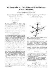
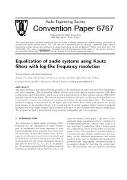
where N is <strong>the</strong>1w0=I 0.8tZcl2 0.60.40.2n " 0 0.1 0.2 0.3 0.4 0.5. 0.6 0.7 0.8 0.9 1NORMALIZED FREQUENCY(a)6. a) Magnitude and h) phase delay responses r,fLagrange interpolatingfilters of length L = 2, 3, 4, 5, and 6 with d = 0.5.-0.1\'\~ ( z = ) z-" for D = 0,1,2, ... N (41)or that for integer values of <strong>the</strong> desired delay <strong>the</strong> approximationerror is set to zero. The solution can be given in anexplicit form ash(n) = n-D-kk0n-kitn,for n =0,1,2 ,... N(42)Naturally, here <strong>the</strong> integer part of D is zero so that D = d.The amplitude and phase delay responses of low-order Lagrangeinterpolators are shown in Fig. 6 for d = 0.5 and N =1,2, ..., 5 (L = 2,3, ..., 6; only <strong>the</strong> fractional part of <strong>the</strong> phasedelay is shown). It is seen that, due to <strong>the</strong> coefficient symmetryfor d = 0.5, <strong>the</strong> even-length filters (L = 2, 4, and 6) areexactly linear-phase, but <strong>the</strong> magnitude responses suffer from<strong>the</strong> zero at W=T. The odd-length filters (L = 3 and 5) havebetter magnitude responses, but <strong>the</strong> phase delays are worse.The = corresponds to linear interpolation be- This magnitude-phase delay tradeoff between even and oddtweentwo In this <strong>the</strong> two coefficients are length filters is similar for o<strong>the</strong>r fractional delay values andfor o<strong>the</strong>r approximation methods as well.h(0) = 1 - D, h(1) = D (43)Lagrange interpolation has several advantages: easy explicitformulas for <strong>the</strong> coefficients, very good response at lowJANUARY 1996 <strong>IEEE</strong> SIGNAL PROCESSING MAGAZINE 41
frequencies, and a smooth magnitude response. The maximumof <strong>the</strong> magnitude response never exceeds unity when<strong>the</strong> delay is near to half <strong>the</strong> filter length. This is important inapplications including feedback. On <strong>the</strong> o<strong>the</strong>r hand, <strong>the</strong> approximationerror is often unnecessarily small at low frequencies,at <strong>the</strong> cost of <strong>the</strong> performance at higher frequencies.Examples of Lagrange interpolator design with different valuesof d are shown in Fig. AS.Lagrange interpolation has been proposed for <strong>the</strong> approximationof a fractional delay independently by Laine [58] andby Liu and Wei [66, 671. In <strong>the</strong> context of multirate filters,<strong>the</strong> Lagrange interpolation scheme has been known for a longtime [24, 80, 971. KO and Lim [48] derived a general maximallyflat frequency-error solution at an arbitrary frequency@=WO, which with <strong>the</strong> choice WO reduces to Lagrange interpolation.The explicit (complex-valued) solution for <strong>the</strong> case ofnonzero WO was presented by Hermanowicz [37]. The maximallyflat FIR FD design has also been discussed by Sivanandet al. [lOl, 1021.In [73], <strong>the</strong> maximally flat interpolator design wasachieved by truncating <strong>the</strong> Taylor series of <strong>the</strong> error function(IS) and by forcing <strong>the</strong> derivatives in <strong>the</strong> Taylor series to bezero at o= 0 0 In [49] it was shown that <strong>the</strong> Lagrange solutionEq. 42 can also be obtained from <strong>the</strong> ideal sinc solution Eq.18 using <strong>the</strong> windowing method. The window coefficients arecomputed using <strong>the</strong> binomial formula.Also o<strong>the</strong>r polynomial interpolation techniques, such assplines [137], have been suggested for fractional delay approximationor interpolation. These techniques are nonoptimalfrom <strong>the</strong> frequency-domain viewpoint. Still, forapplications where good accuracy at high frequencies is notrequired, for example <strong>the</strong> parabolic interpolation technique[27] may be attractive since it can be implemented efficientlywith a third-order FIR filter.One can also construct a mixed approximation method byadding flatness constraints for a certain number of derivativesat in <strong>the</strong> general least squares approximation problem, employing<strong>the</strong> Lagrange multiplier method for <strong>the</strong> constraints asin [54] and [107]. An interesting technique for Taylor seriesapproximation of <strong>the</strong> sinc function was proposed in 11091.Minimax Design of FIR Fractional <strong>Delay</strong> FiltersBoth <strong>the</strong> least squares and <strong>the</strong> maximally flat approximationtechniques have <strong>the</strong> drawback that <strong>the</strong> peak error value in adefined approximation band cannot be controlled explicitly.For example, we may want to design a delay filter whose errorcharacteristics fit in a certain tolerance scheme, i.e., it isdesired to keep <strong>the</strong> peak approximation error in given limits.These kinds of specifications can be met using <strong>the</strong> minimax(Chebyshev) solution which, by definition, minimizes <strong>the</strong>maximum value of <strong>the</strong> error magnitude in <strong>the</strong> range of approximation,or(44)When certain conditions are met, <strong>the</strong> minimax solution isunique and equal to <strong>the</strong> equiripple solution, characterized byan oscillating error curve which attains <strong>the</strong> maxima at acertain number r of frequency points in <strong>the</strong> approximationinterval, i.e.,This is <strong>the</strong> case, for example, in <strong>the</strong> linear-phase approximationfor FIR filters with symmetric or antisymmetric impulseresponse where <strong>the</strong> error function reduces to areal-valued cosine series (with a possible weight function).The equiripple solution can be found by <strong>the</strong> iterative Remezexchange algorithm, as proposed by Parks and McClellan[83]. Unfortunately, Chebyshev approximation problems canusually be solved only by using iterative techniques.However, <strong>the</strong> fractional delay approximation is more troublesomethan <strong>the</strong> case of linear-phase FIR filters since <strong>the</strong>approximating function is complex-valued in general. Advancedalgorithms for complex approximation with minimaxerror characteristics have been presented in 141, [841, 1871,[98], and [41] and <strong>the</strong>y can also be applied to <strong>the</strong> problem athand. However, as <strong>the</strong> design procedures involve iterativealgorithms, <strong>the</strong>y are not suited for applications requiringreal-time coefficient update.A simplifying formulation for <strong>the</strong> minimax complex designin terms of real functions was proposed in [%]. Thecomplex task was split into two real-valued design problemswhich facilitates <strong>the</strong> use of <strong>the</strong> efficient Remez algorithm bya modification to <strong>the</strong> Parks-McClellan program [83]. A newalgorithm capable of full complex approximation was proposedin [41]. However, <strong>the</strong>se algorithms are not much betterfor real-time coefficient update since <strong>the</strong> Remez routine mustbe employed for each delay value.An approach that comes closer to real-time requirementswas proposed by Oetken [SO]. Considering <strong>the</strong> design ofeven-length interpolation FIR filters for sampling rate increaseusing a polyphase structure, <strong>the</strong> amplitude errors of <strong>the</strong>polyphase branches, when made equiripple, are almost exactlyproportional to each o<strong>the</strong>r. In particular, <strong>the</strong> zeros of <strong>the</strong>magnitude error function remain <strong>the</strong> same with high precision.When <strong>the</strong> coefficients of one branch are given, those ofany o<strong>the</strong>r branch can be solved via a set of linear equations.As one of <strong>the</strong> branches corresponds to an exactly linear-phasefilter with a symmetric impulse response, it can be designedoff-line using <strong>the</strong> standard Remez algorithm.Realizing that each polyphase branch actually approximatesa rational fraction of <strong>the</strong> unit delay, <strong>the</strong> method can bedirectly applied to our problem. Let us assume that <strong>the</strong> coefficientsof an Nth-order (or length L = (N + I), L even)symmetric FIR filter are given, <strong>the</strong> amplitude response ofwhich approximates unity in <strong>the</strong> equiripple sense in <strong>the</strong>passband [0, CYT], O
implying thatOetken also observed that <strong>the</strong> amplitude ripple is not <strong>the</strong>same for all <strong>the</strong> polyphase branches (in our case: for allNh(n)LJnRk = e-jakNI2, k = 1,2 ,..., Kfractions of <strong>the</strong> delay). Instead, it depends on <strong>the</strong> fractionaln=O (47) part d in <strong>the</strong> following manner [go]:where NI2 is <strong>the</strong> delay of <strong>the</strong> filter. Assuming that <strong>the</strong> zerosremain <strong>the</strong> same for noninteger values of D as well, <strong>the</strong> filtercoefficients can be solved from Eq. 47 for a chosen total delayD, which is close to Nl2. This can be expressed in matrix formaswhereisaKx(N+ 1)matrixand(494where 61,2 is <strong>the</strong> maximum amplitude ripple of <strong>the</strong> linearphaseprototype filter with <strong>the</strong> delay D = N/2 (= Int(D) + 112)and Sd is <strong>the</strong> ripple of a filter approximating <strong>the</strong> (noninteger)delay D with <strong>the</strong> fractional part, d. Note that <strong>the</strong> amplituderipple is largest in <strong>the</strong> linear-phase case (D = NI2 or d = 0.5)and reduces to zero when <strong>the</strong> fraction approaches an integervalue (d = 0 or d = l), which corresponds to <strong>the</strong> case that <strong>the</strong>impulse response reduces to a unit pulse. The almost-equirippleapproximation computed using <strong>the</strong> Oetken method isillustrated in Fig. A6. The 4-tap FIR filter does not have manyripples, but <strong>the</strong> 10-tap filter responses are seen to be veryclose to equiripple.Relation to Interpolation/Decimation FIR Filters-jDQl ,-jDQ, ,-jDOk T As already discussed above, <strong>the</strong> polyphase structure of decieD=[e ...l(49b) mationlinterpolation filters can be utilized for fractional delayimplementation with fixed steps ([5, 9, 23, 24, 741). ForEquation 48 is a set of K complex equations with L = 2Kexample, in order to break <strong>the</strong> unit delay into Q steps, one canwhich can be expressed as asetdesign a Qth-band lowpass filter with <strong>the</strong> normalized pass-Of equations by equating <strong>the</strong> and parts band width of Q and form <strong>the</strong> Q-branch polyphaseof both sides asby picking up every Qth sample to one branch. It can beshown that each band approximates a fractional delay of <strong>the</strong>(50a) valuewithandPa =[;IPn = [ 3where <strong>the</strong> matrices and vectors contain appropriate cosineand sine elements such that Ea = Cn -j&, and e D= c D-jsD.Note that <strong>the</strong> design scheme can be interpreted as a complexversion of <strong>the</strong> frequency sampling technique [84] where <strong>the</strong>frequency samples are unequally spaced.Hence, one first has to design <strong>the</strong> linear-phase prototypefilter, to find its zero frequencies Qk and <strong>the</strong>n to invert <strong>the</strong>cosine-sine matrix of Eq. 50b. Since <strong>the</strong> zeroes of <strong>the</strong> phaseerror function need not be known with high precision, simplenoniterative search on <strong>the</strong> employed frequency grid is sufficientin general. After that, <strong>the</strong> coefficients of a new filterapproximating any given delay are readily obtained via asingle matrix multiplication. Note that matrix Eq. 50b isindependent of <strong>the</strong> delay D and only needs to be inverted onceoff-line so that <strong>the</strong> approach is suitable for real-time coefficientupdate.D=e-k, k=0,1,2 ,..., Q-IQThe accuracy of approximation depends naturally on <strong>the</strong>length of <strong>the</strong> prototype Qth-band lowpass filter. In order toachieve comparable frequency response for each branch, <strong>the</strong>length of <strong>the</strong> prototype filter should be a multiple of Q. Thelowpass filter should be linear-phase, but it can be designedwith any method. However, <strong>the</strong> optimality of <strong>the</strong> prototypefilter is not shared with <strong>the</strong> branch filters; e.g., equiripplemagnitude characteristic will be lost.The multirate approach is straightforward and well suitedfor table look-up applications. If one is satisfied for example,with Q = 50-step division of <strong>the</strong> unit delay, one simplydesigns a length-501 filter and uses <strong>the</strong> desired length4 filterof <strong>the</strong> set.However, small delay steps and strict specifications for <strong>the</strong>approximation error may result in an FIR filter with hundredsof taps, which makes it impossible to use <strong>the</strong> Parks-McClellanalgorithm for <strong>the</strong> prototype design. In that case, windowingmethods may be used for which <strong>the</strong>re is practically no limitfor <strong>the</strong> filter order. However, as <strong>the</strong>re are several o<strong>the</strong>r simplemethods that provide smaller error, <strong>the</strong> multirate approachnow appears somewhat outdated for this application.For reference, we chose Q = 10 to design prototype filtersof lengths 40 and 100 to provide a set of length-4 andJANUARY 1996 <strong>IEEE</strong> SIGNAL PROCESSING MAGAZINE 43
length-10 FIR filters for 10-step increments of <strong>the</strong> fractionaldelay. The results are shown in Fig. A7. The startling featureis that <strong>the</strong> magnitude approximation error is large for <strong>the</strong> casethat <strong>the</strong> delay is zero. The reason is that <strong>the</strong> impulse responsedoes not have a single nonzero value as it would have in <strong>the</strong>ideal case. This can be alleviated by using <strong>the</strong> “TRICK’,which forces exact zeroes in <strong>the</strong> impulse response [ 1171.However, ra<strong>the</strong>r than for approximation, <strong>the</strong> multirateapproach can be used for implementation of high-qualitywideband FD filters, as proposed in [75]. Using a polyphaseimplementation with two branches <strong>the</strong> accuracy of approximationcan be increased without excessive total delay.Controlling <strong>the</strong> <strong>Delay</strong> of Arbitrary FIR FiltersAbove, we have assumed that <strong>the</strong> fractional delay filter isdesigned exclusively for producing <strong>the</strong> desired delay. However,in time-critical applications this may be impossiblesince an additional FIR filter always introduces some netdelay, as discussed earlier. Instead, it may be more advantageousto control <strong>the</strong> delay of an FIR filter that is alreadyincluded in <strong>the</strong> system. As <strong>the</strong> FIR filter may be adaptive orvariable or for o<strong>the</strong>r reasons its coefficients may not beknown, it is sometimes essential that <strong>the</strong> delay control algorithmbe independent from <strong>the</strong> filter coefficients.1) Fourier Transform Based MethodsWe first present a Fourier transform based delay controlalgorithm which is related to ideal bandlimited interpolationdiscussed in [81]. Let us assume an Nth-order (length L = N+ 1) prototype filter whose frequency response isH,(e”)N= xhp(k)e-jkwk=O (53)If <strong>the</strong> filter is linear-phase, it has constant group delay N/2.Assume that it is desired to change <strong>the</strong> delay by a fractionfrom this nominal value. This is equal to multiplying <strong>the</strong>frequency response by e-1adw orThis is thus <strong>the</strong> desired frequency response. Taking <strong>the</strong>symmetric inverse discrete-time Fourier transform (Eq. 1 1)of Eq. 54, we obtain <strong>the</strong> real-coefficient FIR filter as. EN= hp (k)sinc(n- k - Ad)k=O(55)which is seen to be a weighted sum of sinc functions (Eq. 13)with an infinitely long impulse response and consequentlywith truncation problems. This can be alleviated in <strong>the</strong> usualmanner by employing a suitable time-domain window totruncate h(n). When <strong>the</strong> lengths of h(n) and h,(n) are chosento be <strong>the</strong> same L, <strong>the</strong> solution (Eq. 55) can be given in explicitmatrix form ash= WMSMh,(56)where h and hp are <strong>the</strong> new and <strong>the</strong> prototype FIR coefficientvectors, respectively, and <strong>the</strong> elements of <strong>the</strong> L x L squarematrix Sad areSM,k,l = sinc(k-E - Ad) k,l= 1,2 ,._. L(574and Wad is a diagonal matrix with <strong>the</strong> value of <strong>the</strong> length-Lwindow function as its elements, orNote that <strong>the</strong> length of <strong>the</strong> new h vector can also be chosenlonger or shorter than L by simply adding rows to or canceling<strong>the</strong>m from <strong>the</strong> S4d matrix. Fur<strong>the</strong>rmore, if a fixed step Ad issufficient, one can compute Sad and multiply it by <strong>the</strong> Wadmatrix in advance, which considerably reduces <strong>the</strong> computations.A similar delay control method employing two discreteFourier transforms (DFT) was presented by Adams in [2]. Itis in fact closely related since, by adapting to our notation,<strong>the</strong> two complex DFTs can be packed into a single real-coefficientmatrix Shof <strong>the</strong> form (Eq. 57a) with <strong>the</strong> elementsA sin[n(k -1 - Ad)]k,l=1,2, ... LS‘’k’ = Lsin[.rc(k - I - Ad) / L]The Adams method is thus seen to be a discrete-frequencycounterpart of <strong>the</strong> first method, as <strong>the</strong> essential difference isthat <strong>the</strong> sinc function is replaced by <strong>the</strong> periodic samplingfunction, also known as <strong>the</strong> Dirichlet kernel [11]. The differencein performance of Eq. 57a as compared to Eq. 58 is thusexpected to be small for large L. However, both formulas areclearly more advantageous for practical use than <strong>the</strong> twoexplicit complex DFTs as proposed in [2] (even if <strong>the</strong> FFTalgorithm is employed), since here only real-valued multiplicationsare needed. Fur<strong>the</strong>rmore, <strong>the</strong> matrix (Eq. 58)-as wellas Eq. 57a-has a symmetric Toeplitz structure, which meansthat only L different coefficients are required.For illustration, we approximate <strong>the</strong> equiripple filters ofFig. A6 using this method. The prototype filter was chosen in<strong>the</strong> middle (d = 0.2) and shifted Dolph-Chebyshev windowswith 40 dB ripple were used. From <strong>the</strong> resulting Fig. A8 it isobserved that <strong>the</strong> magnitude and phase delay responses arepoorly preserved for <strong>the</strong> 4-tap filter but fairly good for <strong>the</strong>10-tap filter.2) Matrix Transform Method Basedon Zeros of <strong>the</strong> Error FunctionIt is natural to assume that <strong>the</strong> zeros of <strong>the</strong> error functionremain <strong>the</strong> same not only independently of <strong>the</strong> approximation44 <strong>IEEE</strong> SIGNAL PROCESSING MAGAZINEJANUARY 1996
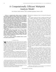
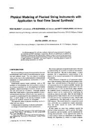
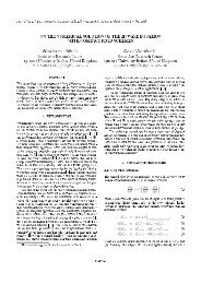
method but also irrespective of <strong>the</strong> amplitude curve approximated.This suggests that <strong>the</strong> Oetken method can be used tocontrol <strong>the</strong> delay of any FIR filter. This is, however, onlypossible when <strong>the</strong> zeros of <strong>the</strong> error function are knownbeforehand so that <strong>the</strong> transformation matrix (which onlydepends on <strong>the</strong> zeros) can be computed.3) Farrow Structure for Fractional <strong>Delay</strong> FIR FiltersA promising technique for efficient implementation of acontinuously variable delay element was proposed by Farrow[29]. This method assumes that <strong>the</strong> filter is designed off-line,but <strong>the</strong> real-time control of <strong>the</strong> delay value is simple andefficient. The basic idea is to design a set of filters approximatinga fractional delay in <strong>the</strong> desired range (e.g., 0s dG1) and <strong>the</strong>n to approximate each coefficient as a Pth-orderpolynomial of d, or'. The Furrow structure for implementation of polynoimiul upproximationoffilter coeflcients.delay control Can be formulated as follows:1) Design a set of Q + 1 FIR filters of <strong>the</strong> (same) chosenorder N approximating in a desired sense <strong>the</strong> ideal nonintegerdelay whose fractional part takes values in <strong>the</strong> desired range[dmi,, dmax]. The values of d can be chosen, for example, on auniform grid as(59)where c,(n) are real-valued approximating coefficients. Thesubscript d is now included to emphasize that each coefficientis a function of <strong>the</strong> fractional delay, d. The transfer functionof <strong>the</strong> filter can be elaborated into <strong>the</strong> formThe result is <strong>the</strong> set of prototype filters with <strong>the</strong> coefficientshd,q(n) for q = 0, 1,2, ..., Q and n = 0, 1,2, ..., N.2) Design <strong>the</strong> polynomial structure approximating <strong>the</strong>coefficients of <strong>the</strong> prototype filters in <strong>the</strong> desired sense so thatDhd,,(n) = xcm(n)d?, q = 0,1,2 ,..., Q; IZ = 0,1,2 ,..., Nm=O (63)where it was definedThe form (Eq. 60) immediately suggests an efficient implementationas a parallel connection of fixed filters withoutput taps weighted by an appropriate power of d (Fig. 7).The sample implementation presented in [29] was designedby employing least squared error criterion over <strong>the</strong>desired frequency band and <strong>the</strong> employed range of d. Also<strong>the</strong> polynomial approximation of <strong>the</strong> filter coefficients wasdone in <strong>the</strong> least squares sense. An excellent tutorial presentationof <strong>the</strong> method with examples and performance analysisis included in [721, when applied to timing adjustment algorithmsin digital receivers.The polynomial approach can readily be generalized foro<strong>the</strong>r filter design techniques as well. In addition to <strong>the</strong> leastsquares method, maximally flat or equiripple approximationcan be employed to design <strong>the</strong> set of prototype filters covering<strong>the</strong> desired range of d. The coefficients of <strong>the</strong> filter set are<strong>the</strong>n approximated separately by <strong>the</strong> polynomial structure ofa desired order. Polynomial interpolation techniques, such asLagrange interpolation, can be realized using <strong>the</strong> Farrowstructure without fur<strong>the</strong>r approximation [27], [ 1261, [130],[135].The design of <strong>the</strong> generalized polynomial structure forNote that <strong>the</strong> design reduces to L = N + 1 separate optimizationproblems: each polynomial approximation is carriedout for a fixed value of n. It is easiest to use least squares curvefitting for this task. According to our experience, second-orderpolynomials with three coefficients are usually sufficient.The resulting coefficients c,(n) are <strong>the</strong>n employed to form<strong>the</strong> transfer functions Cm(z) of <strong>the</strong> subsections, as shown inFig. 7.We applied <strong>the</strong> design method to imitate <strong>the</strong> response of4-tap equiripple approximations of Fig. A6. Second-orderpolynomials (P = 2) were used for coefficient approximation.The results are shown in Figs. 8a and 8b, which show thatboth <strong>the</strong> amplitude and phase delay characteristics are accuratelyreproduced, with hardly any observable deviation from<strong>the</strong> original ones (Figs. A6a and b). Similar results wereobtained for 10-tap filters. Farrow approximation with second-orderpolynomial approximation for coefficients thusprovides an accurate means for practical implementation ofFIR FD filters.The polynomial approximation technique can also be appliedto allpass filters, as will be discussed shortly.Summary of FIR Filter Design and ImplementationTo conclude our discussion of FIR FD filters, we present asummary of <strong>the</strong>se techniques and evaluate <strong>the</strong>ir design complexity.As stated previously, our main interest is in faston-line tuning of <strong>the</strong> fractional delay and thus <strong>the</strong> fast updateof <strong>the</strong> coefficients is of paramount importance.JANUARY 1996 <strong>IEEE</strong> SIGNAL PROCESSING MAGAZINE 45
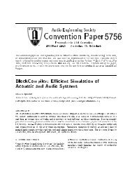
1 3) F ~ O W Structure I N D P set of FIR filters I Polynomial approximation 1 easy and accurate delay control108W9 06tzU2 0.40.2,,50 0.1 0.2 0.3 0.4 0.5 0.6 0.7 0.8 0.9 1NORMALIZED FREQUENCY(41.6nd = 0.5<strong>the</strong> most attractive methods, since only a small number ofmultiplications and additions is needed for coefficient update[52]. Filters of <strong>the</strong> order 1, 2, and 3 are fast to compute andaccurate enough for many applications [42, 120, 121, 1251.Often, <strong>the</strong> coefficients must be updated only for every 5th to50th signal sample so that relatively many operations may bespent for each update.The Farrow polynomial approximation of filter coefficients[29] also offers means for fast coefficient update. Sinceany approximation technique can be used for <strong>the</strong> prototypedesign, polynomial approximation is a highly flexible tooland suitable also for nonstandard applications, where, forexample, an irregular magnitude response is to be maintained.In more complicated filter formulations and design algorithms,real-time coefficient update may be too expensiveunless table lookup techniques are utilized [103, 1061. Thisstrategy is very efficient when <strong>the</strong> table is precompiled so thatproper filter coefficients can be retrieved by table lookup fora finite set of fractional delay values or additional interpolationbetween stored table values.Fractional <strong>Delay</strong> Approximation UsingAllpass Filters0.91 " " " " ' I0 0.1 0.2 0.3 0.4 0.5 0.6 0.7 0.8 0.9 1NORMALIZED FREQUENCY(b). The Farrow polynomial approximation of <strong>the</strong> equiripple FIRdesign ofAd Polynomial order P = 2 andfilter length L = 4. a)magnitude and b) phase delay response.The above discussed FIR design methods are collected in<strong>the</strong> Table above, with information about <strong>the</strong> filter parametersand design complexity. The Lagrange interpolation is one ofIn general, a recursive (IIR) digital filter can meet <strong>the</strong> samefrequency-domain specifications with a smaller number ofmultiplications than an FIR filter. Unfortunately, <strong>the</strong> designof IIR filters with prescribed magnitude and phase (or groupdelay, or phase delay) response is far more complicated thanthat of corresponding FIR filters. The design of FIR filters isgreatly eased by <strong>the</strong> fact that <strong>the</strong> filter coefficients are equalto <strong>the</strong> samples of <strong>the</strong> filter impulse response so that (infull-band approximation) <strong>the</strong> frequency-domain specificationscan be turned into <strong>the</strong> "coefficient domain" by <strong>the</strong>inverse discrete-time Fourier transform. This is not possiblefor recursive filters.46 <strong>IEEE</strong> SIGNAL PROCESSING MAGAZINE JANUARY 1996
Ano<strong>the</strong>r major disadvantage is <strong>the</strong> possible instability ofrecursive filters. In general, <strong>the</strong> obtained solution has to bechecked so that all <strong>the</strong> poles of <strong>the</strong> filter remain within <strong>the</strong>unit circle in <strong>the</strong> z-domain, which makes real-time coefficientupdate difficult.Here we omit <strong>the</strong> problem of magnitude approximation byconsidering only <strong>the</strong> design of allpass filters, a special subclassof recursive filters. (For a report on fractional delay IIRfilter design, see [ 1 131.) Allpass filters have unity magnituderesponse in <strong>the</strong> whole frequency band by definition, whichmeans that one can concentrate on <strong>the</strong> approximation of <strong>the</strong>desired phase (or group delay, or phase delay) characteristics.This reduces <strong>the</strong> available degrees of freedom but also makes<strong>the</strong> design task much easier.The z transfer function of an Nth-order allpass filter is of<strong>the</strong> form!where <strong>the</strong> numerator polynomial is a mirrored version of <strong>the</strong>(supposedly stable) denominator D(z). The coefficients areassumed to be real-valued. The direct form I implementationof <strong>the</strong> allpass filter is shown in Fig. 9. The phase response of<strong>the</strong> allpass filter can be expressed as. Direct form I implementation of an Nth-order allpass filter.wherewheref N 7A=diag[O 1 ... N](69c)Naturally, for <strong>the</strong> phase delay it holds= arctan{$)where c and s are appropriate cosine and sine vectors asdefined in Eq. 30, and a is <strong>the</strong> coefficient vectorwith a0 = 1. The group delay of <strong>the</strong> allpass filter is related tothat of <strong>the</strong> denominator similarly to Eq. 65, orwhere <strong>the</strong> delay of <strong>the</strong> denominator can be expressed asUnfortunately, <strong>the</strong> phase, phase delay, and group delay areall related to <strong>the</strong> filter coefficients in a very nonlinear manner,as <strong>the</strong> above equations show. This means that one cannotexpect as simple design formulas for <strong>the</strong> allpass filter coefficientsas for FIR filters. Instead, one can almost exclusivelyfind only iterative optimization techniques for minimizationof traditional error criteria.In <strong>the</strong> following discussion, we shall review in greaterdetail only <strong>the</strong> simplest allpass design techniques that havesome potential for applications requiring real-time coefficientupdate. Among <strong>the</strong> above delay measures, <strong>the</strong> phase isperhaps <strong>the</strong> most suitable for least squared error design.Consequently, much of <strong>the</strong> following is based on <strong>the</strong> recentresults on least squares phase approximation presented in [60,63,53,77]. These schemes are easy to program and can alsobe modified for approximately equiripple phase error solutions,as well as for corresponding phase delay approximations,in contrast to many o<strong>the</strong>r methods that may be moredifficult to use.JANUARY 1996 <strong>IEEE</strong> SIGNAL PROCESSING MAGAZINE 47
Least Squares Design of Allpass Filters1) Approximate LS Phase Error DesignUsing <strong>the</strong> above notation, <strong>the</strong> phase error (deviation from aprescribed desired phase Oid(w)) can be expressed asequivalent to iteratively solving a set of N linear equations(Appendix C).The easiest way to eliminate <strong>the</strong> denominator is to neglectit, which effectively introduces coefficient-dependentweighting in <strong>the</strong> error measure and thus causes a bias from<strong>the</strong> true least squared error solution. In this case <strong>the</strong> matrix Pis solved aswhereand1p(0) = -[O, (0) + No]2(74)When approximating a noninteger delay D = N +. d, or-Dw= -(N + d>w, <strong>the</strong> last expression reduces to@,d(o)=codP(co) = --2(75)The term Nw is canceled out, since <strong>the</strong> average delay of <strong>the</strong>system is exactly N samples. In [60, 63, 53, 771, severaltechniques were developed to minimize <strong>the</strong> weighted leastsquared phase error, i.e., <strong>the</strong> measurewhere W(o) is a nonnegative weight function. By using linearapproximation for <strong>the</strong> arcus tangent function arctan(x) = x in<strong>the</strong> expression for <strong>the</strong> phase error (Eq. 71), a modified errormeasure can be expressed as(77)Twhere we define new matrices as Sp(w)= spsp and C(o) =cpcpT. If <strong>the</strong> coefficient vector a in <strong>the</strong> denominator wereknown and fixed, this error measure would be a quadraticform expressible aswhere a0 is <strong>the</strong> fixed coefficient vector and <strong>the</strong> matrix P isdefined in an obvious manner. When <strong>the</strong> matrix P is positivedefinite, <strong>the</strong>re exists a unique solution for <strong>the</strong> vector a whichminimizes <strong>the</strong> error measure (Eq. 78). The solution can befound, e.g., by <strong>the</strong> eigenfilter technique [116] which is(79)Due to <strong>the</strong> simple form of p(w), <strong>the</strong> integrals can be solvedin closed form, e.g., if W(w) is chosen piecewise constant.When it is set to W(w) = 1 in <strong>the</strong> approximation band oE[O,OLT], <strong>the</strong> elements of <strong>the</strong> P matrix are obtained as4p> k -n - J {cos[@- 1)ol- cos[(N - (k + 1 + d)ol }do0= 4a{sinc[a(k - Z)] - sinc[a(N - (k + 1 + d))]}k,E=1,2 ,..., L (80)The matrix is seen to have a Toeplitz-plus-Hankel structure.This approximation scheme offers an efficient way to solvefor <strong>the</strong> allpass coefficients, only requiring solution of <strong>the</strong> setof N equations. Using fast algorithms like <strong>the</strong> one proposedin [71], this matrix can be inverted in order of N2 arithmeticoperations instead of N' complexity required for inversion ofa general matrix.The bias from <strong>the</strong> least squares solution can be removedby employing an iterative algorithm such that <strong>the</strong> old coefficientsare used in <strong>the</strong> denominator for weighting, as originallyproposed in [60] and [63]. With this scheme, <strong>the</strong> matrix at <strong>the</strong>qth iteration isFor details, see [63] or [77]. As demonstrated in <strong>the</strong>sereferences, <strong>the</strong> algorithm typically converges to <strong>the</strong> desiredsolution although it cannot be guaranteed.Let us demonstrate both methods by approximating fractionaldelay with second and fifth-order allpass filters. Thephase delay curves obtained using <strong>the</strong> noniterative method(Q. 79) are shown in Figs. B la and b, respectively. Note thatwe show <strong>the</strong> phase delay responses for <strong>the</strong> entire range -0.5sd s0.5 since, unlike FIR filters, no symmetry relations holdfor allpass filters. The phase delay approximation appears to beworse at low frequencies. This is because <strong>the</strong> filter is designedby minimizing <strong>the</strong> phase enror but <strong>the</strong> phase delay (phase dividedby frequency) naturally yields large values when <strong>the</strong> frequencyis small. Fur<strong>the</strong>rmore, it was observed that <strong>the</strong> iterative method(Es. 81) produces essentially equivalent results so that, 111 contrastto phase equalizers [77], in FD filter design <strong>the</strong> noniterativemethod should be preferred in practice.2) LS Phase <strong>Delay</strong> Error Design of Allpass FiltersSince <strong>the</strong> phase delay is defined as <strong>the</strong> negative phase divided48 <strong>IEEE</strong> SIGNAL PROCESSING MAGAZINE JANUARY 1996
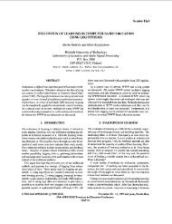
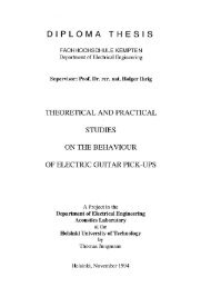
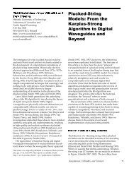
y angular frequency (Eq. lo), <strong>the</strong> LS phase delay error canbe expressed in terms of <strong>the</strong> phase error as followsHence, <strong>the</strong> above phase error solutions can be modified forLS phase delay design by simply introducing an additionalweighting function W(w) = 1h2. For example, in this case<strong>the</strong> P matrix of Eq. 80 becomesPk,l =~~--&cos[(k-l)o]-cos[(N-(k+l+d))w])dw0k,l=1,2 ,..., L(83)whose elements can be determined ei<strong>the</strong>r numerically or byemploying <strong>the</strong> relationcos(ax)- -aSi(ax) - -X (84)where <strong>the</strong> sine integral Si(x) has a fast converging seriesexpansion [ 11:x .sintSi(x) = 1-dt =t(-~)~x'~+'n,o(2n + 1)(2n + I)!t2O(85)The iterative approach is treated similarly. However, aswith phase approximation, also here <strong>the</strong> iterative solutionproduced practically <strong>the</strong> same results, and thus <strong>the</strong>re is noneed for <strong>the</strong> additional complication in FD filter design. Thephase delay curves obtained using <strong>the</strong> noniterative phasedelay approximation technique are shown in Fig. B2. Comparisonto phase approximation (Fig. B 1) demonstrates that<strong>the</strong> phase delay approximation (Fig. B2) is more appropriatewhen <strong>the</strong> design is judged by <strong>the</strong> phase delay curves.Maximally Flat Group <strong>Delay</strong> Designof Allpass FiltersIn 197 1, Thiran proposed an analytic solution for an all-polelowpass filter with a maximally flat group delay response at<strong>the</strong> zero frequency [ 1141. Since <strong>the</strong> group delay of an allpassfilter is twice that of <strong>the</strong> corresponding all-pole filter, <strong>the</strong>all-pole formulas of Thiran can be used for allpass design byusing half of <strong>the</strong> delay value. (In fact, <strong>the</strong> Thiran formulasappear to be much more useful for allpass design, since <strong>the</strong>reis no way to control <strong>the</strong> amplitude response of <strong>the</strong> all-polelowpass filter.) The solution for <strong>the</strong> allpass filter coefficientsapproximating <strong>the</strong> delay D = N + d isI3WQW0-Jar 0.1CL 0.05I 0 0.1 0.2 0.3 0.4 0.5 0.6 0.7 0.8 0.9 1NORMALIZED FREQUENCY10. Phase delay curves of 1,2,3,5, 10, and 20th-order allpassfiltersapproximating fractional delay d = 0.3 (maximally flat groupdelay approximation; only fractional part of <strong>the</strong> delay shown).N!where [:) = ~ is a binomial coefficient. It alwaysk!(N- k)!holds that a0 = 1 so that <strong>the</strong> polynomial is automaticallyscaled as desired.Figure 10 shows <strong>the</strong> phase delay curves of 1,2, 3,5, 10,and 20th-order allpass filters approximating <strong>the</strong> fractionaldelay value d = 0.3. Note that <strong>the</strong> integer parts of <strong>the</strong> delaysare different. The corresponding phase delay responses forfilter orders N = 2 and N = 5 are presented in Fig. B3. It isseen that, even with such low-order filters, <strong>the</strong> delay responseis excellent over a large part of <strong>the</strong> frequency band.In <strong>the</strong> original paper [114] it was shown that for largeenough positive D <strong>the</strong> resulting allpass filter is guaranteed tobe stable, which is a great advantage. As this is <strong>the</strong> onlysolution known to us where <strong>the</strong> coefficients of <strong>the</strong> allpassfilter are obtained in closed form, it seems to be <strong>the</strong> bestchoice for many prac%tical applications.Minimax or Equiripple Design of Allpass FiltersThere exist numerous algorithms that can be used for minimaxor equiripple phase, group delay, or phase delay approximation,e.g., [26, 28, 94, 40, 100, 38, 59, 531. All <strong>the</strong>sealgorithms are iterative and some of <strong>the</strong>m require a goodinitial solution to converge. Instead of reviewing all <strong>the</strong>algorithms in detail, we introduce a straightforward approachfor equiripple phase approximation which can be implementedand used without too much expertise in <strong>the</strong> approximation<strong>the</strong>ory. For a comprehensive monograph on phaseapproximation with allpass filters, see [62].1) Equiripple Phase Error DesignIn [65], an approach for iterative weighting was proposed forapproximately equiripple amplitude design of linear-phaseFIR filters. In [53] and [77], this technique was applied toleast squares phase approximation with allpass filters. Thebasic idea is to use a weighting function in Eq. 81 that alwaysreduces <strong>the</strong> maxima of <strong>the</strong> error curve. This kind of weightingcan be constructed by taking an envelope (i.e., a curve connectinglocal maxima) of <strong>the</strong> phase error function itself. Byraising this envelope curve to a pth power, <strong>the</strong> followingweighting function results:IW(w) = [env 1AO(4-')(w)I]p (87)where env() is <strong>the</strong> envelope function. As seen from Eqs. 76JANUARY 1996 <strong>IEEE</strong> SIGNAL PROCESSING MAGAZINE 49
Design Guide 2: Simplest Allpass FD functions (N = 1, 2, and 3) are given in <strong>the</strong> Table.Filter-Thiran Approximation The plots of <strong>the</strong> phase delay responses of Thiranallpass filters of order N- 1,2,3,5, 10, and 20 in <strong>the</strong>The Thiran method can be viewed as a recur- worst-case approximation (half-sample delay) aresive counterpart of Lagrange interpolation. It presented in Fig. IO-remember that <strong>the</strong> magnitudeis <strong>the</strong> simplest way to design an allpass filter response of an allpass filter is always exactly unityapproximating a given fractional delay D. It is char- in <strong>the</strong> whole frequency band, by definition. It is seenacterized by maximally flat group delay at <strong>the</strong> zero that <strong>the</strong>se low-order filters give an excellent phasefrequency [801. The coefficients are obtained in delay approximation at low frequencies. However,closed form from Eq. (861, or<strong>the</strong> approximation bandwidth grows very slowlywhen <strong>the</strong> filter order is increased. If a low-orderD-N+nThiran allpass filter (e.g., <strong>the</strong> third-order one) is notak = (-I)( T) fifor = 091y2~****good enough for <strong>the</strong> application, it may be better ton = D- ~ N -+ k -+ nuse an LS-based allpass filter design method instead*where N is <strong>the</strong> order of <strong>the</strong> allpass filter. The denominatorcoefficients of low-order allpass transfer,N= 1 -_ --- ____ _______Table : Coefficients of <strong>the</strong> Thiran FD Allpys Filters of Order N = 1,-2,and 3.a2- a3 -~_______ - ___ - __. -_ __-__(D- 1 )(U- 2)/(D +_!)(D + 2) - __ __3(D -2)(D- 3)4D + 1)(D + 2) r -(D-1)(D- 2)(0 - 3)/(D +I )(U-+___nd 87, this solution yields an approximately &+*-norm solution,since <strong>the</strong> weighting function effectively increments <strong>the</strong>power of AO(w) by p from <strong>the</strong> original Lz-solution. When ahigh enough p is chosen (e.g.,p = 50), <strong>the</strong> error curve is veryclose to equiripple. As discussed in [53] and [77], it isadvantageous to increase p in steps larger than one to guaranteefast convergence.2) Equiripple Phase <strong>Delay</strong> Error DesignAs with least squared error design, <strong>the</strong> equiripple phase erroralgorithm can be modified for phase delay design by using<strong>the</strong> envelope of <strong>the</strong> phase delay error for weighting in Eq. 82.This results in <strong>the</strong> following overall weight function at <strong>the</strong> qthiteration:Figure B4 provides examples of <strong>the</strong> equiripple phase delaydesign using <strong>the</strong> iterative algorithm, showing that <strong>the</strong> resultingerror behavior is very close to equiripple. The designalgorithm required ca. 15-30 iteration steps, depending on <strong>the</strong>fractional delay value d.tive design methods.I) Matrix Transform Method Based onZeros of <strong>the</strong> Error FunctionThe phase delay curves of Fig. B4b indicate that <strong>the</strong> zeros of<strong>the</strong> phase error function remain approximately <strong>the</strong> same when<strong>the</strong> fractional delay is changed from -0.5 to 0.5. This suggestsan update algorithm similar to that proposed by Oetken [80]where <strong>the</strong> new coefficients are obtained from <strong>the</strong> prototypefilter via a transformation matrix. Assume that <strong>the</strong> zeros of<strong>the</strong> phase error curve in <strong>the</strong> approximation band wE[O, an](also bandpass approximation is possible) are &, k= 1,2, ...,N. Setting <strong>the</strong> phase response Eq. 65 of <strong>the</strong> filter to approximatedesired values at <strong>the</strong>se points results in an interpolationwhich has a unique solution for an Nth-order allpass filter (fordetails, see [63]). Interpolating <strong>the</strong> phase response -Dw =-(N + D)w yields <strong>the</strong> set of equationsNcq sin[(d + [)ak I = -sin(Qkd) k = 1,2, ..., NI=I (89)which can be given in matrix form asControlling <strong>the</strong> <strong>Delay</strong> of Allpass FiltersUnlike FIR filters, where <strong>the</strong> control of <strong>the</strong> delay of anunknown filter is possible, <strong>the</strong> corresponding devices forallpass filters assume knowledge about a prototype allpassfilter. The methods are in general more complicated thanthose for FIR filters, but never<strong>the</strong>less simpler than <strong>the</strong> itera-wheres ~ , = ~ sin(Qkd) , ~ k = 1,2 ,..., N(91b)50 <strong>IEEE</strong> SIGNAL PROCESSING MAGAZINEJANUARY 1996
2.62.43 2.2WnIi2
On <strong>the</strong> o<strong>the</strong>r hand, one may want to try to find <strong>the</strong> bestsolution for <strong>the</strong> particular application (e.g., in terms of lowimplementation complexity, good magnitude and phase delayresponse in <strong>the</strong> specified frequency band, or flexible on-linetuning of <strong>the</strong> delay). To ease <strong>the</strong> choice we have collected <strong>the</strong>essential FIR and allpass FD filter design methods in Tables1 and2.How do we make <strong>the</strong> basic choice between FIR and allpassfilters? As in <strong>the</strong> general approximation problem, a recursivefilter meets <strong>the</strong> magnitude and phase (delay) specificationswith a smaller number of multiplications. However, <strong>the</strong>remay be additional finite wordlength problems due to rounduffnoise, limit cycles, and possible instability in coefficientquantization (particularly when <strong>the</strong> coefficients are changedon-line). Fur<strong>the</strong>rmore, one may encounter transient problemsin real-time tuning applications [ 1051. The elimination oftransients in variable-coefficient fractional delay allpass filtershas been addressed in 1132-1351.ConclusionsIn this article, we have addressed <strong>the</strong> general problem ofapproximation of a delay that is a fractional part of <strong>the</strong>sampling interval. Both FIR and allpass filter design techniqueshave been reviewed. We have evaluated various optimizationcriteria and design techniques from <strong>the</strong> practicingengineer’s point of view and have tried to provide a goodtutorial in <strong>the</strong> topic. The fractional delay approximation is ageneric problem which is encountered in several fields andapplications of DSP.A set of MATLAB programs for FD filter design is availablevia WWW from http://www.hut.fi/HUT/Acous-tics/fdtools.html or via FTP from helmholtz.hut.fi(130.233.160.51) using anonymous login (directorypub/fdtools).AcknowledgmentsThis work has been in preparation for many years and severalpeople have contributed to its success. Prof. Gerry Cainbrought valuable references to our attention. Dr. Floyd Gardneras well as Prof. Heinrich Meyr and Dr. Gerd Ascheidgenerously provided advance manuscripts of his paper 1321and of <strong>the</strong>ir book [72], respectively. The following individualsprovided insightful and helpful comments, which is gratefullyacknowledged here: Dr. Tsuhan Chen, Mr. PerttiJarvensivu, Mr. Kari Jarvinen, Dr. Kari Kalliojiirvi, Dr. PeterKootsookos, Dr. Markus Lang, Prof. Henrique Malvar, Mr.Dana Massie, Prof. Truong Nguyen, and Prof. Seppo Ovaska.Thanks to Mrs. Elspeth Murphy for checking <strong>the</strong> language of<strong>the</strong> manuscript. Also <strong>the</strong> anonymous reviewers providedmany insightful comments which improved <strong>the</strong> quality of <strong>the</strong>article. Special thanks are due to Dr. Jonathan Mackenzie forfruitful discussions on <strong>the</strong> title of this article.T. I. Laakso is with <strong>the</strong> University of Westminster, Schoolof Electronic and Manufacturing Systems Engineering, Lon-don, U.K., and Helsinlu University of Technology, Laboratoryof <strong>Signal</strong> <strong>Processing</strong> and Computer Technology, Espoo,Finland, on leave from Nokia Research Center, Helsinki,Finland. V. Valimiiki, M. Karjalainen, and U.K. Laine arewith Helsinki University of Technology, Laboratory ofAcoustics and Audio <strong>Signal</strong> <strong>Processing</strong>, Espoo, Finland.References1. M. Abramowitz and I. A. Stegun, Handbook of Ma<strong>the</strong>matical Functions.New York: Dover Publications, 1972.2. J. W. Adams, Altemate approach to digital phase shift filters, in Proc. Int.Symp. <strong>Signal</strong> <strong>Processing</strong>: Theories, Implementations and Applications (IS-SPA-87), pp. 160-165, Brisbane, Australia, Aug. 24-28,1987.3. R. Adam and T. Kwan, Theory and VLSI architectures for asynchronoussample-rate converters, L Audio Eng. Soc., vol. 41, no. 7/8, pp. 539-555,Jul./Aug. 1993.4. A. Alkhairy, K. Christian, and J. Lim, Design of FIR filters by complexChebyshev approximation, in Proc. <strong>IEEE</strong> Int. Con$ Acoust. Speech <strong>Signal</strong><strong>Processing</strong> (ICASSP-91), vol. 3, pp. 1985-1988, Toronto, Canada, May1417, 1991.5. R. Ansari and B. Liu, Efficient sampling rate conversion using recursive(IIR) digital filters, <strong>IEEE</strong> Trans. Acoust. Speech <strong>Signal</strong> <strong>Processing</strong>, vol. 31,no. 6, pp. 1366-1373, Dec. 1983.6. R. Ansari and B. Liu, Multirate signal processing, in S. K. Mitra and J. F.Kaiser (eds.), Handbook of Digital <strong>Signal</strong> <strong>Processing</strong>. New York: JohnWiley & Sons, 1993, pp. 981-1084.7. J. Armstrong and D. Strickland, Symbol synchronization using signalsamples and interpolation, <strong>IEEE</strong> Trans. Communications, vol. 41, no. 2, pp.318-321, Feb. 1993.8. G. Ascheid, M. Oerder, J. Stahl, and H. Meyr, An all-digital receiverarchitectwe for bandwidth efficient transmission at high data rates, <strong>IEEE</strong>Trans. Communications, vol. 37, pp. 804-813, Aug. 1989.9. M. G. Bellanger, G. Bonnerot, and M. Coudreuse, Digital filtering bypolyphase network application to sample-rate alteration and filter banks,<strong>IEEE</strong> Trans. Acoust. Speech <strong>Signal</strong> <strong>Processing</strong>, vol. 24, no 2, pp. 199-126,April 1976.10. K. Bucket and M. Moeneclaey, The effect of interpolation on <strong>the</strong> BERperformance of narrowband BPSK and (0)QPSK on Rician-fading channels,<strong>IEEE</strong> Trans. Communications, vol. 42, no. 11, pp. 2929-2953, Nov. 1994.11. C. S. Burrus and T. W. Parks, DFT/FFT and Convolution Algorithms.New York: John Wiley & Sons, 1985.12. C. S. Burrus, A. W. Sowieto, and R. A. Gopinath, Least squared errorFIR fdter design with transition bands, <strong>IEEE</strong> Trans. <strong>Signal</strong> <strong>Processing</strong>, vol.40, no. 6, pp. 1327-1340, June 1992.13. C. S. Bms, Multiband least squares FIR filter design, <strong>IEEE</strong> Trans.<strong>Signal</strong> <strong>Processing</strong>, vol. 43, no. 2, pp. 412-421, Feb. 1995.14. G. D. Cain and A. Yardim, The tunable fractional delay filter: passportto finegrain delay estimation, Invited Paper presented at Fourth Cost 229Workshop on Adaptive Methods and Emergent Techniques for <strong>Signal</strong> <strong>Processing</strong>and Communications, pp. 9-24, Ljubljana, Slovenia, April 57,1994.Also in Electrutechnical Review, Ljubljana, Slovenia, vol. 61, no. 4, pp.232-242, 1994.15. G. D. Cain, N. P. Murphy, and A. Tarczynski, Evaluation of severalvariable FIR fractional-sample delay filters, in Proc. <strong>IEEE</strong> Int. Con$ Acoust.Speech <strong>Signal</strong> <strong>Processing</strong> (ICASSP-94), vol. 3, pp. 621-624, Adelaide,Australia, April 19-22, 1994.16. G. D. Cain, A. Yardim, and P. Henry, New FIR fractional delayors foreffective signal interpolation, in Proc. DSP-94 ESA Workshop on DSP forSpace Applications, pp. 42-49, London, Sept. 26-28, 1994.17. G. D. Cain, A. Yardim, and P. Henry, Offset windowing for FIRfractional-sample delay, in Proc. <strong>IEEE</strong> Int. Con$ Acoust. Speech and <strong>Signal</strong><strong>Processing</strong> (ICASSP-95), vol. 2, pp. 1276-1279, Detroit, Michigan, May9-12, 1995.18. T. Chen, H. P. Graf, and K. Wang, Speech-assisted video processing:interpolation and low-bitrate coding, in Proc. 28th Annual Asilomar Con$on <strong>Signal</strong>s, Systems, and Computers, pp. 975-979, Pacific Grove, California,Oct. 1994.52 <strong>IEEE</strong> SIGNAL PROCESSING MAGAZINE JANUARY 1996
19. T. Chen, H. P. Graf, and K. Wang, Lip-synchronization using speech-assistedvideo processing, <strong>IEEE</strong> <strong>Signal</strong> <strong>Processing</strong> Letters, vol. 2, no. 4, pp.57-59, April 1995.20. T. Chen, personal communication with T. I. Laakso, May 10, 1995.21. P. R. Cook, TBone: an interactive waveguide brass instrument syn<strong>the</strong>sisworkbench for <strong>the</strong> NeXT machine, in Proc. Int. Computer Music Conk(ICMC-91), pp. 297-299, Montreal, Canada, Oct. 16-20,1991.22. P. R. Cook, A meta-wind-instrument physical model, and a meta-controllerfor real time performance control, in Proc. Int. ComputerMusic Con5(ICMC-92), pp. 273-276, San Jose, California, Oct. 14-18, 1992.23. R. E. Crochiere, L. R. Rabiner, and R. R. Shively, A novel implementationofdigital phase shifters, Bell Syst. Tech. J., vol. 54, no. 8, pp. 1497-1502,Oct. 1975.24. R. E. Crochiere and L. R. Rabiner, Multirute Digital <strong>Signal</strong> <strong>Processing</strong>.Englewood Cliffs, New Jersey: Prentice-Hall, 1983.25. S. Cucchi, F. Desinan, G. Parladori, and G. Sicuranza, DSP implementationof arbitrary sampling frequency conversion for high quality soundapplication, in Proc. <strong>IEEE</strong> Int. Conk Acoust. Speech <strong>Signal</strong> <strong>Processing</strong>(ICASSP-91), vol. 5, pp. 3609-3612, Toronto, Canada, May 14-17, 1991.26. A. G. Deczky, Equiripple and minimax (Chebyshev) approximations forrecursive digital filters, <strong>IEEE</strong> Trans. Acoust. Speech <strong>Signal</strong> <strong>Processing</strong>, vol.22, pp. 98-111, April 1974.27. L. Erup, F. M. Gardner, and F. A. Harris, Interpolation in digitalmodems-part 11: implementation and performance, <strong>IEEE</strong> Trans. Comm., vol.41, no. 6, pp. 998-1008, June 1993.28. K.-P. Estola and T. Saramiiki, A new method for designing equirippleerror group delay filters, in Proc. ZEEElnt. Symp. CircuitsSyst. (ISCAS-85),vol. 1, pp. 271-274, Kyoto, Japan, June 5-7, 1985.29. C. W. Farrow, A continuously variable digital delay element, in Proc.<strong>IEEE</strong> Int. Symp. Circuits Syst. (ISCAS-88), vol. 3, pp. 2641-2645, Espoo,Finland, June 6-9, 1988.30. F. M. Gardner, Timing adjustment via interpolation in digital demodulators,European Space Agency Report, Contract 8022/88/NL/DG, PaloAlto, California, June 1990.3 1. F. M. Gardner and L. Erup, Interpolation for timing adjustment in digitalmodems, in Proc. Second Int. Workshop on Digital <strong>Signal</strong> <strong>Processing</strong>Techniques Applied to Space Communications (DSP-90), ESA-WPP-0191-2, Politecnico di Torino, Turin, Italy, Sept. 24-25, 1990.32. F. M. Gardner, Interpolation in digital modems-part I: fundamentals,<strong>IEEE</strong> Trans. Comm., vol. 41, no. 3, pp. 502-508, Mar. 1993.33. M. C. Gill and L. P. Sabel, On <strong>the</strong> use of interpolation in digitaldemodulators, Australian Telecommunications Review, vol. 27, no. 2, pp.25-31, 1993.34. G. H. Golub and C. F. Van Loan, Matrix Computations. Second Edition.Baltimore, Maryland Johns Hopkins University Press, 1989.35. F. J. Harris, On <strong>the</strong> use of windows for harmonic analysis with <strong>the</strong> discreteFourier transform, Proc. <strong>IEEE</strong>, vol. 66, no. 1, pp. 51-83, Jan. 1978.36. S. Haykin, Adaptive Filter Theory. Englewood Cliffs, New Jersey:Prentice-Hall, 1986.37. E. Hermanowicz, Explicit formulas for weighting coefficients of maximallyflat tunable FIR delayers, Electronics Letters, vol. 28, no. 20, pp.1936-1937,24th Sept. 1992.38. M. Ikehara, M. Funaishi, and H. Kuroda, Design of all-pass networksusing Remez algorithm, in Proc. <strong>IEEE</strong> In/. Symp. Circuits Syst. (ISCAS-91),pp. 364-367, Westin Plaza, Singapore, June 11-14, 1991.39. D. A. Jaffe and J. 0. Smith, Extensions of <strong>the</strong> Karplus-Strong pluckedstring algorithm, ComputerMusic J., vol. 7, no. 2, pp. 56-69,1983. Reprintedin C. Roads (ed.), The Music Machine. Cambridge, Massachusetts: MITPress, 1989, pp. 481-494.40. Z. Jing, A new method for digital allpass filter design, <strong>IEEE</strong> Trans.Acoust. Speech <strong>Signal</strong> <strong>Processing</strong>, vol. 35, pp. 1557-1564, Nov. 1987.41. L. J. Karam and J. H. McClellan, Complex Chebyshev approximationfor FIR filter design, <strong>IEEE</strong> Trans. Circuits Syst. -It Analog and Digital <strong>Signal</strong><strong>Processing</strong>, vol. 42, no. 3, pp. 207-216, Mar. 1995.42. M. Karjalainen and U. K. Laine, A model for real-time sound syn<strong>the</strong>sisof guitar on a floating-point signal processor, in Proc. <strong>IEEE</strong> In/. Con$ Acoust.Speech <strong>Signal</strong> <strong>Processing</strong> (ICASSP-91), vol. 5, pp. 3653-3656, Toronto,Canada, May 14-17,1991,43. M. Karjalainen and V. Valimiiki, Model-based analysis/syn<strong>the</strong>sis of <strong>the</strong>acoustic guitar, in Proc. Stockholm Music Acoustics Conk (SMAC 93), pp.443-447, Stockholm, Sweden, July 28-Aug. 1,1993.44. M. Karjalainen, V. Valimiiki, and Z. Jihosy, Towards high-qualitysyn<strong>the</strong>sis of <strong>the</strong> guitar and string instruments, in Proc. Int. Computer MusicConf. (ICMC-93), pp. 56-63, Tokyo, Japan, Sept. 10-15,1993.45. K. Karplus and A. Strong, Digital syn<strong>the</strong>sis of plucked-string and drumtimbres, Computer Music J., vol. 7, no. 2, pp. 43-55, 1983. Reprinted in C.Roads (ed.), The Music Machine. Cambridge, Massachusetts: MIT Press,1989, pp. 467-479.46. S. Kay, Some results in linear interpolation <strong>the</strong>ory, <strong>IEEE</strong> Trans. Acoust.Speech <strong>Signal</strong> <strong>Processing</strong>, vol. 31, pp. 746-749, June 1983.47. P. Knutson, D. McNeely, and K. Horlander, An optimal approach todigital raster mapper design, <strong>IEEE</strong> Trans. ConsumerElectronics, vol. 37, no.4, pp. 746-752, Nov. 1991.48. C. C. KO and Y. C. Lim, Approximation of a variable-length delay lineby using tapped delay line processing, <strong>Signal</strong> <strong>Processing</strong>, vol. 14, no. 4, pp.363-369, June 1988.49. P. Kootsookos and R. C. Williamson, FIR approximation of fractionalsample delay systems, <strong>IEEE</strong> Trans. Circuits Syst. -II: Analog and Digital<strong>Signal</strong> <strong>Processing</strong>, vol. 43, no. 2, Feb. 1996.50. P. Kroon and B. S. Atal, Pitch prediction with high temporal resolution,in Proc. <strong>IEEE</strong> Int. Con$ Acoust. Speech <strong>Signal</strong> <strong>Processing</strong> (ICASSP-90),vol. 2, pp. 661-664, Albuquerque, New Mexico, April 3-6, 1990.51.P. KroonandB. S.Ata1,On<strong>the</strong>useofpitchpredictorswithhightemporalresolution, <strong>IEEE</strong> Trans. <strong>Signal</strong> <strong>Processing</strong>, vol. 39, no. 3, pp. 733-735, Mar.1991.52. T. I. Laakso, V. Viilimtiki, M. Karjalainen, and U. K. Laine, Real-timeimplementation techniques for a continuously variable digital delay inmodeling musical instruments, in Proc. Int. Computer Music Con5 (ICMC-92), pp. 140-141, San Jose, California, Oct. 14-18, 1992.53. T. I. Laakso, T. Q. Nguyen, and D. Koilpillai, Designing allpass filtersusing <strong>the</strong> eigenfilter method, in Proc. <strong>IEEE</strong> Int. Con5 Acoust. Speech <strong>Signal</strong><strong>Processing</strong> (ICASSP-93), vol. 3, pp. 77-80, Minneapolis, Minnesota, April27-30, 1993.54. T. I. Laakso, S. J. Ovaska, Optimal polynomial predictors with applicationspecific fixed prefilters, in Proc. <strong>IEEE</strong>Int. Symp. Circuits Syst. (ISCAS-93), vol. 1, pp. 351-354, Chicago, Illinois, May 3-6, 1993.55. T. I. Laakso, V. Valim&i, and J. Henriksson, Tunable downsamplingusing fractional delay filters with applications to digital TV transmission, inProc. <strong>IEEE</strong> Znt. Con$ Acoust. Speech <strong>Signal</strong> <strong>Processing</strong> (ICASSP-95), vol.2, pp. 1304-1307, Detroit, Michigan, May 9-12, 1995.56. T. I. Laakso, T. Saramiiki, and G. D. Cain, Asymmetric Dolph-Chebyshev,Saramiiki, and transitional windows for fractional delay FIR filterdesign, in Proc. 38th Midwest Symposium on Circuits and Systems(MWSCAS-95), Rio de Janeiro, Brazil, Aug. 13-16, 1995.57. R. Lagadec, D. Pelloni, and D. Weiss, A 2-channel, 16-bit digitalsampling frequency converter for professional digital audio, in Proc. <strong>IEEE</strong>Int. Con$ Acoust. Speech <strong>Signal</strong> <strong>Processing</strong> (ICASSP-82), vol. 1, pp. 93-96,Paris, France, May 3-5, 1982.58. U. K. Laine, Digital modelling of a variable length acoustic tube, in Proc.Nordic Acoustical Meeting (NAM-88), pp. 165-168, Tampere, Finland, June15-17, 1988.59. M. Lang, Optimal weighted phase equalization according to <strong>the</strong> L norm,<strong>Signal</strong> <strong>Processing</strong>, vol. 27, no. 1, pp. 87-98, April 1992.60. M. Lang and T. Laakso, Design of allpass filters for phase approximationand equalization using LSEE error criterion, in Proc. <strong>IEEE</strong> Int. Symp.Circuits Syst. (ISCAS-92), pp. 2417-2420, San Diego, California, May10-13, 1992.61. M. Lang and J. Bamberger, Nonlinear phase FIR filter design withminimum LS error and additional constraints, in Proc. ZEEE Int. Con5Acoust. Speech <strong>Signal</strong> <strong>Processing</strong> (ICASSP-93), vol. 3, pp. 57-60. Minneapolis,Minnesota, April 27-30, 1993.62. M. Lang, Beitrage zur Phasenapproximation mit Allpassen (Contributionsto phase approximation by allpass filters, in German). Dr. Tech. Thesis,Erlangen, Germany: Lehrstuhl fur Nachrichtentechnik, University of Erlangen,1993.63. M. Lang and T. I. Laakso, Simple and robust method for <strong>the</strong> design of allpassfilters using least-squares phase error criterion, <strong>IEEE</strong> Trans. Circuits Syst.-II:Analog and Digital <strong>Signal</strong> <strong>Processing</strong>, vol. 41, no. 1, pp. 40-48, Jan. 1994.64. M. Lang, personal communication with T. I. Laakso, Aug. 1995.JANUARY 1996 <strong>IEEE</strong> SIGNAL PROCESSING MAGAZINE 53
65. Y. C. Lim, J.-H. Lee, C. K. Chan, and R.-H. Yang, A weighted leastsquaresalgorithm for quasi-equiripple FIR and W digital filter design, <strong>IEEE</strong>Trans. <strong>Signal</strong> <strong>Processing</strong>, vol. 40, no. 3, pp. 551-558, Mar. 1992.66. G.-S. Liu and C.-H. Wei, Programmable fractional sample delay fdterwith Lagrange interpolation, Electronics Letters, vol. 26, no. 19, pp. 1608-1610, 13th Sept. 1990.67. G.3. Liu and C.-H. Wei, A new variable fractional sample delay filterwith nonlinear interpolation, <strong>IEEE</strong> Trans. Circuits Syst.-II: Analog andDigital <strong>Signal</strong> <strong>Processing</strong>, vol. 39, no. 2, pp. 123-126, Feb. 1992.68. J. S. Marques, J. M. Tribolet, 1. M. Trancoso, andL. B. Almeida, Pitchprediction with fractional delays in CELP coding, in Proc. European Con$Speech Communications and Technology (EUROSPEECH-89), vol. 2, pp.509-512, Paris, France, September 1989. Also: J. S. Marques,I. M. Trancoso,J. M. Tribolet, and L. B. Almeida, Improved pitch prediction with fractionaldelays in CELP coding, in Proc. <strong>IEEE</strong> Int. Con$ Acoust. Speech <strong>Signal</strong><strong>Processing</strong> (ICASSP-YO), vol. 2, pp. 665-668, Albuquerque, New Mexico,April 3-6,1990.69. The MATLAB User’s Guide. South Natick, Massachusetts: The Math-Works, Inc., 1989.70. Y. Medan, Using super resolution pitch in waveform speech coders, inProc. <strong>IEEE</strong> Int. Con5 Acoust. Speech <strong>Signal</strong> <strong>Processing</strong> (ICASSP-91), vol.1, pp. 633-636, Toronto, Canada, May 2-5, 1991.71. G. A. Merchant and T. W. Parks, Efficient solution of Toeplitz-plus-Hankel coefficient matrix system of equations, <strong>IEEE</strong> Trans. Acoust. Speech<strong>Signal</strong> <strong>Processing</strong>, vol. 30, pp. 40-44, Feb. 1982.72. H. Meyr and G. Ascheid, Synchronization in Digital Communications,vol. 2, to be published.73. S. Minocha, S. C. Dutta Roy, and B. Kumar, A note on <strong>the</strong> FIRapproximation of a fractional sample delay, Int. J. Circuit Theory and Appl.,vol. 21, no. 3, pp. 265-274, May-June 1993.74. F. Mintzer, On half-band, third-band, and Nth-band FIR filters and <strong>the</strong>irdesign, <strong>IEEE</strong> Trans. Acoust. Speech <strong>Signal</strong> <strong>Processing</strong>, vol. 30, pp. 734-738,Oct. 1982.75. N. P. Murphy, A. Krukowski, and 1. Kale, Implementation of widebandinteger and fractional delay element, Electronics Letters, vol. 30, no. 20, pp.1658-1659,29th Sept. 1994.76. T. Q. Nguyen, The design of arbitrary FIR digital filters using <strong>the</strong>eigenfilter method, <strong>IEEE</strong> Trans. <strong>Signal</strong> <strong>Processing</strong>, vol. 41, no. 3, pp.1128-1139, Ma. 1993.77. T. Q. Nguyen, T. I. Laakso, and R. D. Koilpillai, Eigenfilter approach for<strong>the</strong> design of allpass filter approximating a given phase response, <strong>IEEE</strong>Trans. <strong>Signal</strong> <strong>Processing</strong>, vol. 42, no. 9, pp. 2257-2263, Sept. 1994.78. C. O’Neill, B. Murray, and A. D. Fagan, An efficient algorithm for pitchprediction using fractional delays, in Proc. Sixth European <strong>Signal</strong> <strong>Processing</strong>Con5 (EUSIPCO-92), vol. 1, pp. 319-322, Brussels, Belgium, Aug. 24-27,1992.79. G. Oetken, T. W. Parks, and H. W. Schiipler, New results in <strong>the</strong> designof digital interpolators, <strong>IEEE</strong> Trans. Acoust. Speech <strong>Signal</strong> <strong>Processing</strong>, vol.23, no. 3, pp. 301-309, June 1975.80. G. Oetken, A new approach for <strong>the</strong> design of digital interpolating filters,<strong>IEEE</strong> Trans. Acoust. Speech <strong>Signal</strong> <strong>Processing</strong>, vol. 27, no. 6, pp. 637-643,Dec. 1979.81. A. Papoulis, <strong>Signal</strong> Analysis. New York: McGraw-Hill, 1977.82. S. Park, G. Hillman, and R. Robles, A novel structure for real-time digitalsample-rate converters with finite precision error analysis, in Proc. <strong>IEEE</strong> Int.Con5 Acoust. Speech<strong>Signal</strong><strong>Processing</strong> (ICASSP-91), vol. 5,pp. 3613-3616,Toronto, Canada, May 14-17, 1991.83. T. W. Parks and J. H. McClellan, A program for <strong>the</strong> design of linear phasefinite impulse response digital filters, <strong>IEEE</strong> Trans. Audio Electroacoust., vol.AU-20, pp. 195-199, Aug. 1972.84. T. W. Parks and C. S. Burrus, Digital Filter Design. New York: JohnWiley &Sons, 1987.85. S.-C. Pei and J.-3. Shyu, Eigen-approach for designing FIR filters andallpass phase equalizers with prescribed magnitude and phase response,<strong>IEEE</strong> Trans. Circuits Syst. -U: Aimlog and Digital <strong>Signal</strong> <strong>Processing</strong>, vol. 39,no. 3, pp. 137-146, Mar. 1992.86. L. E. Pellon, A double Nyquist digital product detector for quadraturesampling, <strong>IEEE</strong> Trans. <strong>Signal</strong> <strong>Processing</strong>, vol. 40, no. 7, pp. 1670.1681, July1992.87. K. Preuss, On <strong>the</strong> design of FIR filters by complex approximation, <strong>IEEE</strong>Trans. Acoust. Speech <strong>Signal</strong> <strong>Processing</strong>, vol. 37, pp. 702-712, May 1989.88. M. F. Pyfer and R. Ansari, The design and application of optimal FIRfractional-slope phase filters, in Proc. <strong>IEEE</strong> Int. Con$ Acoust. Speech <strong>Signal</strong><strong>Processing</strong> (ICASSP-87), vol. 2, pp. 896-899, Dallas, Texas, April 6-9,1987.89. R. P. Ramachandran and P. Kabal, Pitch prediction filters in speechcoding, <strong>IEEE</strong> Trans. Acoust. Speech and <strong>Signal</strong> <strong>Processing</strong>, vol. 37, no. 4,pp. 467478, April 1989.90. V. Ramachandran, C. S. Gargour, and M. Ahmadi, Generation of digitaltransfer functions of <strong>the</strong> FIR type approximating P’q, in Proc. <strong>IEEE</strong> Int.Symp. Circuits Syst. (ISCAS-90), vol. 4, pp. 3260-3262, New Orleans,Louisiana, May 1-3, 1990.91. T. A. Ramstad, Sample-rate conversion by arbitrary ratios, in Proc. <strong>IEEE</strong>Int. Con$ Acoust. Speech <strong>Signal</strong> <strong>Processing</strong> (ICASSP-82), vol. 1, pp. 101-104, Paris, France, May 3-5, 1982.92. T. A. Ramstad, Digital methods for conversion between arbitrary samplingfrequencies, <strong>IEEE</strong> Trans. Acoust. Speech <strong>Signal</strong> <strong>Processing</strong>, vol. 32,no. 3, pp. 577-591, June 1984.93. P. A. Regalia, Special filter designs, in S. K. Mitra and J. F. Kaiser (eds.),Handbook for Digital <strong>Signal</strong> <strong>Processing</strong>. New York: John Wiley & Sons,1993, pp. 948-953.94. M. Renfors and T. Saramiki, A class of approximately linear phase digitalfilters composed of allpass subfilters, in Proc. <strong>IEEE</strong> Int. Symp. Circuits Syst.(ISCAS-86), pp. 678-681, San Jose, California, May 1986.95. L. P. Sabel, A. Yardim, and G. D. Cain, An analysis of matched filterinterpolator performance for digital demodulators, presented at ThirdUKLAustraEian Int. Symp. on DSP for Communication Systems, Universityof Warwick, Coventry, U.K., Dec. 12-14,1994.96. L. P. Sabel, G. D. Cain, A. Yardim, and T. Laakso, Effects of delay rootraised-cosine filters on <strong>the</strong> performance of digital demodulators, in Proc. Int.Con5 on Telecommunications (ICT’95), pp. 75-79, Bali, Indonesia, April3-5, 1995.97. R. W. Schafer and L. R. Rabiner, A digital signal processing approach tointerpolation, Proc. <strong>IEEE</strong>, vol. 61, no. 6, pp. 692-702, June 1973.98. M. Schulist, Improvements of a complex FIR filter design algorithm,<strong>Signal</strong> <strong>Processing</strong>, vol. 20, no. 1, pp. 81-90, May 1990.99. H. W. Schiipler, Digitale <strong>Signal</strong>verarbeitung 11, Skriptuin Nr. 4 (Lecturenotes on DSP no. 4, in German). Erlangen, Germany: Lehrstuhl furNachrichtentechnik, Universitlit Erlangen-Numberg, 1984.100. H. W. SchiiPler and J. Weith, On <strong>the</strong> design of recursive Hilberttransformers, in Proc. <strong>IEEE</strong> Int. Con$ Acoust. Speech <strong>Signal</strong> <strong>Processing</strong>(ICASSP-87), vol. 2, pp. 876-879, Dallas, Texas, April 6-9, 1987.101. S. Sivanand, J. F. Yang, and M. Kaveh, Focusing filters for wide-banddirection finding, <strong>IEEE</strong> Trans. <strong>Signal</strong> <strong>Processing</strong>, vol. 39, no. 2, pp. 437-445,Feb. 1991.102. S. Sivanand, Variable-delay implementation using digital FIR filters, inProc. Int. Con$ <strong>Signal</strong> <strong>Processing</strong> Appl. and Tech. (ICSPAT-92), pp. 1238-1243, Boston, Massachusetts, Nov. 2-5, 1992.103. J. 0. Smith and P. Gossett, A flexible sampling-rate cohversion method,in Proc. <strong>IEEE</strong> Int. Con$ Acoust. Speech <strong>Signal</strong> <strong>Processing</strong> (ICASSP-84), vol.2, pp. 19.4.1-19.4.4, San Diego, California, Mar. 19-21, 1984.104. J. 0. Smith and B. Friedlander, Adaptive interpolated time-delayestimation, <strong>IEEE</strong> Trans. Aerospace and Electronic Systems, vol. AES-21,no. 3, pp. 180-199, Mar. 1985.105.3.0. Smith, J. 0. SmithIIIcomments on Sullivan Karplus-Strong article,ComputerMusic Joumal, vol. 15, no. 2, pp. 10-11, 1991.106. J. 0. Smith, Bandlimited interpolation-introduction and algorithm,unpublished manuscript, Nov. 5, 1992.107. P. Steffen, On digital smoothing filters: a brief review of closed formsolutions and two new approaches, Circuits, Systems, and <strong>Signal</strong> <strong>Processing</strong>,vol. 5, no. 2, pp. 187-210, 1986.108. H. W. Struhe, Sampled-data representation of a nonuniform losslesstube of continuously variable length, J. Acoust. Soc. Am., vol. 57, no. 1, pp.256-257, Jan. 1975.109. R. Sudhakar, R. C. Agarwal, and S. C. Dutta Roy, Time domaininterpolation using differentiators, <strong>IEEE</strong> Trans. Acoust. Speech and <strong>Signal</strong><strong>Processing</strong>, vol. 30, no. 6, pp. 992-997, Dec. 1982.(continued on page 60)54 <strong>IEEE</strong> SIGNAL PROCESSING MAGAZINE JANUARY 1996
~ dAppendix A. Examples of FD FIR Filters1.101 ' " " " "0 0.1 0.2 0.3 0.4 0.5 0.6 0.7 0.8 0.9 10 0.1 0.2 0.3 04 0.5 0.6 0.7 0.8 09 1Normalized Frequency(b)10.84.49 0.6inI" 0.4r d=0.5o.2 i01 " " " ' ' "0 0.1 0.2 0.3 0.4 0.5 0.6 0.7 0.8 0.9 1Normalized Frequency4.13.91 " " " " '0 0.1 0.2 0.3 04 0.5 0.6 0.7 0.8 0.9 1Normalized FrequencyI ' " ' ~ ' ' " I45d=e5= 0 44,42 4.3 - = O3z4,1E m 4,2d =0.2d.01d=O0 0 1 0.2 0.3 0.4 0.5 0.6 0.7 0.8 0.9NORMALIZED FREQUENCY3 9 l , , , ' I , ' I I0 0.1 02 0.3 0.4 0.5 0.6 0.7 0.8 0.9 1NORMALIZED FREQUENCY(d (d)Fig. A2. Windowed LS HR design. Fractionally shifted Dolph-Chebyshev window with 40 dB sidelobe ripple. L = 4: (a)Magnitude and (b) phase delay response. L = 10: (c) Magnitude and (d) phase delay response.JANUARY 1996<strong>IEEE</strong> SIGNAL PROCESSING MAGAZINE 55
1.4-0.9b " " " " ,0.1 0.2 0.3 0.4 0.5 0.6 07 0.8 0.9 1NORMALIZED FREQUENCYfb)10.e4,4d =0.4w2 0.6tz$ 0.40.2< 2 4,1 d =0.1d=OV~00.1 0.2 0.3 0.4 0.5 0.6 0.7 0.8 0.9 1NORMALIZED FREQUENCYFig. A3. LS FIR design with spline transition band (P = 2, os = 7~). L = 4, op = 0.17~: (a) Magnitude and (b) phase delayresponse. L = 10, op = 0.8~: (c) Magnitude and (d) phase delay response.1080.6t z$ 0.4I020d9.5 \0.1 0.2 0.3 04 0.5 0.6 0.7 0.8 0.9 1NORMALIZED FREQUENCY0.90 0.1 0.2 0.3 0.4 0.5 06 0.7 0.8 0.9 1NORMALIZED FREQUENCY16=0.44.408. 69-3w 4 4.35 0.6td=0.2z ; 422 0.4d=O.l2 4,102d=O4.5d9.503.9" " " " '(4 (4Fig. A4. General LS FIR design (os=n). L = 4, 01 = 0.5: (a) Magnitude and (b) phase delay response. L = 10, 01 = 0.8: (c)Magnitude and (d) phase delay response.56 <strong>IEEE</strong> SIGNAL PROCESSING MAGAZINEJANUARY 1996
11.61.40.83 130.6t ; 1.25 I 0.4 2 l.l0.21,5' ' ' " r i "d=0.5______d=O.4d=0.3d=02dd.1d=O0 0.9" " " " '/ " " " " ' I 1- " " " ' I4.5d=0.54.4& 4.3d4.2v)5 4.1d=O 4d=O 3d=O 240 01 02 03 04 05 06 07 08 09 1NORMALIZED FREQUENCY3.91 ' ' ' ' ' ' ' ' ' 10 0.1 0.2 0.3 04 0.5 0.6 0.7 0.8 09 1NORMALIZED FREOUENCY(4 (4Fig. A5. Maximally flat FIR design (Lagrange interpolation). L = 4: (a) Magnitude and (b) phase delay response. L = 10: (c)Magnitude and (d) phase delay response.W108I062= 0 4Id = 0.4,4.'=03$ 1.3~05r1.2-u=o.2d=O.l02d = 0.5"0 0.1 '0.2 0.3 0.4 '0.5 '0.6 0.7 '0.8 0.9 'iNORMALIZED FREQUENCY0.9d=O' I * " ' ' ' '(a)10.8W5 0.6tz3 0.40.2d=03>. 435 '~0 d=0.2w 4.2-I,, d=01d=O40 0.1 0.2 0.3 0.4 0.5 0.6 0.7 0.8 09 1NORMALIZED FREQUENCY3.91, " , ' , , , 10 01 02 03 04 05 06 07 08 09 1NORMALIZED FREQUENCYFig. A6. Equiripple FIR design. L= 4, op = 0.51~: (a) Magnitude and (b) phase delay response. L = 10, op = 0.8~: (c) Magnitudeand (d) phase delay response.(d)JANUARY 1996 <strong>IEEE</strong> SIGNAL PROCESSING MAGAZINE 57
~ d=0.30.8 -n$ 0.6~9I 0.4 -0.2l " " " " ' l01 , , , , , , , , d=0.5 , U0 0.1 0.2 0.3 0.4 0.5 0.6 0.7 0.8 0.9 1NORMALIZED FREQUENCY1.51.4 -5 1.3$12-21.1d=0.5d=0.4d=0.3da.2dsl.1d=O09' " ' " ' " ' I0 01 02 03 04 05 06 07 08 09 1NORMALIZED FREQUENCY4.5da.54.4d=0.53.9' ' ' " " ' " 10 0.1 0.2 0.3 0.4 0.5 0.6 0.7 0.8 0.9 1NORMALIZED FREQUENCYFig. A7. Upsampling interpolation FIR design. L = 4, op = 0.5~: (a) Magnitude and (b) phase delay response. L = 10, cop =0.8~: (c) Magnitude and (d) phase delay response.1.61.5d4.51.451.3w Lo212P1.11\1 da.50 ~ " ' ' ' " ' ~ ~0.2 10 0.1 02 0 3 0.4 0 5 0.6 0.7 0.8 0.9 1NORMALIZED FREOUENCYd=O0.90 0.1 0.2 0.3 0.4 0.5 0.6 0.7 0.8 0.9 1NORMALIZED FREQUENCY(b)4.5d=0.54.4 . dS.4d=0.52 434,2
Appendix B. Examples of FD Allpass Filters2.62.42 2.2A; 240 1.81.6Figure 81 (a)5.55.45.35.25.154.94.84.7464.5Figure 81 (b)0 0.1 0.2 0.3 0.4 0.5 0.6 0.7 0.8 09 10 0.1 0.2 0.3 0.4 0.5 0.6 0.7 0.6 0.9 1 NORMALIZED FREQUENCYNORMALIZED FREQUENCY(a)(b)Fig. B1. Noniterative LS phase allpass design. (a) N = 2, wp = 0.51~: phase delay response. (b) N = 5, op = 0.81~: phase delayresponse.Figure 82 (a)2.65.52.4 5.45.3$ 2'25.23 5.12 28 54 4.95 18 : 4.8Figure 82 (b)4.71.6 464.51.40 0.1 0.2 0.3 0.4 05 0.6 0.7 0.8 0.9 1 0 0.1 02 0.3 0.4 0.5 0.6 0.7 0.8 0.9 1NORMALIZED FREQUENCYNORMALIZED FREQUENCY(a) 0)Fig. B2. Noniterative LS phase delay allpass design. (a) N = 2, op = 0.51~: phase delay response. (b) N = 5, op = 0.8lT: phasedelay response.2.65.52.4 5.45.322 52$51w 52 0 22 4.9E 1.8 a 4.84.71.6 4.64.5Figure 83 (b)1.40 0.1 0.2 0.3 0.4 0.5 06 0.7 0.8 0.9 1 0 0.1 02 0.3 0.4 0.5 0.6 0.7 0.8 0.9 1NORMALIZED FREOUENCYNORMALIZED FREQUENCY(a)(b)Fig. B3. Maximally flat group delay allpass design. (a) N = 2: phase delay response. (b) N = 5: phase delay response.Figure 84 (a)2.65.524 5.45.32> 5.2d 2 5.1; 2 r u 56 2 4.92 18 4.8Figure 84 (b)4.716 4.64.51.40 0.1 0.2 0.3 0.4 0.5 0.6 0.7 0.8 0.9 1 0 0.1 0.2 0.3 0.40.5 0.6 0.7 0.8 0.9 1NORMALIZED FREQUENCYNORMALIZED FREQUENCY(a)(b)Fig. B4. Equiripple phase delay allpass design. (a) N = 2, o, = 0.51~: phase delay response. (b) N = 5, op = 0.81~: phase delayresponse.JANUARY 1996 <strong>IEEE</strong> SIGNAL PROCESSING MAGAZINE 59
~ ~~~~~Appendix C. Minimizing <strong>the</strong> Quadratic Form aTPaWhen <strong>the</strong> P matrix is positive definite, <strong>the</strong>re exists a uniquesolution for a that minimizes aTPa (provided that a is constrainedto be nonzero, e.g., by setting a0 = 1 as here). Thissolution can be found by eigenfilter techniques [116] or,alternatively, by solving <strong>the</strong> set of N equations in <strong>the</strong> conventionalway. To express this solution in explicit form, we fistpartition <strong>the</strong> quadratic form aswhere ai = [ai a2 ... aiqITis <strong>the</strong> vector of <strong>the</strong> free parametersto be solved. The optimal solution for ai is found, e.g., bysetting <strong>the</strong> derivative of (Cl) with respect to ai to zero, whichyields <strong>the</strong> matrix equation2P1al + 2pl = 0The formal solution is thus obtained as(C2)al = -pr1pl(C3)= aTPlal + 2pTal + poReferences (continued from page 54)110. C. R. Sullivan, Extending <strong>the</strong> Karplus-Strong algorithm to syn<strong>the</strong>sizeelectric guitar timbres with distortion and feedback, Computer Music J., vol.14, no. 3, pp. 26-37, 1990.111. A. Tarczynslu and G. D. Cain, Stabilisatiou of a class of feedbacksystems by means of fractional-sample delayors, Applied <strong>Signal</strong> <strong>Processing</strong>,vol. 1, no. 1, pp. 55-58, 1994.112. A. Tarczynski, W. Kozinski, and G. D. Cain, Sampling rate conversionusing fractional-sample delay, in Proc. <strong>IEEE</strong> Int. Coni Acoust. Speech<strong>Signal</strong> <strong>Processing</strong> (ICASSP-94), vol. 3, pp. 285-288, Adelaide, Australia,April 19-22, 1994.113. A. Tarczynski and G. D. Cain, Design of W fractional-sample delayfilters, in Proc. Second Int. Symp. DSP for Communications Systems(DSPCS-94), pages not numbered, Adelaide, Australia, April 26-29, 1994.114. J.-P. Thiran, Recursive digital filters with maximally flat goup delay,<strong>IEEE</strong> Trans. Circuit Theory, vol. CT-18, no. 6, pp. 659-664, Nov. 1971.115. J.-P. Thiran, Equal-ripple delay recursive digital filters, <strong>IEEE</strong> Trans.Circuit Theory, vol. CT-18, no. 6, pp. 664-669, Nov. 1971.116. P. P. Vaidyanathan and T. Q. Nguyen, Eigenfilters: a new approach toleast-squares FIR filter design and applications including Nyquist fetters,<strong>IEEE</strong> Trans. Circuits Syst., vol. 34, no. 1, pp. 11-23, Jan. 1987.117. P. P. Vaidyanathan and T. Q. Nguyen, A TFSCK for <strong>the</strong> design of FIRhalf-band filters, <strong>IEEE</strong> Trans. Circuits Syst., vol. 34, no. 3, pp. 297-300, Mar.1987.118. P. P. Vaidyanathan, Multirate digital filters, filter banks, polyphasenetworks, and applications: a tutorial, Proc. <strong>IEEE</strong>, vol. 78, no. 1, pp. 56-93,Jan. 1990.119. P. P. Vaidyanathan, Multirate Systems and Filter Banks. EnglewoodCliffs, New Jersey: Prentice-Hall, 1993.120. V. Valim%ki, M. Karjalainen, Z. Jhosy, and U. K. Laine, A real-timeDSP implementation of a flute model, in Proc. <strong>IEEE</strong> Int. Con5 Acoust.Speech <strong>Signal</strong> <strong>Processing</strong> (ICASSP-92), vol. 2, pp. 249-252, San Francisco,Califomia, Mar. 23-26, 1992.121. V. V2lim&i, T. I. Laakso, M. Karjalainen, and U. K. Laine, A newcomputational model for <strong>the</strong> clarinet, in Proc. Int. Computer Music Con5(ICMC-92), Addendum (pages not numbered), San Jose, California, Oct.14-18, 1992.122. V. Valimaki, T. 1. Laakso, and M. Karjalainen, Fractional delay digitalfilters, in Proc. <strong>IEEE</strong> Int. Symp. Circuits Syst. (ISCAS-93), vol. 1, pp.355-358, Chicago, Illinois, May 3-6, 1993.123. V. Valimaki, M. Karjalainen, andT. I. Laakso, Modeling of woodwindbores with finger holes, in Proc. Int. Computer Music Coni (ICMC-93), pp.32-39, Tokyo, Japan, Sept. 10-15, 1993.124. V. Vklimkki, M. Karjalainen, and T. Kuisma, Articulatory control of avocal tract model based on fractional delay waveguide filters, in Proc. <strong>IEEE</strong>Int, Symp. Speech, Image <strong>Processing</strong> and Neural Networks (ISSIPNN-94),Commercial ma<strong>the</strong>matical program packages like MATLAB[69] typically contain efficient and numerically robust routinesfor &he solution of this kind of system of linear equations.vol. 2, pp. 571-574, Hong Kong, April 13-16,1994.125. V. V%limi%ki, M. Karjalainen, and T. Kuisma, Articulatory speechsyn<strong>the</strong>sis based on fractional delay waveguide filters, in Proc. <strong>IEEE</strong> Int.Con$ Acoust. Speech <strong>Signal</strong> <strong>Processing</strong> (ICASSP-94), vol. 1, pp. 585-588,Adelaide, Australia, April 19-22, 1994.126. V. Viilimaki, Fractional <strong>Delay</strong> Waveguide Modeling ofAcoustic Tubes.Report no. 34, Espoo, Finland: Helsinki Univ. of Tech., Faculty of ElectricalEng., Laboratory of Acoustics and Audio <strong>Signal</strong> <strong>Processing</strong>, 133 p., July1994.127. V. Vdimii and M. Karjalainen, Digital waveguide modeling of windinstrument bores constructed of truncated cones, in Proc. Int. ComputerMusic Con$ (ICMC+94), pp. 423-430, Aarhns, Denmark, Sept. 12-17,1994.128. V. Viilima and M. Karjalainen, Improving <strong>the</strong> Kelly-Lochbaum vocaltract model using conical tube sections and fractional delay filtering techniques,in Proc. Int. CO$ Spoken Language <strong>Processing</strong> JICSLP-94), vol. 2,pp. 611-614, Yokohama, Japan, Sept. 18-22, 1994.129. V. Vdimik, J. Huopaniemi, M. Karjalainen, and Z. Jposy, Physicalmodeling of plucked string instruments with application to real-time soundsyn<strong>the</strong>sis, presented at <strong>the</strong> AES 98th Convention, preprint no. 3956, Paris,France, Feb. 25-28, 1995.130. V. V$im&i, A new filter implementation strategy for Lagrange interpolation,in Proc. <strong>IEEE</strong> Int. Symp. Circuits and Systems JISCAS-95), vol. 1,pp. 361-364, Seattle, Washington, April 29-May 3, 1995.131. V. Vh&i and M. Karjalainen, Implementation of fractional delaywaveguide models using allpass filters, in Proc. <strong>IEEE</strong> Int. Con$ Acoust.Speech <strong>Signal</strong> <strong>Processing</strong> (ICASSP-95), vol. 2, pp. 1524-1527, Detroit,Michigan, May 9-12,1995.132. V. Vdimiiki, T. I. Laakso, and J. Mackenzie, Time-varying fractionaldelay filters, in Proc. Finnish <strong>Signal</strong> <strong>Processing</strong> Symp. (FINSIG-95), pp.118.122, ES~QO, Finland, June 2,1995.133. V. Vdilimi, T. I. Laakso, and J. Mackenzie, Elimination of transientsin time-varying allpass fractional delay filters with application to digitalwaveguide modeling, in Proc. Int. Computer Music Con$ (ICMC-95), pp.327-334, Banff, Canada, Sept. 3-7, 1995.134. V. Vklimkki and T. I. Laakso, Elimination of transients in tunablerecursive digital filters, to be published, Oct. 1995.135. V. ViiIimSiki, Discrete-Time Modeling of Acoustic Tubes Using Fractional<strong>Delay</strong> Filters. Dr. Tech. Thesis, Espoo, Finland: Helsinh Univ. ofTech., Faculty of Electrical Eng., Laboratory of Acoustics and Audio <strong>Signal</strong><strong>Processing</strong>, Dec. 1995.136. V. Zivojnovic and H. Meyr, Design of optimum interpolation filters fordigital demodulators, in Proc. <strong>IEEE</strong> Int. Symp. Circuits and Systems (ISCAS-93), vol. 1, pp. 140-143, Chicago, Illinois, May 3-6, 1993.137. U. Zolzer and T. Boltze, Interpolation algorithms: <strong>the</strong>ory and application,presented at <strong>the</strong> AES 97th Convention, preprint no. 3898, San Francisco,Califomia, Nov. 10-13, 1994.60 <strong>IEEE</strong> SIGNAL PROCESSING MAGAZINE JANUARY 1996