Lab 2: Decoding, Multiplexing, and Sequencing 2.1 Decoder
Lab 2: Decoding, Multiplexing, and Sequencing 2.1 Decoder
Lab 2: Decoding, Multiplexing, and Sequencing 2.1 Decoder

Create successful ePaper yourself
Turn your PDF publications into a flip-book with our unique Google optimized e-Paper software.
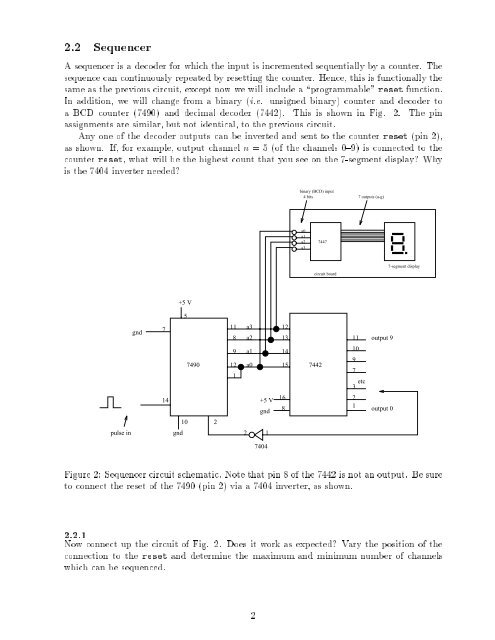
2.2 SequencerA sequencer is a decoder for which the input is incremented sequentially by a counter. Thesequence can continuously repeated by resetting the counter. Hence, this is functionally thesame as the previous circuit, except now we will include a \programmable" reset function.In addition, we will change from a binary (i.e. unsigned binary) counter <strong>and</strong> decoder toa BCD counter (7490) <strong>and</strong> decimal decoder (7442). This is shown in Fig. 2. The pinassignments are similar, but not identical, to the previous circuit.Any one of the decoder outputs can be inverted <strong>and</strong> sent to the counter reset (pin 2),as shown. If, for example, output channel n = 5 (of the channels 0{9) is connected to thecounter reset, what will be the highest count that you see on the 7-segment display? Whyis the 7404 inverter needed?binary (BCD) input4 bits 7 outputs (a-g)a0a1a2a37447circuit board7-segment display+5 V5gnd7118a3a2121311 output 99 a1 147490 12 a0 15 74421109714+5 Vgnd1683 etc 21output 0102pulse ingnd217404Figure 2: Sequencer circuit schematic. Note that pin 8 of the 7442 is not an output. Be sureto connect the reset of the 7490 (pin 2) via a 7404 inverter, as shown.2.<strong>2.1</strong>Now connect up the circuit of Fig. 2. Does it work as expected? Vary the position of theconnection to the reset <strong>and</strong> determine the maximum <strong>and</strong> minimum number of channelswhich can be sequenced.2