'UDLQDJH DQG 6HZDJH À :DVWH :DWHU &ROOHFWLRQ; ... - WILO
'UDLQDJH DQG 6HZDJH À :DVWH :DWHU &ROOHFWLRQ; ... - WILO
'UDLQDJH DQG 6HZDJH À :DVWH :DWHU &ROOHFWLRQ; ... - WILO

You also want an ePaper? Increase the reach of your titles
YUMPU automatically turns print PDFs into web optimized ePapers that Google loves.
Programme overview and fields of applicationsMain field of application• – • • – – – – – – – – – – – •– – • • – – – – – – – – – – – •• – • • – • • 1 ) • • – • – – – – •– – • • – • – – – – – – – – – •• – • • – – – – – – – – – – – –– – – – – • – – – – • – – – – –– – – – – – • 1 ) – – – – – – – – –– – – – – • – – – – – – – – – –– – – – – • • 1 ) – – – – – – – – –• – – – • • – • • • • • – – – •– – – – – • – • • • – – – – • •– – – – – – – – • – • – – – – •– – – – – – – – – – – – • – – –– – – – – – – – – – – – • – – –– – – – – – – – – – – – • – – –– – – – – – – – – – – – • – – –– – – – – – – – – – – – – – • •– – – – – • – – – – • – – – • –– – – – – – – – • – • • • • • •– – – – – – – – • – • • • • • •– – – – – – – – • – • • – • • –– – – – – – – – – – – • – • – –– – – – – – – – – – – • – • – –– – – – – – – – • – • • – • • –– – – – – – – – – – – – – • – –Pumpen mit axial geteiltemGehäuseTrockenläuferpumpenBlockpumpenNormpumpenFields of application:Raw water intakeDesalinationProfessional irrigation/agricultureEnergy/Leisure/ServiceSpecial applicationsMehrstufige Hochdruck-KreiselpumpenWastewater collection and transportWastewater treatmentDewatering (incl. Flood Control)Industrial processWilo-Katalog Water Management – 50 Hz – Wasserversorgung – Wasserversorgung / Heizung, Klima, Kälte – Ausgabe 2011/2012 – Änderungen vorbehalten5
ContentsGeneral notes and abbreviations 6Planning guide 8Waste water collection 21Lifting unitsPumps stationsSolids separation systemsWaste water collectionWaste water transport 93Submersible sewage pumps with maceratorSubmersible sewage pumpsWaste water transportElectrical accessories 135Recommended accessoriesEquipment/functionProduct descriptionsElectrical accessoriesSchalt- und RegelgerätePumpenmanagementWilo Water Management catalogue – 50 Hz – Drainage and Sewage – Waste water collection and transport – Edition 2012/2013 – Subject to change without prior notice3
Drainage and Sewage - Waste Water Collection and TransportContentsWaste water collectionLifting units Series overview 21Wilo-DrainLift S 25 *)Wilo-DrainLift M 27 *)Wilo-DrainLift L 29 *)Wilo-DrainLift XL 31 *)Wilo-DrainLift XXL 33 *)Wilo-DrainLift FTS 35Pumps stations Series overview 42Wilo-DrainLift WS 40 Basic 45Wilo-DrainLift WS 40-50 52Wilo-DrainLift WS 625 61Wilo-DrainLift WS 830 67Wilo-DrainLift WS 900 / 1100 72Solids separation systems Series overview 77Wilo-EMUport FTS MS 81Wilo-EMUport FTS MG 84Wilo-EMUport FTS FS 87Wilo-EMUport FTS FG 90*) see Wilo online catalogue4 Wilo Water Management catalogue – 50 Hz – Drainage and Sewage – Waste water collection and transport – Edition 2012/2013 – Subject to change without prior notice
Drainage and Sewage - Waste Water Collection and TransportContentsWaste water transportSubmersible sewage pumps with macerator Series overview 93Wilo-Drain MTC 95Wilo-Drain MTS 109Submersible sewage pumps Series overview 118Wilo-Drain TM/TMR/TMW 123 *)Wilo-Drain TC 40 125 *)Wilo-Drain STS 40 127 *)Wilo-Drain STS 65 129 *)Wilo-Drain TP 50 131 *)Wilo-Drain TP 65 131 *)Wilo-Drain TP 80 133 *)Wilo-Drain TP 100 133 *)Electrical accessoriesWaste water collectionWaste water transportRecommended accessories 135Equipment/function 137Product descriptions 140*) see Wilo online catalogueElectrical accessoriesSchalt- und RegelgerätePumpenmanagementElectrical accessoriesWilo Water Management catalogue – 50 Hz – Drainage and Sewage – Waste water collection and transport – Edition 2012/2013 – Subject to change without prior notice5
General notes and abbreviationsAbbreviationMeaning1~ 1-phase current3~ 3-phase current-A Float switch attachedDDIDiDi min.Direct activationLeakage detectionInside diameterMinimum inside diameterDM Three-phase motor, 3~DNEBMNominal diameter of the flange connectionIndividual run signalEM Single-phase motor, 1~ESMGRD/GLRDFIndividual fault signalMechanical sealH, Hman Delivery headThrust in newtons (N) (for submersible mixers)H ASuction head; inlet floor to ground levelH BInstallation depth to inlet floorH NSite altitude above MSL (mean sea level)H GGroundwater level to MSL (mean sea level)I AStarting currentI N Nominal current; current at P 2Inst. Installation: H = horizontal, V = verticalP 1P 1.1P 2 (P N )PNPTCPT 100Q (=)Supply availability (L = stock article, C = available in2 weeks, K = available in 4 weeks, A = available on request)Power consumption (power supplied from the network)Power consumption at the duty pointNominal motor powerPressure class in bar (e.g. PN10 = suitable up to 10 bar)Positive temperature coefficient (PTC thermistor sensor)Platinum temperature sensor with a resistance value of100 at 0 °CVolume flow-S Float switch attachedSBMSSMWSKY/Run signal or collective run signalFault signal or collective fault signalThermal winding contacts (in motor for monitoring thewinding temperature, full motor protection throughadditional tripping unit)Star-delta switchingOperating mode of double pumps: Individual operationof the respective duty pumpOperating mode of double pumps: Parallel operation ofboth pumpsNumber of poles of electric motors:2-pole motor = approx. 2900 rpm at 50 HzNumber of poles of electric motors:4-pole motor = approx. 1450 rpm at 50 HzNumber of poles of electric motors:6-pole motor = approx. 950 rpm at 50 HzMaterial Meaning AISI1.0570 Steel S355J2G3 A1061.4021 Chromium steel X20Cr13 4201.4057 Chromium steel X17CrNi16-2 4311.4112 Chromium steel X90CrMoV18 440B1.4122 Chromium steel X39CrMo17-11.4301 Chromium-nickel steel X5CrNi18-10 3041.4305 Chromium-nickel steel X8CrNiS18-9 3031.4306 Chromium-nickel steel X2CrNi19-11 304L1.4308 Chromium-nickel steel GX5CrNi19-101.44011.44041.44081.44601.44621.44701.4517Chromium-nickel-molybdenum steelX5CrNiMo17-12-2Chromium-nickel-molybdenum steelX2CrNiMo17-12-2Chromium-nickel-molybdenum steelGX5CrNiMo19-11-2Chromium-nickel-molybdenum steelX3CrNiMo 27-5-2Chromium-nickel-molybdenum steelX2CrNiMoN22-5-3Chromium-nickel-molybdenum steelGX2CrNiMoN22-5-3304CF8316316L316329329(2205)329Chromium-nickel-molybdenum steel withcopper addition GX2CrNiMoCuN25-6-3-3 3291.4528 Blade steel X105CrCoMo1821.45411.45421.45711.4581AbrasiteAlAl-oxideCCeramCompositeCrEN-GJLEN-GJL 200EN-GJL 250Chromium-nickel steel with titanium additionX6CrNiTi18-10Chromium-nickel steel with copper andniobium additions X5CrNiCuNb16-4Chromium-nickel steel with titanium additionX6CrNiMoTi17-12-2Chromium-nickel-molybdenum steel withniobium addition GX5CrNiMoNb19-11-2Chilled cast iron material for use in stronglyabrasive fluidsLight metal material (aluminium)Aluminium oxideCarbonCoating with very high adhesive strengthfor long-lasting corrosion protectionHigh-strength plastic materialChromiumCast iron with lamellar graphite, also referredto as grey cast iron. The use of greycast iron in domestic water systems isgoverned by the Drinking Water Directive98/83/EC and applicable recognised technicalrules and standards!Grey cast iron GG20Grey cast iron GG25440B+Co321630316Ti316 /316Nb6 Wilo Water Management catalogue – 50 Hz – Drainage and Sewage – Waste water collection and transport – Edition 2012/2013 – Subject to change without prior notice
General notes and abbreviationsMaterial Meaning AISIEN-GJSEN-GJS-500-7G-Al Si12GfKGGGGGInoxABSPA 30GFPE-HDPP-GF30PURSiCStSt.vz.Cast iron with spheroidal graphite, also referredto as spheroidal cast iron. The useof spheroidal cast iron in domestic watersystems is governed by the Drinking WaterDirective 98/83/EC and applicable recognisedtechnical rules and standards!Spheroidal cast iron GGG50Die-cast aluminiumFibreglass plasticSee EN-GJLSee EN-GJSStainless steelAcrylic butadiene styreneSee CompositeHigh-density polyethylenePolypropylene, reinforced with 30% fibreglassPolyurethaneSilicon carbideSteelGalvanised steelV2A Material group, e.g. 1.4301, 1.4306 304V4A Material group, e.g. 1.4404, 1.4571 316Wear and tearPumps or parts of pumps are subject to wear in accordance with thestate-of-the-art (DIN 31051/DIN EN 13306). This wear may vary dependingon operating parameters (temperature, pressure, speed, waterconditions) and the installation/usage situation and may result inthe malfunction or failure at different times of the aforementionedproducts/components, including their electrical/electronic circuitry.Wearing parts are all components subject to rotary or dynamic stress,including electronic components under tension, in particular:• Seals (including mechanical seals), seal rings• Stuffing box• Bearings and shafts• Impellers and pump components• Wear rings and counter rings• Stationary wear rings/wear plates• Macerator• Capacitors• Relays/contactors/switches• Electronic circuits, semiconductor components, etc.Pumps and continuous-flow machines (like submersible mixers andrecirculation pumps), as well as their coated components (cataphoretic,2K or Ceram coating) are subject to constant wear due tothe abrasive fluid contents. For this reason the coating is also countedas a wearing part of these units!We do not accept any liability for faults or defects arising from naturalwear and tear.Wilo – General Terms of Delivery and ServiceThe latest version of our General Terms of Delivery and Service can befound on the Internet atwww.wilo.comWilo Water Management catalogue – 50 Hz – Drainage and Sewage – Waste water collection and transport – Edition 2012/2013 – Subject to change without prior notice7
Planning guideBasic hydraulic principlesVibrations and resonanceWhen sewage pumps are installed and connected, various aspectsmust be observed to guarantee smooth operation. Fundamentally,every moving machine part causes vibrations.In the case of submersible motor pumps and monobloc pumps, duringrotation, free centrifugal forces are generated at the circulationfrequency. Also, the hydraulic forces acting on the pump impellerconsiderably contribute to the machine vibrations.In order to avoid malfunctions and damage, the strength of the vibrationsin the operating state may not exceed a certain threshold. Thisis achieved by statically and dynamically balancing the correspondingparts.If the pumps are subject to additional external vibrations due to unfavourableinstallation and connections, these vibrations are superimposed.These vibrations can put high levels of stress on individualcomponents.In order for the pumps to work without disturbances and to have longservice lives, they must be installed according to the generally validrules of technology.General notes• The volume flow to be handled by the pump must exceed the volumeflow of approaching sewage. Make sure that the pumps run as closeto the optimum duty point as possible to ensure durability and optimumperformance.• Consider a loss in performance with increasing pump age. The volumeflow and pressures can be negatively influenced by abrasion and corrosion.• Design the pump so that it operates as efficiently as possible.• Steep pump curves prevent clogging in the pressure pipe, since whenthere's increased backpressure, the pump also increases pressurealong its pump curve and rinses away the deposits.• When selecting accessories, take the material properties into considerationwith regard to the corrosion- and abrasion-resistance.• Compensate for peak inflows for economical and safety reasons byusing double-pump systems (pump splitting, standby pump is alwaysto be considered separately).• If the transfer point (drainage pipe) lies underneath the sump level,ventilation should be provided, since otherwise the created suctioncould empty the complete sump, incl. the pump. This would result inventilation difficulties and should therefore be checked in advance.• Observe the various operating conditions for pipes which are not permanentlyinstalled in one place. The partial and full-filling situationsshould be observed.Pipe and pump materialWhen designing, observe that the following influences could meanadditional requirements for your system:• Flow velocity of the fluid > Noises, wear• pH value of the fluid > Material damage, corrosion• Chemical constituents of the fluid > Corrosion• Atmospheric conditions, such as humidity, salt content in the air, etc.> Corrosion• Outside and fluid temperature > Fluid aggressiveness, corrosion• Dwell time of the fluid in the pipe > Odour development• Leakage currents due to using materials having different electronnegativityDue to the material changes and the resulting pressure level change,pipes for underground use should be designed as PN 10 pipes.Wilo Water Management catalogue – 50 Hz – Drainage and Sewage – Waste water collection and transport – Edition 2012/2013 – Subject to change without prior notice9
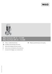
Planning guidePressure lossesPressure loss in hoses1000,1 1 10 100 200Q [m³/h]100Dv[m]Dv[m]10ø25mm / 1“ø32mm / 1¼“ø38mm / 1½“ø50mm / 2“ø52mm / C-Schlauchø63mm / 2½“ø75mm / B-Schlauchø102mm / 4“ / A-Schlauchø127mm / 5“ø152mm / 6“10110,10,10,11 10 100 200Q [m³/h]Q = volume flow; Dv = pressure loss per 100 m hose (k b = 0.25)10 Wilo Water Management catalogue – 50 Hz – Drainage and Sewage – Waste water collection and transport – Edition 2012/2013 – Subject to change without prior notice
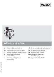
Planning guidePressure lossesPressure loss in fixed pipes0,4 1,0 2,0 4,0 10 20 40 100 200 400 1000 [m³/h] 600030,0[m]20,0DN2030,0[m]20,0DN2510,0DN32DN4010,04,0 m/s8,06,0DN508,06,03,0 m/sDN654,0DN804,0DN100DN1252,0 m/s2,0DN1502,01,5 m/sDN2001,0DN2501,00,80,61,0 m/sDN300DN350DN4000,80,60,8 m/sDN5000,4DN6000,40,6 m/sDN700DN8000,20,4 m/sDN900DN10000,20,10,10,1 0,2 0,4 1,0 2,0 4,0 10 20 40 100 200 400 [l/s] 1000 2000Q = volume flow; Dv = pressure loss per 100 m hose (k b = 0.1)Wilo Water Management catalogue – 50 Hz – Drainage and Sewage – Waste water collection and transport – Edition 2012/2013 – Subject to change without prior notice11
Planning guidePressure lossesFactors for adapting to other materials/older linesk bPipe type0,1 new galvanized steel pipes0,8 newly rolled steel pipes, new plastic pipes1,0 new cast-iron pipes, bitumen coated cast-iron pipes1,25 older surface corroded cast-iron pipes1,5 newly galvanised steel pipes, cleaned cast-iron pipes1,7 encrusted pipes2,0 new concrete pipes, medium-gloss2,5 stoneware pipes3 new concrete pipes, flat line markings15-30 cast-iron pipes with light to heavy encrustationsLosses in valves and pipe line contentsValve type Unit Nominal diameterDN 40, 1¼ DN 32, 1½ DN 50, 2 DN 65, 2½ DN 80, 3 DN 100 DN 150Non-return valve K V m 3 /h – – 158 267 405 632 1423Non-return ball valve with flange K V m 3 /h – – 87 136.5 267 396 890Non-return ball valve with female thread K V m 3 /h 26 54 70 115 180 – –Gate valve K V m 3 /h – – 160 280 470 830 2000Pipe contents l/m 0.8 1.3 2.1 2.9 4.3 8.2 17Formula for calculating the losses in valvesΔ PV = [m³/h] ²( K V [m³/h] ) = Volume flow at dutypointK V = Flow coefficient from tableExampleNon-return ball valves with flange, DN 80,dutypoint 40 m 3 /hΔ PV =( )40 2= 0.022 bar = 0.22 m26712 Wilo Water Management catalogue – 50 Hz – Drainage and Sewage – Waste water collection and transport – Edition 2012/2013 – Subject to change without prior notice
Planning guideBasic electric principlesStarting currentThis is the current which is required during the start-up operation ofa machine to overcome friction losses and starting torques. Thestarting current can be up to seven times that of the nominal current,depending on the type of start-up. When there is instability in theelectric mains or for larger motors, corresponding devices must beprovided to reduce the starting current. These could be soft starters,frequency converters, etc. Designing the motor as a star-delta motorcan already reduce the starting current.Operating modes (in acc. with DIN EN 60034-1)See “Operating modes” chapterIndividual run signalIndicates the fault of the individual pump and demonstrates an exactevaluation method for building control systems.Motor protectionFor a safe operation of a motor, this must be protected against unacceptablehigh warming. Such an unacceptable warming can resultfrom faults which increase the motor current and strongly heat upthe motor:• Overload• Phase failure• Undervoltage• BlockingThese faults can be recognised by an overload relay or a motor protectionswitch which then switch off the motor. Overload relays andmotor protection switches may only be set to the maximum nominalcurrent of the motor.First digitOverload relayPrinciple of operation:The thermal protection is ensured by bimetals which heat up as themotor current flows via heating windings. For every conductive lineto the motor, a separate bimetal with corresponding heating windingis provided. If the power consumption of just one motor winding exceedsthe predefined value over several seconds, the generated heatwill deform the bimetal which then triggers the latch and switches offthe motor contactor. Also, if a phase fails (irregular heating of the bimetalstrips), the motor is switched off after a short period of time.After a thermal triggering has taken place, the switch can only beswitched on again after the bimetals have cooled down sufficiently.Overload relays don't switch off the motor directly, they have a contactfor relatively low switching frequencies. This contact activates acontactor which then switches the motor off in the event of a fault. Incontrast to the motor protection switch, an overload relay does nothave a short-circuit trip. This is why safety fuses should be installedin the supply line for one or several motors which are protected byoverload relays. Moreover, the reactivation of overload relays can bedone manually or automatically. The reactivation should be donemanually in order to avoid a permanent switching on and off whenthere is a fault.Motor protection switchWith motor protection switches, motors can be switched on and offunder normal operating conditions. The thermal triggering is basedon the principle of the overload relay. However, the operator is in aposition to switch off the motor during operation or in the event offault. Moreover, most motor protection switches have an additionalmagnetic quick triggering which protects the downstream line andthe motor against short circuits. With lower currents, these switchesare short-circuit proof, i.e. a back-up fuse may not be required.Other faults which lead up to an increased heating-up:• Dry-running of motors that may only operate in a submerged state• Unacceptable high fluid temperatures / ambient temperature• Unacceptable running times in short-term operationThese faults do not influence the current consumption of the motorand can therefore not be recognised by the upstream overload protection!For such faults, temperature sensors are used which are directlyimbedded in the component to be protected (motor winding).Protection measures (DIN VDE 0100-410)Protection classes:(DIN EN 50529 / VDE 0470 Part 1)The type of protection which a housing offers to e.g. protect againstdirect contact, is defined by the IP (International Protection) codes.This is made up of the “IP” and two digits (e.g. IP 54).First digit:• Protection of people against contact with dangerous parts• Protection of the equipment against ingress of solid foreign matterSecond digit:• Protection of the equipment against the ingress of waterSecond digitIndex Protection against contact Protection against foreign matter Protecton against water0 No protection No protection No protection1 Protection against contact with the backof the hand2Protection against touching with fingers3Protection against touching with toolsProtection against solid foreign matter50 mm diameterProtection against solid foreign matter12.5 mm diameterProtection against solid foreign matter2.5 mm diameterProtection against vertically drippingwaterProtection against dripping water fallingat a tilted angle (15°)Protection against spraying water fallingat a tilted angle of up to 60°4Protection against solid foreign matter Protection against splashing water fromProtection against touching with a wire1.0 mm diameterall directions5 Protection against touching with a wire Dustprotected Protection against water jets6 Protection against touching with a wire Dustproof Protection against strong water jets78– –– –Protection against temporary submersionin the waterProtection against permanent submersionin the waterWilo Water Management catalogue – 50 Hz – Drainage and Sewage – Waste water collection and transport – Edition 2012/2013 – Subject to change without prior notice13
Planning guideOperating modesThe operating mode defines the permissible motor activation period.Fundamentally, it is to be made sure that the installed temperaturemonitor of the motors is correctly connected. This ensures that thetemperature classes of the windings are complied with if the operatingtime is exceeded or incorrect operating mode is used.S1 permanent operationDefinition:Operation at a constant load which is maintained until the machine isable to reach the thermal steady state.The machine is designed such that the cooling under nominal conditionsis sufficient. The operating mode provides no information aboutwhether the machine is to be operated wet or dry, however. If no operatingmode is specified on the rating plate of a machine, S1 permanentoperation applies.S2 short-term operationDefinition:Operation at a constant load, the duration of which is not sufficientto reach the thermal steady state, and a following time at a standstill,in which the machine temperatures, which have dropped again, onlydeviate from the coolant temperature by less than 2K.The power dissipation of the machine is greater than that which canbe conducted away via the coolant. For S2, the permissible operatingtime is always specified (e.g. S2 15 min). After this operating time,the machine must cool back down to the ambient temperature. Thisoperating mode is mainly used with dry set-up machines.PPtP VtP VttΘΘ maxΘΘ maxP = loadΔt PtP = loadP V = electrical losses = temperature max = max. temperaturet = timeT C = cycle durationt p = operating time at constant loadt R = standstill time with no current in windings,relative activation period = t P /T CtP V = electrical losses = temperature max = max. temperaturet = timeT C = cycle durationt p = operating time at constant loadt R = standstill time with no current in windings,relative activation period = t P /T C14 Wilo Water Management catalogue – 50 Hz – Drainage and Sewage – Waste water collection and transport – Edition 2012/2013 – Subject to change without prior notice
Planning guideOperating modesS3 intermittent operation without influence on the startingcurrentDefinition:Operation which is composed of a sequence of identical cycles, ofwhich each one involves an operating time with a constant load and astandstill time, whereby the starting current has no noticeable effecton the excess temperature.The power dissipation of the machine is greater than that which canbe conducted away via the coolant. With operating mode S3, the cycleduration is specified in percent and the cycle time is also specified.Example for S3 25% 10 min: The activation period is 2.5 min and thepause is 7.5 min. If no cycle duration is specified, a cycle duration of10 min. is assumed.PT CΔt PΔt RtP VtΘΘ maxP = loadP V = electrical losses = temperature max = max. temperaturet = timeT C = cycle durationt p = operating time at constant loadt R = standstill time with no current in windings,relative activation period = t P /T CtWilo Water Management catalogue – 50 Hz – Drainage and Sewage – Waste water collection and transport – Edition 2012/2013 – Subject to change without prior notice15
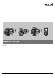
Planning guidePumps stationsGeneral information:• Backflow fittings and slide valves are to be generally placed high up inthe sump in the pressure pipe since deposits are avoided this way andthe fittings are easily accessible for maintenance, cleaning and inspection.• Check valves are to be generally provided for maintenance and repairwork. These are sometimes required by the standards.• Pressure pipes are to be dimensioned according to the parametersspecified in the relevant standards, e.g. flow rates and pressure stage.• The pump sump is to be designed as small as possible around thepump.• If the outlet of the pressure pipe lies underneath the suction port ofthe pump, a ventilator, e.g. vacuum interrupter (accessory) is to beinstalled in the common pressure pipe to avoid the pump sump beingsucked out up to underneath the suction port.Double-pump pumps station1 Foot elbow2 Non-return valve3 Gate valve4 Y-piece (Y-pipe)5 Guide pipe6 Inlet7 Pressure outlet8 Cable conduit9 Ventilation pipe958Determining the volume flowThe accumulated domestic sewage volumes are calculated roughlyaccording to the water consumption of the community in question.They depend on the number of residents “E” as well as the wastewateroutflow “a” in litres [l] per resident and day (l/ET, according to experienceapprox. 120 l/ET). Under the condition that the maximumhourly outflow Q max is one fourteenth of the average daily outflow,the following results:7 4Q max in [l/s]= (E x a)/(14x60x60)326When dimensioning the pressure pipe, make sure that the minimumflow rate of 0.7 m/s is maintained. To take the rainwater and groundwater into account, which accumulates on the sewage side evenwhen the drainage system is separated, the calculated value is to beincreased by 50 - 130 % Further information about this can be foundin the planning guide “Sewage technology” (can be ordered).918Determining the size of the usable suction space of sewage pumpingstationsThe usable impoundment volume of the suction space depends onthe permissible switching frequency and the volume flow of the largestpump installed. With two identical pumps and automatically alternatingactivation, the volume can be cut in half.The permissible switching frequency “S” for each pump is not to beexceeded (depends on the selected pump type. See “Equipment/function”).For higher motor power ratings or switching frequencies, please consultWilo.The volumes indicated in the diagram are minimum values required toensure smooth pumping operation under unfavourable conditions.This is the case when the inflow for a pump is half of the volume flow.This results in a maximum number of activation operations per hour.746For Wilo synthetic sumps WS 40-50, 625, 900, 1100 the useable impoundmentvolume is defined as follows, depending on the selectedpump type:• At the inlet of the sump, strong surge currents on the pump andcomponents of the level sensors are to be avoided.WS 40-50 55 - 160 LWS 625 95 - 150 LWS 900 110 - 150 LWS 1100 200 - 280 L• During the building phase, a foundation or earthing strip is to be providedfor potential equalisation.16 Wilo Water Management catalogue – 50 Hz – Drainage and Sewage – Waste water collection and transport – Edition 2012/2013 – Subject to change without prior notice
Planning guidePumps stationsVolume flow20 50 100 200 300 500 1000 2000 3000 5000 Q[Ugpm]V[m³]20 50 100 200 300 500 1000 2000 3000 5000 Q[Igpm]V[m³]5040305040302010S=1S=2S=3S=4S=5S=6S=8S=10S=12S=15S=2020105544332211 2 3 4 5 10 20 30 40 50 100 200 300 400 500 Q[l/s]15 10 20 30 40 50 100 200 300 500 1000 2000 Q[m³/h]Wilo Water Management catalogue – 50 Hz – Drainage and Sewage – Waste water collection and transport – Edition 2012/2013 – Subject to change without prior notice17
Planning guideSolids separation systemsRequirementThe amount of solids in domestic sewage is continuously increasingdue to current water savings. This means that the pumps in pumpingstations need even larger free ball passages, which also means an increasein pump power consumption.FunctionWith the solids separation system, the inflowing sewage flows intothe distribution tank and from there into the open solids separationtank. The solids are kept back here. Only prepurified sewage is nowable to pass through the pump into the large, combined collectionreservoir.While the collection reservoir is filled, the water level in the solidsseparation tank rises. The shut-off ball automatically closes the inlet.Now, pumping starts when the correct level has been reached. Thepump pumps in the reverse direction. The sewage flows through thesolids separation reservoir and thus conveys the “filtered-out“ solidsinto the outgoing pressure pipe.Then, the entire solids separation system is flushed and cleaned.Pumping is stopped again, when the correct level has been reached.The shut-off ball drops, leaving the path free for a new filling sequence.During this pumping sequence, the sewage is pumped intothe other solids separation reservoir.Advantages of the solids separation system• Uses pumps with free ball passage < 80 mm, thus reducing fuel requirementsand operating costs while increasing efficiency• Hygienic conditions for maintenance and assembly work• Pump room is clean, dry, and odourless• Less wear, since the solids are not pumped by the hydraulic unit• Submersible sewage pump with adjusted impeller and protectionclass IP 68 (submersible)• No corrosion problems, no effect from the formation of hydrogensulphide871264531 = inlet pipe, 2 = manifold, 3 = solids collection reservoir , 4 = solids separation flap, 5 = collection reservoir with filtered sewage, 6 = shut-off ball, 7 = dischargepipeline, 8 = ventilation and exhaust18 Wilo Water Management catalogue – 50 Hz – Drainage and Sewage – Waste water collection and transport – Edition 2012/2013 – Subject to change without prior notice
Planning guideInquiry data sheet for Wilo-EMUport FTS productsCustomer dataData for installation in a building or structureCompany: ___________________ Suction head (H A ): ___________________mName: ___________________ Existing installation space: ___________________mmProject name: ___________________ Building/structure floor space: __________________mDeadline: ___________________ Installation opening: ___________________mxmGeneral informationData for PE-HD pump sumpType of construction: o Newbuild Site altitude above MSL (H N ) or 0,00: ___________________mo Reconstruction Desired diameter: ___________________mmPumping station: o Wet well installation Installation depth to inlet floor (H B ): ___________________mo Dry well installation Ground water level (H G ): ___________________mo Solids separation systemTraffic load in accordance with DIN ENSolids separation system: o in building or structure o Class A / o Class B / o Class Do in PE-HD sumpType of fluid: o Rainwater Equipmento Sewage o Switchgear o Residual-current-operated protectionswitchBasic data o Frequency converter o Soft starterInlet amount ___________________l/s o Display for o Pump(s) operationFlow rate per pump*: ___________________l/s o Operating hoursDelivery head per pump ___________________m o Tank filling levelNumber of pumps: ___________________ o Pump(s) fault(s)Number of pumps on standby ___________________ o Fault, floodingInlet pipe: o Data transmission o CableDiameter (DN): ___________________ o GSM / UMTS moduleMaterial: ___________________ o Level control device o PneumaticWith gate valve: o Yes/ o No o Hydrostatic/capacitivePressure pipe o Sump lighting o FanDiameter (DN): ___________________ o Volume flow rate meter o CompactDrawing available: o Yes/ o No o With external displayo Outdoor cabinet for switchgearo Prepared for electricity metero Emergency power connection* = in relation to the minimum flow velocity > 0.7 m/s (e.g., DN 100 (110 x 6.6 mm): min. 5.2 l/s)Wilo Water Management catalogue – 50 Hz – Drainage and Sewage – Waste water collection and transport – Edition 2012/2013 – Subject to change without prior notice19
Planning guideInquiry data sheet for Wilo-EMUport FTS productsInstallation drawing Wilo-EMUport FTS...HNHA HBHGKey:H A = specification for solids separation system in version for building installation (Wilo-EMUport FTS MG…/FG…)H B = specification for solids separation system with PE-HD sump (Wilo-EMUport FTS MS…/FS…)H G = groundwater level of site ground surfaceH N = site altitude over MSLYour contact partner for solids separation systemsMr Carsten KrusePlanning/CalculationT: +49 571 50550-57F: +49 571 50550-79E: carsten.kruse@wilo.comLanguages: German/EnglishMr Karl BargPlanning/CalculationT: +49 571 50550-71F: +49 571 50550-79E: karl.barg@wilo.comLanguages: German/EnglishMr Hartmut BarkeyProduct managerT: +49 571 50550-75F: +49 571 50550-79E: hartmut.barkey@wilo.comLanguages: German/English20 Wilo Water Management catalogue – 50 Hz – Drainage and Sewage – Waste water collection and transport – Edition 2012/2013 – Subject to change without prior notice
Waste water collectionLifting unitsSeries overviewSeries Wilo-DrainLift S Wilo-DrainLift MProduct photoWaste water collectionDuty chartH[m]5,0Wilo-DrainLift S4,03,0S 1/52,01,000 4 8 12 16 20 24 Q[m³/h]H[m]8765432100 5 10 15 20 25 30Wilo-DrainLift MM 1/8M 2/8Q[m³/h]Design Compact sewage lifting unit with integrated pump Sewage lifting unit with 1 or 2 integrated pumpsApplicationMax. intake/hwith S3 operationVSpecial features/product advantagesFurtherinformation• For the pumping of raw sewage that cannot be piped to thesewer system through the use of natural inclines.• Drainage of individual roomsmax. 600 l• Easy to install due to:- Low weight- Large scope of delivery- Including non-return valve• Flexible due to:- Freely selectable inlets- Front-wall-like installation- Space-saving installation (depth 30 cm)• Safe due to:- Reliable pneumatic level measurementSeries information from page 25Wilo online catalogue at www.wilo.com• Pumping of untreated sewage that cannot be conveyed tothe sewer system via natural slope.• For drainage of single-family houses and small buildingcomplexes.max. 1080 ... 3600 l• Easy to install due to:- Compact dimensions- Low weight- Large scope of delivery• Flexible due to:- Freely selectable inlets• Safe due to:- Integrated mains-independent alarm function- Integrated thermal motor protection- Additional potential-free contact- Maintenance interval display for M2- Early fault detection for M2Series information from page 27Wilo online catalogue at www.wilo.comWilo Water Management catalogue – 50 Hz – Drainage and Sewage – Waste water collection and transport – Edition 2012/2013 – Subject to change without prior notice21
Waste water collectionLifting unitsSeries overviewSeries Wilo-DrainLift L Wilo-DrainLift XLProduct photoDuty chart0H[m]201612840 5 10 15 20 25 30 35Wilo-DrainLift LL.../25L.../20L.../15L.../10Q[m³/h]0H[m]20161284Wilo-DrainLift XLXL 2/25XL 2/20XL 2/15XL 2/100 5 10 15 20 25 30 35 Q[m³/h]Design Sewage lifting unit with 1 or 2 integrated pumps Sewage lifting unit with 2 integrated pumpsApplicationMax. intake/hwith S3 operationVSpecial features/product advantagesFurtherinformation• For the pumping of raw sewage that cannot be piped to thesewer system through the use of natural inclines.• For drainage of multi-family houses and smaller structures(cafés, etc).max. 1050 ... 3000 l• Easy to install due to:- Low weight- Only one pressure outlet with double-pump system (integratedY-pipe)- Built-in non-return valve- Large scope of delivery• Flexible due to:- Freely selectable inlets- Wide performance range• Safe due to:- Large tank volume- Mains-independent alarm function- Additional potential-free contact- Comfort version "C" with individual fault signalSeries information from page 29Wilo online catalogue at www.wilo.com• For the pumping of raw sewage that cannot be piped to thesewer system through the use of natural inclines.• For drainage of larger structures (restaurants, departmentstores, etc.)max. 15600 l• Easy installation / commissioning due to- Built-in non-return valve- Higher flexibility in the intake area (connection is heightadjustableand can be swivelled)- Menu-prompted setting on switchgear• Safe due to:- Large switching volume- Additional potential-free contact- Reliable level measurement due to level sensor- Suitable for permanent operation (due to integratedsheath current cooling)Series information from page 31Wilo online catalogue at www.wilo.com22 Wilo Water Management catalogue – 50 Hz – Drainage and Sewage – Waste water collection and transport – Edition 2012/2013 – Subject to change without prior notice
Waste water collectionLifting unitsSeries overviewSeries Wilo-DrainLift XXL Wilo-DrainLift FTSProduct photoWaste water collectionDuty chartH[m]Wilo-DrainLift XXL201816141210XXL 10..-2/8,48XXL 10..-2/7,064XXL 8..-2/2,1 XXL 10..-2/5,22XXL 8..-2/1,7XXL 10..-2/3,900 20 40 60 80 100 120 Q[m³/h]H[m]Wilo-DrainLift FTS28242016128400 10 20 30 40 50 60 Q[m³/h]Design Sewage lifting unit with 2 dry-mounted pumps Sewage lifting unit with solids separation systemApplicationMax. intake/hwith S3 operationVSpecial features/product advantagesFurtherinformation• For the removal of untreated sewage that cannot be pipedto the sewer system through the use of natural inclines.• For drainage of large building complexes (hotels, hospitals,etc.).max. 26400 ... 55200 l –• Large tank volume• Low weight of individual components• Wide performance range• Suitable for permanent operation (due to integrated sheathcurrent cooling)Series information from page 33Wilo online catalogue at www.wilo.com• For the pumping of raw sewage that cannot be piped to thesewer system through the use of natural inclines.• For drainage of large building complexes (hotels, hospitals,etc.).• High efficiency, due to pumps with small free ball passage• Large delivery heads• System non-susceptible to clogging, due to solids separation• Large tank volumeSeries information from page 35Wilo online catalogue at www.wilo.comWilo Water Management catalogue – 50 Hz – Drainage and Sewage – Waste water collection and transport – Edition 2012/2013 – Subject to change without prior notice23
Waste water collectionLifting unitsEquipment/functionDesignWilo-DrainLift ...S M L XL XXL FTSSubmersible • • • • • •Single-pump system • • • - - -Double-pump system – • • • • •Single-phase AC motor • • – – – –Three-phase motor • • • • • •Pump position: motor components outside the tank • • • • – –Pump position: outside the tank – – – – • •Pump position: in tank – – – – – –Sealing chamber • • • • • •Sealing for mechanical seal on fluid side • • • • • •Sealing for rotary shaft seal on fluid side – – – – – –Integrated non-return valve • • • • – •Sheath current cooling – – – • • •Single-channel impeller – – – – • •Multi-channel impeller – – – – – –Vortex impeller • • • • – •Macerator – – – – – –Equipment/functionInlet position freely selectable • • • • – –Active carbon filter – – – – – –Level control: with float switch – • • – – –Level control: with level sensor – – – • • •Level control: with pneumatic pressure transducer • – – – – –Motor temperature monitoring – – • – – –Mains-independent alarm – • • – – –Alarm for potential-free contact • • • • • •Ready-to-plug • • • • – –Connecting cable detachable • • • • • •Switchgear – • • • • •Hose connection for diaphragm hand pump • – • • • –Seal for suction pipe connection for diaphragm handpump– • – – – –Hose connection for ventilation • • • • • –Pressure hose – – – – – –Installation sundriesKit for pressure pipe connection – • • • • –Keyhole saw for inlet borehole • • • • – –Inlet seal • • • • – –Soundproofing material • • • – – –• = available, - = not available24 Wilo Water Management catalogue – 50 Hz – Drainage and Sewage – Waste water collection and transport – Edition 2012/2013 – Subject to change without prior notice
Waste water collectionLifting unitsSeries description Wilo-DrainLift SWaste water collectionDesignCompact sewage lifting unit with integrated pumpType keyExample: DrainLift S1/5 (1~)S1Single-pump system/5 Max. delivery head [m](1~) 1~: Single-phase version3~: Three-phase versionApplicationComplete sewage lifting unit ready for connection in accordance withDIN EN 12050-1.For the pumping of raw sewage that cannot be piped to the sewersystem through the use of natural inclines. Wilo-DrainLift S meetsthe requirements of DIN EN 12050-1 and DIN EN 12056. Minimumdimensions, combined with space-optimised installation area enablea wide range of different application options for:• Retrofitting installation of showers, toilets, saunas, etc.• Installation of toilets in basement flats• Expansion/renovation of flats and buildings• Innovative combination of different installation options for sewagelifting units in a single system, e.g.:- Direct toilet connection- Drainage of individual rooms- Front wall installation/recessed wall installationCan be used in the following installation types:As conventional sewage lifting unit for connection of a wall-mountedor stand-alone toilet or for complete room drainage. Due to compactdesign, system requires only minimum space.In conjunction with front wall installation/recessed wall installation,used as sewage lifting unit, integrated into commercially availablefront wall installation systems, in recessed wall installation as well asin pedestal profiles.Note:It must be possible to both install and remove the system after layingtiles. Observe installation instructions and accessories.Special features/product advantages• Easy to install due to:- Low weight- Large scope of delivery- Including non-return valve• Flexible due to:- Freely selectable inlets- Front-wall-like installation- Space-saving installation (depth 30 cm)• Safe due to:- Reliable pneumatic level measurementTechnical data• Mains connection 1~230 V, 50 Hz or 3~400 V, 50 Hz• Power consumption P 1 from 1.1 to 1.25 kW, depending on type• Cable length from system to switchgear/plug 4 m• Operating mode S3 - 15%• Fluid temperature max. 35 °C, for short periods up to 60 °C• Ambient temperature max. 40 °C• Free ball passage 40 mm• Pressure port DN 80• Inlet connection DN 40 / DN 100• Ventilation connection DN 70• Min. suction head (installation level to middle of inlet) 180 mm• Protection class (without switchgear) IP 67• Gross tank volume 45 lMaterials• Motor housing: stainless steel 1.4404 (AISI 316L)• Hydraulic housing: PE/PUR plastic• Impeller: PUR plastic• Tank: PE plasticEquipment/function• Ready-to-plug• Thermal motor monitoring• Level control with pneumatic pressure transducer• Potential-free contact• Pump cable detachable• Non-return valve• Inlet seal• Hole saw for inlet borehole• Hose connection for ventilation• Hose connection for diaphragm hand pump• Fixation material• Soundproofing materialWilo Water Management catalogue – 50 Hz – Drainage and Sewage – Waste water collection and transport – Edition 2012/2013 – Subject to change without prior notice25
Waste water collectionLifting unitsSeries description Wilo-DrainLift SDescription/designStainless steel motorProven construction in modern INOX & Composite design, includingefficiency-optimised vortex impeller.Carrying handle and fastening strapEasy handling, reliable standard-compliant installation and fixation(for buoyancy safeguards).Inlet DN 40For additional inlets from washbasins, bathtubs, etc.Freely selectable inletsOpen areas on both lengthways sides and on a facing side provide thewidest possible range of connection flexibility (see illustration). Observethe minimum suction head of the drainage fixtures.Installation beadingFor commercially available front-wall installation systems.Standard sound absorption strips or materialPrevent structure-borne noise transmission.TankLarge inspection opening. Inclined collection space for deposit-free,reliable operation. Connection possibility for a DN 70 ventilation pipeand for a diaphragm hand pumpScope of deliverySewage lifting unit ready for connection• Switchgear/plug• Non-return valve• Inlet seal DN 100• Keyhole saw• Fixation material• Soundproofing material• Installation and operating instructionsPump curves Wilo-DrainLift SH[m]Wilo-DrainLift S5,04,54,03,53,02,5DrainLift S 1/52,01,51,00,500 4 8 12 16 20 24 280 1 2 3 4 5 6 7 8Q[m³/h]Q[l/s]26 Wilo Water Management catalogue – 50 Hz – Drainage and Sewage – Waste water collection and transport – Edition 2012/2013 – Subject to change without prior notice
Waste water collectionLifting unitsSeries description Wilo-DrainLift MWaste water collectionDesignSewage lifting unit with 1 or 2 integrated pumpsType keyExample: Wilo-DrainLift M1/8 (1~) RVM1 M1 = single-pump systemM2 = double-pump system/8 Max. delivery head [m](1~) 1~: Single-phase version,3~: Three-phase versionRV Version with non-return valvewithout details: Version without non-return valveApplicationSewage lifting unit for drainage of residential housing and commercialbuildings (e.g. restaurants, department stores, etc.). Raw sewagethat cannot be piped to the sewer system through the use of naturalinclines and sewage from toilet systems below the backflow level areto be piped to the public sewer system by means of an automatic liftingunit in accordance with DIN EN 12056/ DIN 1986-100. Sewagecontaining mineral oils or explosive admixtures must be guidedthrough oil precipitators and/or petrol precipitators; those containingfatty substances must go through grease traps and those with sandthrough grit chambers. In cases where the flow to the lifting unitmust not be interrupted during normal operation, one lifting unitmust be equipped with a second pumping unit that has the same performancecapacity and switches on automatically when needed(DIN EN 12050-1 A1).Special features/product advantages• Easy to install due to:- Compact dimensions- Low weight- Large scope of delivery• Flexible due to:- Freely selectable inlets• Safe due to:- Integrated mains-independent alarm function- Integrated thermal motor protection- Additional potential-free contact- Maintenance interval display for M2- Early fault detection for M2Technical data• Mains connection 1~230 V, 50 Hz or 3~400 V, 50 Hz• Power consumption P 1 = 1.3 kW• Cable length from system to switchgear 4 m / plug cable 1.5 m• Operating mode S3-15%• Fluid temperature max. 40 °C, for short periods (3 min.) 60 °C• Ambient temperature max. 40 °C• Free ball passage 45 mm• Pressure port DN 80• Inlet connection DN 40 / DN 100 / DN 150• Ventilation connection DN 70• Min. suction head (installation level to middle of inlet) 180 mm• Protection class (without switchgear) IP 67• Gross tank volume 62 l to 115 l, depending on type• Switching volume 24 l to 40 l, depending on typeMaterials• Motor housing: Stainless steel 1.4301• Hydraulic housing: Cast iron EN-GJL-250• Impeller: PUR plastic• Tank: PE plasticEquipment/function• Ready-to-plug• Thermal motor monitoring• Level control with float switch• Mains-independent alarm• Potential-free contact• Pump cable detachable• Non-return valve (RV version)• Inlet seal• Hole saw for inlet borehole• Hose connection for ventilation• Seal for suction pipe connection for diaphragm hand pump• Kit for pressure pipe connection• Fixation material• Soundproofing material• SwitchgearDescription/designFully submersible sewage lifting unit, ready for connection (floodingheight: 2 mWS, overflow time: 7 days) with a gas and watertight collectiontank equipped with buoyancy safeguards. Centrifugal pumpwith vortex impeller.Wilo Water Management catalogue – 50 Hz – Drainage and Sewage – Waste water collection and transport – Edition 2012/2013 – Subject to change without prior notice27
Waste water collectionLifting unitsSeries description Wilo-DrainLift MDrainLift M1/8:Single-pump system with single-phase or three-phase AC motor forautomatic operation. Switchgear with shock-proof or CEE plug, potential-freecontact, integrated alarm (mains-independent, due tobuilt-in rechargeable battery*) and adjustable follow-up time.RV version with non-return valve included in the scope of delivery.DrainLift M2/8:Double-pump system for automatic operation (with automatic dutycycling, standby and peak-load operation). Due to the integrateddouble non-return valve, only one pressure pipe connection is required.Switchgear with shock-proof or CEE plug, potential-free contact,maintenance interval display, early fault detection and integratedalarm (mains-independent, due to built-in rechargeable battery*)adjustable follow-up time.Attention: The switchgear is not submersible and must therefore bearranged in such a way that it is overflow-proof.* The battery is not included in the scope of delivery and can be orderedas an accessory.Scope of deliveryConnection-ready sewage lifting unit, including:• Switchgear (mains-independent alarm)• Inlet seal, DN 100 (for pipe Ø 110 mm)• Keyhole saw Ø 124 for inlet, DN 100• PVC hose section Ø 50 mm with clamps for inlet connection, DN 50• Special lip seal for pipe connection, diaphragm hand pump DN 50• Collar for ventilation connection, DN 70• Fixation material• Sound absorption strip for insulation of structure-borne noise• DN 80/100 flange piece with flat gasket, flexible hose section, hoseclips, screws and nuts for connecting the pressure pipeline, DN 100• Non-return valve (RV version)• Installation and operating instructionsOptionsMains-independent alarm utilising 9V block battery (accessories),which is plugged into the switchgear board separatelyPump curves Wilo-DrainLift MH[m]9Wilo-DrainLift M87654321DrainLift M 1/8DrainLift M 2/800 5 10 15 20 25 30 35 Q[m³/h]0 2 4 6 8 10Q[l/s]28 Wilo Water Management catalogue – 50 Hz – Drainage and Sewage – Waste water collection and transport – Edition 2012/2013 – Subject to change without prior notice
Waste water collectionLifting unitsSeries description Wilo-DrainLift LWaste water collectionDesignSewage lifting unit with 1 or 2 integrated pumpsType keyExample: Wilo-DrainLift L1/25-C (3~)L1 L1 = single-pump systemL2 = double-pump system25 Max. delivery head [m]C Comfort version(3~) 3~: Three-phase versionApplicationSewage lifting unit for drainage of residential housing and commercialbuildings (e.g. restaurants, department stores, etc.). Untreatedsewage that cannot be piped to the sewer system via the natural falland sewage from toilet systems, which are located below the backflowlevel, are to be piped to the public sewer system by means of anautomatic lifting unit in accordance with DIN EN 12056/DIN 1986-100. Sewage containing mineral oils or explosive admixturesmust be guided through oil precipitators and/or petrol precipitators;those containing fatty substances must go through greasetraps and those with sand through grit chambers. In cases where theflow to the lifting unit must not be interrupted during normal operation,one lifting unit must be equipped with a second pumping unit(DrainLift L2) that has the same performance capacity and switcheson automatically when needed (DIN EN 12050-1 A1).Special features/product advantages• Easy to install due to:- Low weight- Only one pressure outlet with double-pump system (integrated Y-pipe)- Built-in non-return valve- Large scope of delivery• Flexible due to:- Freely selectable inlets- Wide performance range• Safe due to:- Large tank volume- Mains-independent alarm function- Additional potential-free contact- Comfort version "C" with individual fault signalTechnical data• Mains connection 3~400 V, 50 Hz• Power consumption P 1 from 2.95 to 5.3 kW, depending on type• Cable length from system to switchgear/plug 4 m• Operating mode S3 - 15%• Fluid temperature max. 40 °C, for short periods up to 60 °C• Ambient temperature max. 40 °C• Free ball passage 40 mm• Pressure port DN 65 / DN 80• Inlet connection DN 40 / DN 100 / DN 150• Ventilation connection DN 70• Min. suction head (installation level to middle of inlet) 180 mm• Protection class (without switchgear) IP 67• Gross tank volume 90…130 l, depending on type• Switching volume 35 … 50 l, depending on typeMaterials• Motor housing: stainless steel 1.4404 (AISI 316L)• Hydraulic housing: PE/PUR plastic• Impeller: PUR plastic• Tank: PE plasticEquipment/function• Ready-to-plug• Thermal motor monitoring• Level control with float switch• Mains-independent alarm• Potential-free contact• Pump cable detachable• Non-return valve• Inlet seal• Hole saw for inlet borehole• Hose connection for ventilation• Hose connection for diaphragm hand pump• Kit for pressure pipe connection• Fixation material• Soundproofing material• SwitchgearDescription/designFully submersible sewage lifting unit, ready for connection (floodingheight: 2 mWS, overflow time: 7 days) with a collection tank that isimpermeable to gas and water and that is equipped with buoyancysafeguards. Centrifugal pump with vortex impeller.Wilo Water Management catalogue – 50 Hz – Drainage and Sewage – Waste water collection and transport – Edition 2012/2013 – Subject to change without prior notice29
Waste water collectionLifting unitsSeries description Wilo-DrainLift LDrainLift L1:Single-pump system with three-phase motor for automatic operation.Switchgear with CEE plug, potential-free contact, integratedalarm (mains-independent, due to built-in rechargeable battery*)and adjustable follow-up time.DrainLift L2:Double-pump system with three-phase motor for automatic operation(with automatic duty cycling, standby and peak-load operation).Due to the integrated double non-return valve, only one pressurepipe connection is required. Switchgear with CEE plug, potential-freecontact, integrated alarm (mains-independent, due to built-in rechargeablebattery*) and adjustable follow-up time.Option:“C” version: switchgear with individual fault signal.Scope of deliverySewage lifting unit, ready for connection, including:• Switchgear (mains-independent alarm)• Inlet seal DN100 (for pipe Ø 110 mm)• Keyhole saw Ø124 for inlet DN100• PVC hose section Ø 50 mm with clamps for inlet connection DN50• Hose section DN50 with hose clips for pipe connection of diaphragmhand pump or an inlet DN40• Sleeve for ventilation connection DN70• Fixation material• Sound absorption strip for insulation of structure-borne noise• Flange piece DN80/100 with flat gasket, flexible hose section, hoseclips, screws and nuts for connection of pressure pipeline DN100• Installation and operating instructionsAttention: The switchgear is not submersible and must therefore bearranged in such a way that it is overflow-proof.* The battery is not included in the scope of delivery and can be orderedas an accessory.Pump curves Wilo-DrainLift LH[m]Wilo-DrainLift L242016128DrainLift L.../15DrainLift L.../25DrainLift L.../20DrainLift L.../10400 5 10 15 20 25 30 35 400 2 4 6 8 10Q[m³/h]Q[l/s]30 Wilo Water Management catalogue – 50 Hz – Drainage and Sewage – Waste water collection and transport – Edition 2012/2013 – Subject to change without prior notice
Waste water collectionLifting unitsSeries description Wilo-DrainLift XLWaste water collectionDesignSewage lifting unit with 2 integrated pumpsType keyExample: Wilo-DrainLift XL 2/25 (3~)XL2 Double-pump system/25 Max. delivery head [m](3~) 3~: Three-phase versionApplicationSewage lifting unit for drainage of residential housing and commercialbuildings (e.g. restaurants, department stores, etc.). Untreatedsewage that cannot be piped to the sewer system via the natural falland sewage from toilet systems, which are located below the backflowlevel, are to be piped to the public sewer system by means of anautomatic lifting unit in accordance with DIN EN 12056/DIN 1986-100. Sewage containing mineral oils or explosive admixturesmust be guided through oil precipitators and/or petrol precipitators;those containing fatty substances must go through greasetraps and those with sand through grit chambers. In cases where theflow to the lifting unit must not be interrupted during normal operation,one lifting unit must be equipped with a second pumping unitthat has the same performance capacity and switches on automaticallywhen needed (DIN EN 12050-1 A1).Special features/product advantages• Easy installation / commissioning due to- Built-in non-return valve- Higher flexibility in the intake area (connection is height-adjustableand can be swivelled)- Menu-prompted setting on switchgear• Safe due to:- Large switching volume- Additional potential-free contact- Reliable level measurement due to level sensor- Suitable for permanent operation (due to integrated sheath currentcooling)Technical data• Mains connection 3~400 V, 50 Hz• Power consumption P 1 from 3 to 5.3 kW, depending on type• Cable length from system to switchgear 4 m / plug cable 1.5 m• Operating mode S1 / S3 - 60%• Fluid temperature max. 40 °C, for short periods up to 60 °C• Ambient temperature max. 40 °C• Free ball passage 40 mm• Pressure port DN 80• Inlet connection DN 100 / DN 150• Ventilation connection DN 70• Min. suction head (installation level to middle of inlet) 700 mm• Protection class (without switchgear) IP 67• Gross tank volume 380 l• Switching volume 260 lMaterials• Motor housing: Stainless steel 1.4404 (AISI 316L)• Hydraulics: PE/PUR plastic• Tank: PE plasticEquipment/function• Thermal motor monitoring• Level control with level sensor• Potential-free contact• Pump cable detachable• Inlet seal DN 150• Keyhole saw for inlet seal• Non-return valve• Hose connection for ventilation• Hose connection for diaphragm hand pump• Kit for pressure pipe connection• Fixation material• Switchgear with breakdown barrierDescription/designFully submersible sewage lifting unit, ready for connection (floodingheight: 2 mWS, overflow time: 7 days) with a collection tank that isimpermeable to gas and water and that is equipped with buoyancysafeguards. Centrifugal pump with vortex impeller.DrainLift XL2:Double-pump system for automatic operation (with automatic dutycycling, standby and peak-load operation). Due to the integrateddouble non-return valve, only one pressure pipe connection is required.Switchgear with CEE plug, potential-free contact, integratedalarm. Pumps with integrated sheath current cooling.Attention: The switchgear is not submersible and must therefore bearranged in such a way that it is overflow-proof.Wilo Water Management catalogue – 50 Hz – Drainage and Sewage – Waste water collection and transport – Edition 2012/2013 – Subject to change without prior notice31
Waste water collectionLifting unitsSeries description Wilo-DrainLift XLScope of deliveryConnection-ready sewage lifting unit, including:• Switchgear• Breakdown barrier in the housing with 1 m cable, pre-installed• Level sensor 0-1 mWS, 10 m cable• Inlet seal, DN 150 for pipe Ø 160 mm• Keyhole saw Ø 175 for inlet DN 150• Hose section DN 50 with hose clips for connecting the suction line tothe diaphragm hand pump• Collar for ventilation connection, DN 70• Fixation material• DN 80/100 flange piece with flat gasket, flexible hose section, hoseclips, screws and nuts for connecting the pressure pipeline, DN 100• Installation and operating instructionsPump curves Wilo-DrainLift XLH[m]Wilo-DrainLift XL24201612DrainLift XL 2/25DrainLift XL 2/208DrainLift XL 2/15DrainLift XL 2/10400 5 10 15 20 25 30 35 400 2 4 6 8 10Q[m³/h]Q[l/s]32 Wilo Water Management catalogue – 50 Hz – Drainage and Sewage – Waste water collection and transport – Edition 2012/2013 – Subject to change without prior notice
Waste water collectionLifting unitsSeries description Wilo-DrainLift XXLWaste water collectionDesignSewage lifting unit with 2 dry-mounted pumpsType keyExample: Wilo-DrainLift XXL 1080-2/8.4XXL Sewage lifting unit for large objects10 10 = discharge port DN 1008 = discharge port DN 8080 80 = total volume 800 l40 = total volume 400 l2 Double-pump system/ 8.4 Power P 2 per pump [kW]ApplicationSewage lifting unit for drainage of residential housing and commercialbuildings (e.g. restaurants, department stores, etc.). Raw sewagethat cannot be piped to the sewer system through the use of naturalinclines and sewage from toilet systems below the backflow level areto be piped to the public sewer system by means of an automatic liftingunit in accordance with DIN EN 12056/DIN 1986-100. Sewagecontaining mineral oils or explosive admixtures must be guidedthrough oil precipitators and/or petrol precipitators; those containingfatty substances must go through grease traps and those with sandthrough sand catchers.Special features/product advantages• Large tank volume• Low weight of individual components• Wide performance range• Suitable for permanent operation (due to integrated sheath currentcooling)Technical data• Mains connection 3~400 V, 50 Hz• Power consumption P 1 from 2.3 to 10.0 kW, depending on type• Cable length from system to switchgear 10 m• Operating mode S1, S3• Fluid temperature max. 40 °C, for short periods up to 65 °C• Ambient temperature max. 40 °C• Free ball passage 78 mm to 95 mm, depending on type• Pressure port DN 80 or DN 100, depending on type• Inlet connection 3 x DN 100/150, 1 x DN 100• Ventilation connection DN 70 mm• Min. suction head (installation level to middle of inlet) 700 mm• Protection class (without switchgear) IP 68• Gross tank volume 400/800 l• Switching volume 200/400 lMaterials• Motor housing: stainless steel 1.4404 (AISI 316L)• Hydraulics: PUR plastic• Tank: PE plasticEquipment/function• Sheath current cooling• Thermal motor monitoring and leakage detection• Level control with level sensor• Potential-free contact• Pump cable detachable• Hose connection for ventilation• Hose connection for diaphragm hand pump• Kit for pressure pipe connection• Fixation material• Switchgear with breakdown barrier in the housingDescription/designFully submersible sewage lifting unit, ready for connection (floodingheight: 2 mWS, overflow time: 7 days), with a gas- and watertightcollection tank. Equipped with two sewage pumps of the Wilo-DrainTP 80 or TP 100 series (material: Inox and composite). Easy handlingdue to low total weight of system, e.g. double system with TP 80pump only 160 kg (heaviest individual weight: pump 62 kg). Optimaltank drainage due to deep extraction by suction.Important: The switchgear is not submersible and must therefore bearranged in such a way that it is safe from flooding.Scope of delivery• Microprocessor-controlled switchgear with automatic duty cycling,standby and peak load operation, potential-free contacts and indicatorlights for operation and malfunctions for each pump.• Elastic hose connection for ventilation DN 70.• Elastic hose connection for connecting a diaphragm hand pump. Kitfor connecting the tank with a pump (including ventilation flangewith hose).Wilo Water Management catalogue – 50 Hz – Drainage and Sewage – Waste water collection and transport – Edition 2012/2013 – Subject to change without prior notice33
Waste water collectionLifting unitsSeries description Wilo-DrainLift XXLPump curves Wilo-DrainLift XXLH[m]Wilo-DrainLift XXL2018161412108DrainLift XXL 10..-2/8,4DrainLift XXL 10..-2/7,0642DrainLift XXL 8..-2/2,1DrainLift XXL 8..-2/1,7DrainLift XXL 10..-2/5,2DrainLift XXL 10..-2/3,900 20 40 60 80 100 120 1400 5 10 15 20 25 30 35 40Q[m³/h]Q[l/s]34 Wilo Water Management catalogue – 50 Hz – Drainage and Sewage – Waste water collection and transport – Edition 2012/2013 – Subject to change without prior notice
Waste water collectionLifting unitsSeries description Wilo-DrainLift FTSWaste water collectionDesignSewage lifting unit with solids separation systemType keyExample: Wilo-DrainLift FTS MG 750 STS 65/18FTS Solids separation system for the drainage of largebuildingsMG Installation in buildings750 Suction head [mm](up to the floor of the inlet pipe)STS 65/18 Pump types usedSTS65/... or FA08.43EApplicationThe DrainLift FTS solids separation system is a sewage lifting unit forthe drainage of commercial buildings and blocks of buildings (e.g. hotels,department stores, etc.).Raw sewage that cannot be piped to the sewer system through theuse of natural inclines and sewage from below the backflow level areto be piped to the public sewer system by means of an automatic liftingunit in accordance with DIN EN 12056/DIN 1986-100. Sewagecontaining mineral oils or explosive admixtures must be guidedthrough oil precipitators and/or petrol precipitators; those containingfatty substances must go through grease traps and those with sandthrough grit chambers.Special features/product advantages• High efficiency, due to pumps with small free ball passage• Large delivery heads• System non-susceptible to clogging, due to solids separation• Large tank volumeTechnical data• Mains connection 3~400 V, 50 Hz• Mains connection cable (pumps) 10 m,• Operating mode: S2-10 min (STS 65), S2-15 min (FA08.43E)• Fluid temperature max. 40 °C• Ambient temperature max. 40 °C• Free ball passage 65 mm (STS 65), 70 mm (FA08.43E)• Pressure port DN 100• Inlet connection DN 150• Ventilation DN 100• Min. suction head (up to bottom edge of inlet) 750 mm• Protection class (without switchgear) IP 68• Gross tank volume 400 l• Switching volume 300 lMaterials• Motor housing: stainless steel 1.4404 / AISI 316L (STS 65), cast ironEN-GJL-250 (FA08.43E)• Hydraulics: Grey cast iron EN-GJL-250• Tank: PE plasticEquipment/function• Thermal motor monitoring• Level control with level sensor• Potential-free contact• Non-return valve• Inlet seal• Fixation materialDescription/designFully submersible, connection-ready sewage lifting unit with integratedsolids separation system. Equipped as double-pump systemwith two Wilo-Drain STS 65 or FA08.43E pumps.Due to the use of solids separation tanks, the pumps do not come intocontact with the solids. In this way, pumps with optimised efficiencycan be used for pumping sewage.The dry well installation of the pump and its configuration as redundantdouble-pump system ensures maximum ease of maintenanceand operational reliability. The complete system, apart from thepumps and non-return valve, is made of corrosion-resistant PE-HD.Fully submersible compact unit ready for connection with a gastightand watertight collection tank.Easy handling and optimum tank drainage by means of deep extractionby suction.Attention: The switchgear is not submersible and must therefore bearranged in such a way that it is safe from flooding.Scope of deliverySewage lifting unit ready for connection with solids separation systemincl. pumps, switchgear, non-return valve and Y-piece.Optional, individual blocking of the solids separation reservoir.Wilo Water Management catalogue – 50 Hz – Drainage and Sewage – Waste water collection and transport – Edition 2012/2013 – Subject to change without prior notice35
Waste water collectionLifting unitsPump curves, ordering information Wilo-DrainLift FTSPump curves Wilo-DrainLift FTS - 50 Hz - 2900 rpmH[m]32 QminDN 80282420FTS MG 750 FA08.43E 15016FTS MG 750 FA08.43E 1401284FTS MG 750 STS 65/22FTS MG 750 STS 65/18FTS MG 750 STS 65/14FTS MG 750 STS 65/1000 10 20 30 40 50 60 700 4 8 12 16 20Q[m³/h]Q[l/s]According to EN 12056-4, 6.1, flow velocity (in the pressure pipe) must be kept between 0.7 and 2.3 m/s.The stated Q min values apply to the inside diameter of single-walled steel pipes.Information for order placementsWilo-DrainLift ... Mains connection Art no.FTS MG 750 STS 65/10 3~400 V, 50 Hz A 2090486FTS MG 750 STS 65/14 3~400 V, 50 Hz A 2090487FTS MG 750 STS 65/18 3~400 V, 50 Hz A 2090488FTS MG 750 STS 65/22 3~400 V, 50 Hz A 2090489FTS MG 750 FA 08.43E-140 3~400 V, 50 Hz A 2090490FTS MG 750 FA 08.43E-150 3~400 V, 50 Hz A 2090491 = ready for delivery, L = stock article, C = order-specific production approx. 2 weeks, K = order-specific production approx. 4 weeks, A = delivery time on request36 Wilo Water Management catalogue – 50 Hz – Drainage and Sewage – Waste water collection and transport – Edition 2012/2013 – Subject to change without prior notice
Waste water collectionLifting unitsTechnical data Wilo-DrainLift FTSMotorFTS MG 750 STS65/10FTS MG 750 STS65/14FTS MG 750 STS65/18FTS MG 750 STS65/223~400 V, 50 Hz 3~400 V, 50 Hz 3~400 V, 50 Hz 3~400 V, 50 HzPower consumption P 1 / kW 3.5 4.1 5.5 5.8Nominal current I N / A 5.4 6.5 8.5 9.1Nominal speed n / rpm 2900 2900 2900 2900Activation type Direct Direct Direct DirectInsulation class F F F FProtection class IP 68 IP 68 IP 68 IP 68Max. switching frequency per pump 1/h 50 50 50 50CableCable length from system to switchgear/plug m 10/0 10/0 10/0 10/0Mains plug – – – –Type of connecting cable Detachable Detachable Detachable DetachablePermitted field of applicationMax. intake/h with S3 operation V / l max. – max. – max. – max. –Operating mode per pump S2-8 min. S2-8 min. S2-8 min. S2-8 min.Max. permissible pressure in the pressure pipe p / bar 10 10 10 10Fluid temperature T / °C +3 ... +40 +3 ... +40 +3 ... +40 +3 ... +40Max. fluid temperature, for short periods up to 3 minT / °C– – – –Max. ambient temperature T / °C 40 40 40 40ConnectionsPressure connection DN 100 DN 100 DN 100 DN 100Inlet connection DN 150 DN 150 DN 150 DN 150Bleeding DN 100 DN 100 DN 100 DN 100Dimensions/weightsGross volume V / l 400 400 400 400Max. switching volume V / l 300 300 300 300Min. level OFF mm – – – –Min. level ON mm 700 700 700 700Dimensions Width x height x depth / mm 980 x 1380 x 1060 980 x 1380 x 1060 980 x 1380 x 1060 980 x 1380 x 1060Diagonal dimension mm 1444 1444 1444 1444Weight approx. m / kg 240 242 246 250MaterialsMotor housing 1.4404 1.4404 1.4404 1.4404Pump shaft 1.4021 1.4021 1.4021 1.4021Mechanical seal SiC/SiC SiC/SiC SiC/SiC SiC/SiCPump housing EN-GJL-250 EN-GJL-250 EN-GJL-250 EN-GJL-250Impeller EN-GJL-250 EN-GJL-250 EN-GJL-250 EN-GJL-250Tank material PE PE PE PEWaste water collection• = available, - = not availableWilo Water Management catalogue – 50 Hz – Drainage and Sewage – Waste water collection and transport – Edition 2012/2013 – Subject to change without prior notice37
Waste water collectionLifting unitsTechnical data Wilo-DrainLift FTSMotorFTS MG 750 FA 08.43E-140FTS MG 750 FA 08.43E-1503~400 V, 50 Hz 3~400 V, 50 HzPower consumption P 1 / kW 4.7 6.0Nominal current I N / A 7.6 9.7Nominal speed n / rpm 2900 2900Activation type Direct DirectInsulation class F FProtection class IP 68 IP 68Max. switching frequency per pump 1/h 15 15CableCable length from system to switchgear/plug m 10/0 10/0Mains plug – –Type of connecting cable Non-detachable Non-detachablePermitted field of applicationMax. intake/h with S3 operation V / l max. – max. –Operating mode per pump S2-15 min. S2-15 min.Max. permissible pressure in the pressure pipe p / bar 10 10Fluid temperature T / °C +3 ... +40 +3 ... +40Max. fluid temperature, for short periods up to 3 minT / °C– –Max. ambient temperature T / °C 40 40ConnectionsPressure connection DN 100 DN 100Inlet connection DN 150 DN 150Bleeding DN 100 DN 100Dimensions/weightsGross volume V / l 400 400Max. switching volume V / l 300 300Min. level OFF mm – –Min. level ON mm 700 700Dimensions Width x height x depth / mm 980 x 1380 x 1060 980 x 1380 x 1060Diagonal dimension mm 1444 1444Weight approx. m / kg 292 299MaterialsMotor housing EN-GJL-250 EN-GJL-250Pump shaft 1.4021 1.4021Mechanical seal SiC/SiC SiC/SiCPump housing EN-GJL-250 EN-GJL-250Impeller EN-GJS-500-7 EN-GJS-500-7Tank material PE PE• = available, - = not available38 Wilo Water Management catalogue – 50 Hz – Drainage and Sewage – Waste water collection and transport – Edition 2012/2013 – Subject to change without prior notice
Waste water collectionLifting unitsDimension drawing Wilo-DrainLift FTSDimension drawing Wilo-DrainLift FTS170750Waste water collection10601510980980Wilo Water Management catalogue – 50 Hz – Drainage and Sewage – Waste water collection and transport – Edition 2012/2013 – Subject to change without prior notice39
Waste water collectionLifting unitsInstallation example for Wilo-DrainLift FTSVersion example Wilo-DrainLift FTS1 Intake22 Discharge pipeline3 Non-return ball valve4 Ball valve431514114312334 61 42581487 75 Sensor flange6 Water level sensor7 Solids reservoir8 Ground anchor9 Pump10, 11, 12 Cleaning opening77131113 Collection reservoir14 Tank ventilation99810810 1261389 9 8Installation drawing Wilo-DrainLift FTS13171 Backflow level (usually street level)1 Ventilation and exhaust2 Discharge pipeline3 Filling level sensor4 Non-return valve5 Solids reservoir181526 Sewage pump7 Collection reservoir9111231648 Floor fixation9 Inlet DN 15010 Cleaning opening511 Inlet slide valve (accessory)12 Gate valve (accessory)19610813 Wilo-Drain switchgear(see elec. accessories)14 Drainage pump (e.g. Twister)15 Diaphragm hand pump (accessory)716 3-way cock (accessory)17 Small alarm switchgear18 Y-pipe1419 Valve support for relieving weight(recommended)40 Wilo Water Management catalogue – 50 Hz – Drainage and Sewage – Waste water collection and transport – Edition 2012/2013 – Subject to change without prior notice
Waste water collectionLifting unitsMechanical accessories Wilo-DrainLift FTSDescriptionArt no.190325Made of EN-GJL-250, incl. 1 set of installationaccessories, PN 10/16 flanges in accordancewith DIN 2501, DN 1002017163Waste water collection210Made of EN-GJL-250, incl. 1 set of installationaccessories, PN 10/16 flanges in accordancewith DIN 2501, DN 1502017164285Gate valve110110450Made out of PVC with solid pipe ends DN 100,fluid temperature up to max. 60°C, pressuretightup to 0.5 bar, for commercially availableHT/KG pipe connections.252980860 60176150150650Made of PVC with solid pipe ends DN 150, fluidtemperature up to max. 60°C, pressure-tightup to 0.5 bar, for commercially availableHT/KG pipe connections.252980960 60227Diaphragm hand pumpFor draining a system tank or a pump sump,connection on both sides female thread Rp 1½for DN 40 connection20601663-way cockMade of brass, chrome-plated with 3x Rp 1½female threads for DN 40 connection2511607Wilo Water Management catalogue – 50 Hz – Drainage and Sewage – Waste water collection and transport – Edition 2012/2013 – Subject to change without prior notice41
Waste water collectionPumps stationsSeries overviewSeries Wilo-DrainLift WS 40 Basic Wilo-DrainLift WS 40-50Product photoDuty chartWilo-DrainLiftWS 40 Basic76543WS 40 Basic2100 2 4 6 8 10 Q[m³/h]H[m]H[m]25201510500 4MTS 40/21...27TP 50TP 65Wilo-DrainLiftWS 40 - WS 508 12 16 2024 28 32 36 40 44 48 52 Q[m³/h]Design Synthetic pumps station Synthetic pumps stationApplicationSpecial features/product advantagesFurtherinformationWastewater and sewage pumping station for drainage andpressure drainage:• In the building as lifting unit in accordance with EN 12050• Outside the building as pumps station in accordance withEN 752• Freely selectable inlets• Flexible use: As lifting unit inside buildings or as pumps stationoutside buildings.• Large tank volume (255/400 l)• Flexible installation due to optional sump length extension• Electric control or switchgear includedSeries information from page 45Wilo online catalogue at www.wilo.comAccessories from page 50Wastewater and sewage pumping station for drainage andpressure drainage:• In the building as lifting unit in accordance with EN 12050• Outside the building as pumps station in accordance withEN 752• Freely selectable inlets• Flexible use: As lifting unit inside buildings or as pumps stationoutside buildings.• Large tank volume (255/400 l)• Flexible installation due to optional sump length extension• Easy installation and maintenance of pumps through theuse of surface coupling made of corrosion-resistant PUR• Also with Wilo-Drain MTS 40/21...27 macerator pumpSeries information from page 52Wilo online catalogue at www.wilo.comAccessories from page 5942 Wilo Water Management catalogue – 50 Hz – Drainage and Sewage – Waste water collection and transport – Edition 2012/2013 – Subject to change without prior notice
Waste water collectionPumps stationsSeries overviewSeries Wilo-DrainLift WS 625 Wilo-DrainLift WS 830 Wilo-DrainLift WS 900/1100Product photoWaste water collectionDuty chartH[m]252015105TMW 32/11MTS 40/21...27TC 40, STS 40Wilo-DrainLiftWS 6255H[m]3025201510Wilo-DrainLift WS 830H[m]40302010MTC 32MTC 40MTS 40TS 40TP 50TP 65STS 65TP 80Wilo-DrainLiftWS 900/WS 110000246 8 10 12 14 16Q[m³/h]00 2 4 6 8 10 12 14 Q [m³/h]0010 20 30 40 50 60 70 80 90 Q[m³/h]Design Synthetic pumps station Synthetic pumps station Synthetic pumps stationApplicationSpecial features/product advantagesFurtherinformationWastewater and sewage pumping stationfor drainage and pressure drainage,outside the building as pumps station inaccordance with EN 752.• Small sump diameter (625 mm)• Flexible use due to different installationheights• Inlet connection is included with DN100 as a standard• Complete due to integrated fittingsand seals• Can be walked on or driven over, dependingon the cover (accessories)• Also with Wilo-Drain MTS 40/21...27macerator pumpSeries information from page 61Wilo online catalogue at www.wilo.comAccessories from page 66Wastewater and sewage pumping stationfor drainage and pressurised drainage,outside the building as pumps stationin accordance with EN 752.• Monolithic sump with a installationdepth of 1800 mm• Removable angle non-return ball valveon pump discharge pipe• Upward pressure reliability withgroundwater level up to ground surfacelevel, without additional concrete• Check valve can be operated from thetop• High installation guide for easier installingof the pump pipe in the case ofhigh water levels in the sumpSeries information from page 67Wilo online catalogue at www.wilo.deWastewater and sewage pumping stationfor drainage and pressure drainage,outside the building as pumps station inaccordance with EN 752.• Deposit-free collection space• Maximum strength due to hemisphericallyshaped sump floor• 2/4 inlets can be selected onsite• Pumps station ready for connection(without pump and switchgear)• V4A stainless steel pipework• Also with Wilo-Drain MTS 40/21..39and MTC macerator pumpsSeries information from page 72Wilo online catalogue at www.wilo.comAccessories from page 76Wilo Water Management catalogue – 50 Hz – Drainage and Sewage – Waste water collection and transport – Edition 2012/2013 – Subject to change without prior notice43
Waste water collectionPumps stationsEquipment/functionWilo-DrainLift ...WS 40 Basic WS 40-50 WS 625 WS 830 WS 900/1100DesignPump included in the scope of delivery • – – – –Single-pump system • • • • •Double-pump system • • – – •Inlet position freely selectable • • – – –Ready-to-plug • – – – –Switchgear • Optional Optional Optional OptionalApplicationFloor-mounted installation • • – – –Concealed floor installation • • • • •• = available, - = not availableOverview of the pump series in pumps stationsWilo-Drain... WS 40 Basic WS 40-50 WS 625 WS 830 WS 900 WS 1100TMW 32 – – • – – –TS 40 – – – – • –TC 40 incl. – • – – –STS 40 – – • – – –TP 50 – • – – • •TP 65 – • – – • •STS 65 – – – – • •TP 80 E – – – – – •MTS 40/21...27 – • • • • •MTS 40/31...39 – – – – • •MTC 40 – – – • • •MTC 32 F22...33 – – – – • •MTC 32 F39...55 – – – – • •• = can be used, - = can not be used44 Wilo Water Management catalogue – 50 Hz – Drainage and Sewage – Waste water collection and transport – Edition 2012/2013 – Subject to change without prior notice
Waste water collectionPumps stationsSeries description Wilo-DrainLift WS 40 BasicWaste water collectionDesignSynthetic pumps stationType keyExample: Wilo-DrainLift WS 40E/TC40 (3~)-BVWS Synthetic pumps station40 Pressure outlet of the systemE E = single-pump systemD = double-pump systemTC 40 Built-in pump(3~) Three-phase motorBV Non-return ball valveApplicationWilo-DrainLift WS 40 Basic is an automatically operating wastewaterlifting unit in accordance with EN 12050-2 for backup-free drainageof sewage that does not contain faeces and that originates frombuilding discharge points below the backflow level. The system canbe installed in buildings as well as outside buildings in the same wayas a plastic sump in the ground. The system is ideally suited for applicationsthat involve seasonal wastewater (such as at camping sites,weekend homes, etc.) or in regions where the ground does not freezeto very deep levels.Built-in pumpTC 40For severely contaminated fluids; 40 mm free ball passageDescription/design• For supply line in DN 100/DN 150• Ventilation pipe connection in DN 70• Maximum pressure in the pressure pipe 1,5 bar.• Synthetic pumps station made of recyclable PE• Maximum upward pressure reliability and inherent stability due tofinning• Inlets freely selectable onsite.• Versions: WS...E: single-pump system; WS...D: Double-pump systemIn the case of double-pump systems, the pressure line connectionmust be established onsite.Scope of delivery• Tank (for single or double pump system)• Built-in pipework• Non-return ball valve• Including pump• Level switching• Switchgear (for three-phase pump or double-pump system)• Cover with seal (can be walked on, supporting a weight up to 200 kg)• Keyhole saw Ø 124 mm, inlet seal DN 100 (for pipe Ø 110 mm)• 1 PVC hose section Ø 50 mm with clamps for connection of a diaphragmhand pump• Fixation material for floor fixation• Installation and operating instructionsSpecial features/product advantages• Freely selectable inlets• Flexible use: As lifting unit inside buildings or as pumps station outsidebuildings.• Large tank volume (255/400 l)• Flexible installation due to optional sump length extension• Electric control or switchgear includedEquipment/functionComplete system with pump as well as all monitoring and controlunitsWilo Water Management catalogue – 50 Hz – Drainage and Sewage – Waste water collection and transport – Edition 2012/2013 – Subject to change without prior notice45
Waste water collectionPumps stationsPump curves, ordering information Wilo-DrainLift WS 40 BasicPump curvesH[m]876543DrainLift WS 40 Basic2100 2 4 6 8 100 0,4 0,8 1,2 1,6 2,0 2,4 2,8Q[m³/h]Q[l/s]Information for order placementsWilo-DrainLift ... Mains connection Art no.WS 40 E/TC 40 BV 1~230 V, 50 Hz L 2525600WS 40 E/TC 40 BV 3~400 V, 50 Hz L 2525601WS 40 D/TC 40 BV 1~230 V, 50 Hz L 2525602WS 40 D/TC 40 BV 3~400 V, 50 Hz L 2525603 = ready for delivery, L = stock article, C = order-specific production approx. 2 weeks, K = order-specific production approx. 4 weeks, A = delivery time on requestDimensionsWilo-DrainLift ...Installation depth below ground surface level up toinlet floor without extensionmmWS 40 E/TC 40 BV 510...540 810...840WS 40 D/TC 40 BV 510...540 810...840Installation depth below ground surface level up toinlet floor with extension46 Wilo Water Management catalogue – 50 Hz – Drainage and Sewage – Waste water collection and transport – Edition 2012/2013 – Subject to change without prior notice
Waste water collectionPumps stationsTechnical data Wilo-DrainLift WS 40 BasicMotorWS 40 E/TC 40 BV WS 40 E/TC 40 BV WS 40 D/TC 40 BV WS 40 D/TC 40 BV1~230 V, 50 Hz 3~400 V, 50 Hz 1~230 V, 50 Hz 3~400 V, 50 HzPower consumption P 1 / kW 0.7 0.7 2x 0.7 2x 0.7Nominal current I N / A 3.3 1.4 2x 3.3 2x 1.4Nominal speed n / rpm 2900 2900 2900 2900Activation type Direct Direct Direct DirectInsulation class F F F FProtection class IP 67 IP 67 IP 67 IP 67Max. switching frequency per pump 1/h 30 30 30 30CableCable length from system to switchgear/plug m – – – –Mains plug Shock-proof – – –Type of connecting cable Detachable Detachable Detachable DetachablePermitted field of applicationMax. intake/h with S3 operation V / l max. 1950 max. 3000 max. 9600 max. 9600Operating mode per pump S3-15% S3-15% S3-15% S3-15%Max. permissible pressure in the pressure pipe p / bar 1.5 1.5 1.5 1.5Fluid temperature T / °C +3 ... +40 +3 ... +40 +3 ... +40 +3 ... +40Max. fluid temperature, for short periods up to 3 minT / °C– – – –Max. ambient temperature T / °C 40 40 40 40ConnectionsPressure connection 50/G2A 50/G2A 2 x 50/G2A 2 x 50/G2AInlet connection DN 150/DN 100 DN 150/DN 100 DN 150/DN 100 DN 150/DN 100Bleeding DN 70 DN 70 DN 70 DN 70Dimensions/weightsGross volume V / l 255 255 400 400Max. switching volume V / l 65 100 160 160Min. level OFF mm 190 190 190 190Min. level ON mm 450 450 450 450Dimensions Width x height x depth / mm 650 x 1040 x 800 650 x 1040 x 800 800 x 1040 x 1000 800 x 1040 x 1000Diagonal dimension mm 1030 1030 1280 1280Weight approx. m / kg 51 52 83 83MaterialsMotor housing 1.4308 1.4308 1.4308 1.4308Pump shaft 1.4005 1.4005 1.4005 1.4005Mechanical seal Carbon/ceramic Carbon/ceramic Carbon/ceramic Carbon/ceramicPump housing EN-GJL-250 EN-GJL-250 EN-GJL-250 EN-GJL-250Impeller PA 30GF PA 30GF PA 30GF PA 30GFTank material PE PE PE PEWaste water collectionP 1 refers to the maximum power consumption. All of the data apply to 1~230 V or 3~400 V, 50 Hz and a density of 1 kg/dm 3 .Wilo Water Management catalogue – 50 Hz – Drainage and Sewage – Waste water collection and transport – Edition 2012/2013 – Subject to change without prior notice47
Waste water collectionPumps stationsDimension drawing Wilo-DrainLift WS 40 BasicDimension drawing Wilo-DrainLift WS 40 E/TC 40BVØ570 240100/75Ø63Ø75Ø50/G 2120370 75Ø103078573510001042Ø50120120220800600650300Dimension drawing Wilo-DrainLift WS 40 D/TC 40BV350Ø570120125360 50100/75Ø63Ø50/G2Ø1280Ø7577074510001042350Ø50120Ø50/G2300100035576580048 Wilo Water Management catalogue – 50 Hz – Drainage and Sewage – Waste water collection and transport – Edition 2012/2013 – Subject to change without prior notice
Waste water collectionPumps stationsDimension drawing Wilo-DrainLift WS 40 BasicDimension drawing freely selectable inlet areasmax. 620min. 450min. 450max. 620Waste water collectionVersion example Wilo-DrainLift WS 40 Basice.g.: WS 40 E/TC 40...BVWilo Water Management catalogue – 50 Hz – Drainage and Sewage – Waste water collection and transport – Edition 2012/2013 – Subject to change without prior notice49
Waste water collectionPumps stationsMechanical accessories Wilo-DrainLift WS 40 BasicDescriptionArt no.Sump extension WS 40/50Made of PE, Ø 500 x 300, for screw connection,for sumps WS40/50, including gasketand mounting accessories, maximum of 1extension possible per sump.2525190Inlet seal set DN 100Gasket made out of NBR, for Ø 110 mmpipe and Ø 124 mm keyhole saw for thefreely selectable inlet2525179Inlet seal set DN 150Gasket made of NBR for Ø 160 pipe andkeyhole saw (Ø175 mm) for the freely selectableinlet2515145Diaphragm hand pumpFor draining a system tank or a pump sump,connection on both sides female thread Rp1½ for DN 40 connection2060166Clamp boltingPLASSIMMade of PE, with female thread (IG), forconnection to a PE discharge pipeline outsideof the sump 2" (IG) on 63 mm pipe diameter2505046Made of PUR, with hose DN 112 x 180 mm,hose clips and mounting accessories for DN100 connection2511597Flange piece190Made of PUR, with hose DN 160 x 180 mm,hose clips and mounting accessories forDN 150 connection251159821050 Wilo Water Management catalogue – 50 Hz – Drainage and Sewage – Waste water collection and transport – Edition 2012/2013 – Subject to change without prior notice
Waste water collectionPumps stationsMechanical accessories Wilo-DrainLift WS 40 BasicDescriptionArt no.110110450Made out of PVC with solid pipe endsDN 100, fluid temperature up to max. 60°C,pressure-tight up to 0.5 bar, for commerciallyavailable HT/KG pipe connections.2529808Waste water collection60 60176150150650Made of PVC with solid pipe ends DN 150,fluid temperature up to max. 60°C, pressure-tightup to 0.5 bar, for commerciallyavailable HT/KG pipe connections.2529809Gate valve60 60227Made of red brass, coupling sleeve sliderwith Rp 1½ female thread for a DN 40 connection2525187Made of red brass, coupling sleeve sliderwith Rp 2 female thread for a DN 50 connection2525188325Made of EN-GJL-250, incl. 1 set of installationaccessories, PN 10/16 flanges in accordancewith DIN 2501, DN 1002017163190210Made of EN-GJL-250, incl. 1 set of installationaccessories, PN 10/16 flanges in accordancewith DIN 2501, DN 1502017164285Wilo Water Management catalogue – 50 Hz – Drainage and Sewage – Waste water collection and transport – Edition 2012/2013 – Subject to change without prior notice51
Waste water collectionPumps stationsSeries description Wilo-DrainLift WS 40-50Special features/product advantages• Freely selectable inlets• Flexible use: As lifting unit inside buildings or as pumps station outsidebuildings.• Large tank volume (255/400 l)• Flexible installation due to optional sump length extension• Easy installation and maintenance of pumps through the use of surfacecoupling made of corrosion-resistant PUR• Also with Wilo-Drain MTS 40/21...27 macerator pumpDesignSynthetic pumps stationType keyExample: Wilo-DrainLift WS 40E/MTS 40/...WS Synthetic pumps station40 Pressure outlet of the systemEE = single-pump systemD = double-pump systemMTS 40/... Pumps that can be used MTS 40/21...27With WS 50 for pumps TP 50, TP 65.ApplicationWilo-DrainLift WS 40-50 is an automatically operating sewage liftingunit in accordance with EN 12050 for backup-free drainage of sewagethat either contains faeces or contains no faeces (depending onthe type) and that originates from building discharge points belowthe backflow level.The system can be installed in buildings (also as a macerator liftingunit with MTS pump) as well as outside of buildings in the same wayas a plastic sump in the ground. The system is ideally suited for applicationsthat involve seasonal wastewater (such as at camping sites,weekend homes, etc.), for use in regions where the earth does notfreeze to very deep levels or also for use with pressure drainage.When the system is used as a macerator lifting unit in a building,small pipeline diameters DN 40 and larger can be used on the pressureside in conformity with the relevant standard (in accordancewith DIN EN 12050-1). This enables flexible and low-cost overall installation.Applicable pumpsTP 50For severely contaminated fluids; 44 mm free ball passage, detachableconnection cable.Equipment/functionPipework in 1.4404, without pump and switchgear, with PUR surfacecoupling, non-return ball valve, slide valve and a holding device forlevel sensor.Description/design• For supply line in DN 100/DN 150• Ventilation pipe connection in DN 70• Maximum pressure in the pressure pipe 6 bar.• Synthetic pumps station made of recyclable PE• Maximum upward pressure reliability and inherent stability due tofinning• Inlets freely selectable onsite.• Due to the static properties of the tank, the systems can even beused in concrete floors as concealed floor lifting unit, e.g. for industrialsewage.• Versions: WS...E: single-pump system; WS...D: Double-pump systemIn the case of double-pump systems, the pressure line union must beestablished onsite.Scope of delivery• Tank (for single or double pump system)• Built-in stainless steel pipework• Gate valve in red bronze• Surface coupling made of corrosion-free plastic (PUR) with built-innon-return valve• Cover with seal (can be walked on, supporting a weight up to 200 kg)• Keyhole saw Ø 124 mm, inlet seal DN 100 (for pipe Ø 110 mm)• 1 PVC hose section Ø 50 mm with clamps for connection of a diaphragmhand pump• Fixation material for floor fixation• Installation and operating instructionsPump, switchgear (DrainControl PL) and level sensor can be freely selectedfrom the accessories.Recommendations for electrical accessories are described in the"Wilo-Drain electrical accessories" chapter.Note: Pump is not included in the scope of delivery!TP 65For severely contaminated fluids; 44 mm free ball passage, detachableconnection cable.MTS 40/21...27For severely contaminated fluids and faeces. Standard-equipped explosionprotection (only 3~400 V), detachable connection cable. Witha spherical macerator that is non-susceptible to clogging, with an internalrotating blade.52 Wilo Water Management catalogue – 50 Hz – Drainage and Sewage – Waste water collection and transport – Edition 2012/2013 – Subject to change without prior notice
Waste water collectionPumps stationsPump curves, ordering information Wilo-DrainLift WS 40-50Pump curves Wilo-DrainLift WS 40/WS 50Duty chart of usable pump types, Wilo-Drain (50 Hz)H[m]25Wilo-DrainLiftWS 40 - WS 50Waste water collection201510MTS 40/21...27TP 50TP 6550048 12 16 20 24 28 32 36 40 44 48 52 56Q [m³/h]For individual pump curves, see the technical data for the selected pump.According to EN 12056-4 a flow rate (in the pressure pipe) between 0.7 and 2.3 m/s is to be maintained.Information for order placementsWilo-DrainLift ... For utilisation of pump(s) Art no.WS 40 E/MTS 40 MTS 40/21 ...27 K 2525164WS 40 D/MTS 40 MTS 40/21 ...27 K 2525165WS 50 E TP 50, TP 65 K 2525160WS 50 D TP 50, TP 65 K 2525161 = ready for delivery, L = stock article, C = order-specific production approx. 2 weeks, K = order-specific production approx. 4 weeks, A = delivery time on requestWilo Water Management catalogue – 50 Hz – Drainage and Sewage – Waste water collection and transport – Edition 2012/2013 – Subject to change without prior notice53
Waste water collectionPumps stationsTechnical data Wilo-DrainLift WS 40-50WS 40 E/MTS 40 WS 40 D/MTS 40 WS 50 E WS 50 DGross volume V / l 255 255 400 400Inlet connection DN 150/DN 100 DN 150/DN 100 DN 150/DN 100 DN 150/DN 100Max. permissible pressure in the pressure pipe p / bar 6 6 6 6Pressure connection DN 40, R 1 1 / 2 DN 40, R 1 1 / 2 DN 50, R 2 DN 50, R 2Bleeding DN 70 DN 70 DN 70 DN 70Weight approx. m / kg 43 63 46 63DimensionsWilo-DrainLift ...Installation depth belowground surface level up toinlet floor without extensionInstallation depth belowground surface level up toinlet floor with extensionmmLDimensionsFWS 40 E/MTS 40 510...540 810...840 95 DN 40, R 1 1 / 2WS 40 D/MTS 40 510...540 810...840 100 DN 40, R 1 1 / 2WS 50 E 510...540 810...840 65 DN 50, R 2WS 50 D 510...540 810...840 75 DN 50, R 254 Wilo Water Management catalogue – 50 Hz – Drainage and Sewage – Waste water collection and transport – Edition 2012/2013 – Subject to change without prior notice
Waste water collectionPumps stationsDimension drawing Wilo-DrainLift WS 40-50Dimension drawing Wilo-DrainLift WS 40 E/WS 50 EØ570 240Ø63Ø75120Ø1030370 75Waste water collectionL78573510001042FØ50120120220800600650300Dimension drawing Wilo-DrainLift WS 40 D/WS 50 D350Ø570120125360 50LØ63Ø1030Ø75F77074510001042350Ø50F120L3001000355765800Wilo Water Management catalogue – 50 Hz – Drainage and Sewage – Waste water collection and transport – Edition 2012/2013 – Subject to change without prior notice55
Waste water collectionPumps stationsDimension drawing Wilo-DrainLift WS 40-50Dimension drawing freely selectable inlet areasmax. 620min. 450min. 450max. 62056 Wilo Water Management catalogue – 50 Hz – Drainage and Sewage – Waste water collection and transport – Edition 2012/2013 – Subject to change without prior notice
Waste water collectionPumps stationsInstallation example for Wilo-DrainLift WS 40-50Version example Wilo-DrainLift WS 40e.g.: WS 40 E/MTS 40/...Waste water collectionInstallation drawing Wilo-DrainLift WS 40Floor-mounted installationBackflow level (usually street level)871 Gate valve DN 100 (accessory)2 Flange piece DN 100 (accessory)3 3-way cock (accessory)4 Diaphragm hand pump (accessory)5 Clamp bolting (accessory)6 Pressure pipe to the main collectionline.64 107 Wilo-Drain switchgear (see elec. accessories)8 Ventilation (connection DN 70)9 Inlet (connection DN 100)931510 Gate valve (accessory)11 Drainage pump (e.g. Twister)2212 Valve support for relieving weight (recommended)1112Wilo Water Management catalogue – 50 Hz – Drainage and Sewage – Waste water collection and transport – Edition 2012/2013 – Subject to change without prior notice57
Waste water collectionPumps stationsInstallation example for Wilo-DrainLift WS 40-50Installation drawing Wilo-DrainLift WS 40Concealed floor installation1386 Pressure outlet8 Ventilation (connection DN 70)9 Inlet (connection DN 100)13 Sump length extension (accessory)5069Version example Wilo-DrainLift WS 50e.g.: WS 50 E/TP 65...58 Wilo Water Management catalogue – 50 Hz – Drainage and Sewage – Waste water collection and transport – Edition 2012/2013 – Subject to change without prior notice
Waste water collectionPumps stationsMechanical accessories Wilo-DrainLift WS 40-50DescriptionMade of red brass, coupling sleeve sliderwith Rp 1½ female thread for a DN 40 connectionArt no.2525187Made of red brass, coupling sleeve sliderwith Rp 2 female thread for a DN 50 connection2525188Waste water collection110110450Made out of PVC with solid pipe endsDN 100, fluid temperature up to max. 60°C,pressure-tight up to 0.5 bar, for commerciallyavailable HT/KG pipe connections.252980860 60176Gate valve150150650Made of PVC with solid pipe ends DN 150,fluid temperature up to max. 60°C, pressure-tightup to 0.5 bar, for commerciallyavailable HT/KG pipe connections.252980960 60227325Made of EN-GJL-250, incl. 1 set of installationaccessories, PN 10/16 flanges in accordancewith DIN 2501, DN 1002017163190210Made of EN-GJL-250, incl. 1 set of installationaccessories, PN 10/16 flanges in accordancewith DIN 2501, DN 1502017164285Sump extension WS 40/50Made of PE, Ø 500 x 300, for screw connection,for sumps WS40/50, including gasketand mounting accessories, maximum of 1extension possible per sump.2525190Wilo Water Management catalogue – 50 Hz – Drainage and Sewage – Waste water collection and transport – Edition 2012/2013 – Subject to change without prior notice59
Waste water collectionPumps stationsMechanical accessories Wilo-DrainLift WS 40-50Inlet seal set DN 100Inlet seal set DN 150DescriptionGasket made out of NBR, for Ø 110 mmpipe and Ø 124 mm keyhole saw for thefreely selectable inletGasket made of NBR for Ø 160 pipe andkeyhole saw (Ø175 mm) for the freely selectableinletArt no.25251792515145Diaphragm hand pumpFor draining a system tank or a pump sump,connection on both sides female thread Rp1½ for DN 40 connection2060166Vakuumbrecherfrom EN-GJL-250, non-return ball valvewith female thread Rp 1 and double nipplewith male thread R 1, for retrofitting whenunderpressures arise at the fixed couplingpiece for the onsite pressure pipe.2525180Made of PE, with female thread (IG), forconnection to a PE discharge pipeline outsideof the sump 1½" (IG) on 50 mm pipediameter2505044Clamp boltingPLASSIMMade of PE, with female thread (IG), forconnection to a PE discharge pipeline outsideof the sump 1½" (IG) on 63 mm pipediameterMade of PE, with female thread (IG), forconnection to a PE discharge pipeline outsideof the sump 2" (IG) on 63 mm pipe diameterMade of PE, with female thread (IG), forconnection to a PE discharge pipeline outsideof the sump 2" (IG) on 75 mm pipe diameter250504525050462525181Made of PUR, with hose DN 112 x 180 mm,hose clips and mounting accessories forDN 100 connection2511597Flange piece190Made of PUR, with hose DN 160 x 180 mm,hose clips and mounting accessories forDN 150 connection251159821060 Wilo Water Management catalogue – 50 Hz – Drainage and Sewage – Waste water collection and transport – Edition 2012/2013 – Subject to change without prior notice
Waste water collectionPumps stationsSeries description Wilo-DrainLift WS 625Waste water collectionDesignSynthetic pumps stationType keyExample: Wilo-DrainLift WS 625 E / 1800 MTS 40WS Synthetic pumping station625 Inside diameter of sump [mm]ESingle pump sump1800 Sump height [mm]MTS 40/... Selected pump type MTS 40/21...27ApplicationThe Wilo-DrainLift WS 625 is a single pump sump for pumpingwastewater and sewage in building services out of rooms and fromareas underneath the backflow level (EN 752). It is suitable as apumps station for pressure drainage and as a pumping station forpressurised drainage. The WS 625 is installed in the ground outsidethe building. A time-saving, easy-to-install, low-cost solution for allplanners and building contractors.Applicable pump typesDescription/designThe Wilo-DrainLift WS 625 is available in 4 lengths: 1200, 1500, 1800and 2100 mm. The sump can both be equipped with a standard coverwhich can be walked on, a class A cover (can be walked on) or a classB/D cover (can be driven over).• Maximum pressure in the pressure pipe 6 bar in conjunction withMTS 40, other pumps 4 bar• Synthetic pumps station made of recyclable PE• Maximum upward pressure reliability and inherent stability by meansof finning up to a ground water level above the entire sump height(upper edge of site)Scope of delivery• PE sump with internal pipework including coupling sleeve slider 1¼",non-return valve and matching discharge pipe• Seal mounted for inlet DN 100• Seal mounted for ventilation/electrical connection (DN 100).• Seal mounted for pressure pipeline (DN 40 / Ø50).• Floor supporting foot included with MTS 40• Installation and operating instructions.Note: Pump is not included in the scope of delivery!TMW 32/11Slightly contaminated fluids (free of faeces), 10 mm free ball passage.STS 40 and TC 40For severely contaminated fluids (free of faeces);STS 40: Free ball passage 40 mmTC 40: Free ball passage 40 mmMTS 40/21...27For severely contaminated fluids and faeces. Standard-equipped explosionprotection (only 3~400 V), detachable connection cable. Witha spherical macerator that is non-susceptible to clogging, with an internalrotating blade.Special features/product advantages• Small sump diameter (625 mm)• Flexible use due to different installation heights• Inlet connection is included with DN 100 as a standard• Complete due to integrated fittings and seals• Can be walked on or driven over, depending on the cover (accessories)• Also with Wilo-Drain MTS 40/21...27 macerator pumpWilo Water Management catalogue – 50 Hz – Drainage and Sewage – Waste water collection and transport – Edition 2012/2013 – Subject to change without prior notice61
Waste water collectionPumps stationsPump curves, ordering information Wilo-DrainLift WS 625Pump curves Wilo-DrainLift WS 625Duty chart of usable pump types, Wilo-Drain (50 Hz)H[m]Wilo-DrainLiftWS 625252015TMW 32/11MTS 40/21...27TC 40, STS 4010500246 8 10 12 14 16 18Q [m³/h]For individual pump curves, see the technical data for the selected pump.According to EN 12056-4 a flow rate (in the pressure pipe) between 0.7 and 2.3 m/s is to be maintained.Information for order placementsWilo-DrainLift ... For utilisation of pump(s) Art no.WS 625 E/1200 TMW 32/11 K 2097141WS 625 E/1200 TC 40/STS 40 K 2097145WS 625 E/1200 MTS 40/21...27 K 2097149WS 625 E/1500 TMW 32/11 K 2097142WS 625 E/1500 TC 40/STS 40 K 2097146WS 625 E/1500 MTS 40/21...27 K 2097150WS 625 E/1800 TMW 32/11 K 2097143WS 625 E/1800 TC 40/STS 40 K 2097147WS 625 E/1800 MTS 40/21...27 K 2097151WS 625 E/2100 TMW 32/11 K 2097144WS 625 E/2100 TC 40/STS 40 K 2097148WS 625 E/2100 MTS 40/21...27 K 2097152 = ready for delivery, L = stock article, C = order-specific production approx. 2 weeks, K = order-specific production approx. 4 weeks, A = delivery time on request62 Wilo Water Management catalogue – 50 Hz – Drainage and Sewage – Waste water collection and transport – Edition 2012/2013 – Subject to change without prior notice
Waste water collectionPumps stationsTechnical data Wilo-DrainLift WS 625TMW 32/11 TC 40/STS 40WS 625 E/1200 WS 625 E/1500MTS40/21...27TMW 32/11 TC 40/STS 40Gross volume V / l 368 368 368 460 460 460MTS40/21...27Inlet connection DN 100 DN 100 DN 100 DN 100 DN 100 DN 100Max. permissible pressure in the pressure pipe p / bar 4 4 6 4 4 6Pressure connection 50 50 50 50 50 50Bleeding DN 100 DN 100 DN 100 DN 100 DN 100 DN 100Weight approx. m / kg 30 31 33 38 38 40Waste water collectionTechnical dataWS 625 E/1800 WS 625 E/2100TMW 32/11 TC 40/STS MTS TMW 32/11 TC 40/STS MTSGross volume V / l 552 552 552 644 644 644Inlet connection DN 100 DN 100 DN 100 DN 100 DN 100 DN 100Max. permissible pressure in the pressure pipe p / bar 4 4 6 4 4 6Pressure connection 50 50 50 50 50 50Bleeding DN 100 DN 100 DN 100 DN 100 DN 100 DN 100Weight approx. m / kg 45 46 48 54 54 56DimensionsWilo-DrainLift ...Installation depth belowground surface level up toinlet floor without extensionInstallation depth belowground surface level up toinlet floor with extensionDimensionsWS 625 E/1200 655 – 1260 600WS 625 E/1500 955 – 1560 900WS 625 E/1800 1255 – 1860 1200WS 625 E/2100 1555 – 2160 1500mmABWilo Water Management catalogue – 50 Hz – Drainage and Sewage – Waste water collection and transport – Edition 2012/2013 – Subject to change without prior notice63
AWaste water collectionPumps stationsDimension drawing Wilo-DrainLift WS 625Dimension drawing Wilo-DrainLift WS 625 E/1200Ø625DN100 : Ø110Ø50600400300500BØ71560TMW 32/11 TC 40STS 4030°Dimension drawing Wilo-DrainLift WS 625 E/1500...2100Ø625DN100 : Ø110Ø50Ø110A840B600400300Ø71560TMW 32/11 TC 40STS 4064 Wilo Water Management catalogue – 50 Hz – Drainage and Sewage – Waste water collection and transport – Edition 2012/2013 – Subject to change without prior notice
Waste water collectionPumps stationsInstallation example Wilo-DrainLift WS 625Installation drawing Wilo-DrainLift WS 625Concealed floor installation761 Clamp bolting (accessory)2 Pressure pipe (including non-returnvalve, item 3 (integrated in pump withTMW 32/11))3 Non-return valve R 1¼4 Gate valve 1¼" (scope of delivery)5 Inlet (DN 100)6 Ventilation DN 100Waste water collection7 Sump cover (accessory)43152Wilo Water Management catalogue – 50 Hz – Drainage and Sewage – Waste water collection and transport – Edition 2012/2013 – Subject to change without prior notice65
Waste water collectionPumps stationsMechanical accessories Wilo-DrainLift WS 625Ø 692DescriptionArt no.Ø 61570Sump cover WS625 StandardMade of PE, Ø 692 x 30 mm, slip-resistantprofile on the upper side of the cover, withscrews - lock, can be walked on2525207Ø 669Ø 64810026Sump cover WS625 Class AØ 605Ø 654Made of cast iron, cover with overlay for PEsumps with inside Ø 625, can be walked on,Class A, EN 1242525318Ø 670Ø 64810026Sump cover WS625 Class BØ 604Ø 654Made of cast iron with concrete (BEGU),cover with overlay for PE sumps with insideØ 625, can be driven over, Class B, EN 1242525319Ø 707Ø 684Ø 68016050Ø 610R33160Sump cover WS625 Class DØ 665Made of cast iron with concrete (BEGU),cover with self-supporting overlay for PEsumps with inside Ø 625, can be drivenover, Class D, EN 12425253208101107Clamp boltingPLASSIMMade of PP, for connection to a PE dischargepipeline outside the sump on50 x 50 mm pipe diameterMade of PP, for connection to a PE dischargepipeline outside the sump on50 x 63 mm pipe diameter2525183252518466 Wilo Water Management catalogue – 50 Hz – Drainage and Sewage – Waste water collection and transport – Edition 2012/2013 – Subject to change without prior notice
Waste water collectionPumps stationsSeries description Wilo-DrainLift WS 830Waste water collectionDesignSynthetic pumps stationType keyExample: Wilo-DrainLift WS 830 E/1800 MTS 40/21…27WS Synthetic pumps station830 Sump diameter in mmESingle pump sump1800 Installation depth of the sump in mmMTS … Pump types that can be used e.g. MTS 40/21...27ApplicationThe Wilo-DrainLift WS 830 is a single pump sump for pumpingwastewater and sewage in building services out of rooms and fromareas underneath the backflow level (EN 752). Suitable as a connection-readypumps station for pressure drainage. The WS 830 is installedin the ground outside the building. A time-saving, easy-toinstall,low-cost solution for all planners and building contractors.Applicable pump typesMTS 40/21…27For severely contaminated fluids and faeces. Standard-equipped explosionprotection (only 3~400 V), detachable connection cable. Withpatented macerator:• Internal rotating blade• Spherically formed macerator• Absolutely reliableSpecial features/product advantages• Monolithic sump with a installation depth of 1800 mm• Removable angle non-return ball valve on pump discharge pipe• Upward pressure reliability with groundwater level up to ground surfacelevel, without additional concrete• Check valve can be operated from the top• High installation guide for easier installing of the pump pipe in thecase of high water levels in the sumpDescription/design• Angle non-return ball valve which can be removed with the pumpdischarge pipe• Monolithic sump with a installation depth of 1800 mm• Maximum pressure in the pressure pipe: 6 bar• Synthetic pumps station made of recyclable PE• Upward pressure reliability with groundwater level up to ground surfacelevel, without additional concrete• Maximum stability due to moulded hemispherical shape of the sumpfloor• Wilo surface coupling• Premounted inlet with gasket in DN 150• 2 DN 100 connection pieces for ventilation and connection cable• Deposit-free collecting space due to moulded hemispherical shape ofthe pump sump• Mount in the cross member for attaching the dynamic pressure systemor level probe• Check valve can be operated from above using an operating rod• Low remaining volume in the pump sumpScope of delivery• PE sump• Surface coupling system including seals• Angle non-return ball valve and check valve completely assembled• Concrete cover, can be walked on, with frame, for class A15• Mounted inlet seal DN 150• Connection kit for the MTS 40/21...27 pumps• Installation and operating instructionsNote: Pump is not included in the scope of delivery!Accessories• Choice of pump and switchgear as accessories.Equipment/function• Pumps station with corrosion-resistant pipework in 1.4571• With PP surface coupling, non-return valve, check valve in 1.4571and a mount for a level sensorWilo Water Management catalogue – 50 Hz – Drainage and Sewage – Waste water collection and transport – Edition 2012/2013 – Subject to change without prior notice67
Waste water collectionPumps stationsPump curves, ordering information Wilo-DrainLift WS 830Pump curves Wilo DrainLift WS 830Duty chart of usable pump types, Wilo-Drain (50 Hz)H[m]35Wilo-DrainLiftWS 830...MTS 40/21...273025201510500 24 6810 12 1416 Q [m³/h]For individual pump curves, see the technical data for the selected pump.According to EN 12056-4 a flow rate (in the pressure pipe) between 0.7 and 2.3 m/s is to be maintained.Information for order placementsWilo-DrainLift ... For utilisation of pump(s) Art no.WS 830 E/1800 MTS 40/21...27 MTS 40/21...27 K 2101161 = ready for delivery, L = stock article, C = order-specific production approx. 2 weeks, K = order-specific production approx. 4 weeks, A = delivery time on request68 Wilo Water Management catalogue – 50 Hz – Drainage and Sewage – Waste water collection and transport – Edition 2012/2013 – Subject to change without prior notice
Waste water collectionPumps stationsTechnical data Wilo-DrainLift WS 830WS 830 E/1800 MTS 40/21...27Gross volume l 929Inlet connection DN 150Max. permissible pressure in the pressure pipe bar 6Pressure connection DN 40Bleeding DN 100Weight approx. kg 83DimensionsWaste water collectionWilo-DrainLift ...Installation depth below ground surface level up toinlet floor without extensionmmWS 830 E/1800 MTS 40/21...27 1195 –Installation depth below ground surface level up toinlet floor with extensionWilo Water Management catalogue – 50 Hz – Drainage and Sewage – Waste water collection and transport – Edition 2012/2013 – Subject to change without prior notice69
Waste water collectionPumps stationsDimension drawing Wilo-DrainLift WS 830Dimension drawing Wilo-DrainLift WS 830 E/1800Ø8108307551195DN 150Da 5075182045°450670ONOFFØ100070 Wilo Water Management catalogue – 50 Hz – Drainage and Sewage – Waste water collection and transport – Edition 2012/2013 – Subject to change without prior notice
Waste water collectionPumps stationsInstallation example Wilo-DrainLift WS 830Installation drawing Wilo DrainLift WS 830Concealed floor installation85641= PE-HD sump2= internal pipework with non-return ballvalve2a = pressure outlet, PE-HD, Da = 50 mm2b = ball valve2c = threaded pipe union3= inlet connection with gasket4= connection for ventilation/cable ductwith gasket5= transport lugs6= pump cover7= sensor8= cross member9= non-return ball valve10= pumpWaste water collection2b2a12c327109Wilo Water Management catalogue – 50 Hz – Drainage and Sewage – Waste water collection and transport – Edition 2012/2013 – Subject to change without prior notice71
Waste water collectionPumps stationsSeries description Wilo-DrainLift WS 900/1100TP 80For severely contaminated fluids and faeces; 80 mm free ball passage.Standard-equipped with explosion protection, detachable connectioncable (only when used as a single-pump station). Compliantwith DIN EN 12050-1.MTC 32Sewage pump with macerator, available as three-phase version withand without explosion protection. For big delivery heads up to 50 m.Compliant with DIN EN 12050-1 and EN 12050-1.DesignSynthetic pumps stationType keyExample: Wilo-DrainLift WS 900 E/ MTS 40WS Synthetic pumps station900 Sump diameter900 = 900 mm1100 = 1100 mmE E = single pumpD = double pumpMTS 40 Selected pump typeApplicationThe Wilo-DrainLift WS 900/1100 is a single/double pump sump forpumping wastewater and sewage in building services out of roomsand from areas underneath the backflow level (EN 752). It is suitableas a pumps station that is read for connection for pressure drainageand as a pumping station for pressurised drainage. The WS 900/1100is installed in the ground outside the building. A time-saving, easyto-install,low-cost solution for all planners and building contractors.Applicable pump typesTS 40Slightly contaminated fluids (free of faeces), 10 mm free ball passage,detachable connection cable.TP 50For severely contaminated fluids (free of faeces); 44 mm free ballpassage, detachable connection cable.TP 65For severely contaminated fluids (free of faeces); 44 mm free ballpassage, detachable connection cable.STS 65For severely contaminated fluids (containing faeces or free of faeces);65 mm free ball passage, detachable connecting cable, vortexhydraulics non-susceptible to plugging.When connected to a DN 65 pressure pipe: compliant withDIN EN 12050-2 and EN 12050-1MTC 40Sewage pump with macerator, for low delivery heads, in three-phaseor single-phase current versions, without explosion protection. Single-phaseversion with attached float switch and capacitor box.Compliant with EN 12050-1.MTS 40For severely contaminated fluids and faeces. Standard-equipped explosionprotection (only 3~400 V), detachable connection cable. Withpatented macerator:• Internal rotating blade• Spherically formed macerator• Absolutely reliableCompliant with DIN EN 12050-1 and EN 12050-1.Special features/product advantages• Deposit-free collection space• Maximum strength due to hemispherically shaped sump floor• 2/4 inlets can be selected onsite• Pumps station ready for connection (without pump and switchgear)• V4A stainless steel pipework• Also with Wilo-Drain MTS 40/21..39 and MTC macerator pumpsDescription/design• Maximum traffic load 5 kN/m 2 (in accordance with DIN EN 124,group 1)• Maximum pressure in the pressure pipe 6 bar• Synthetic pumps station made of recyclable PE• Maximum upward pressure reliability through the use of 2/4(WS 900 = 2 pcs., WS 1100 = 4 pcs.) standard-equipped lateral fins(no concrete rings necessary)• 2/4 inlets can be selected onsite• Maximum strength thanks to moulded hemispherical shape of thesump floor, up to an immersion depth of 1.20 m in the ground water.• Wilo surface coupling• 2 DN 100 connection pieces for ventilation and connection cable• Deposit-free collecting space due to moulded hemispherical shape ofthe pump sump• Good accessibility of the level sensor due to installation with hingedsupporting barScope of delivery• Pipework made of stainless steel, from pump pressure joints up toapprox. 10 cm outside of the sump• Surface coupling system including seals• Non-return valve, gate valve completely mounted• Flush connection G 1½• Stainless steel chain including fastening hook• Supporting bar for level monitoring (level sensor, float switch) includinginstallation accessories- Double pumping stations are each supplied with twice the quantityof surface couplings and fittings.• Connection material for two DN 150 KG inlet pipes• Installation and operating instructionsNote: Pump is not included in the scope of delivery!72 Wilo Water Management catalogue – 50 Hz – Drainage and Sewage – Waste water collection and transport – Edition 2012/2013 – Subject to change without prior notice
Waste water collectionPumps stationsPump curves, ordering information Wilo-DrainLift WS 900/1100Pump curves Wilo-DrainLift WS 900/WS 1100Duty chart of usable pump types, Wilo-Drain (50 Hz)H[m]50454035302520MTC 32MTC 40MTS 40TS 40TP 50TP 65STS 65TP 80Wilo-DrainLiftWS 900/WS 1100Waste water collection151050010 20 30 40 50 60 70 80 90 100Q [m³/h]For individual pump curves, see the technical data for the selected pump.According to EN 12056-4 a flow rate (in the pressure pipe) between 0.7 and 2.3 m/s is to be maintained.Information for order placementsWilo-DrainLift ... Art no.WS 900 E/TS 40 L 2507739WS 900 D/TS 40 L 2507740WS 900 E/TP 50 L 2506435WS 900 E/TP 65-STS 65 L 2506436WS 900 E/MTS 40-MTC L 2531440WS 1100 E/TP 50 L 2506432WS 1100 D/TP 50 L 2506441WS 1100 E/TP 65-STS 65 L 2506433WS 1100 D/TP 65-STS 65 L 2506442WS 1100 E/TP 80-STS 65 L 2506434WS 1100 E/MTS 40-MTC L 2531441WS 1100 D/MTS 40-MTC L 2531442 = ready for delivery, L = stock article, C = order-specific production approx. 2 weeks, K = order-specific production approx. 4 weeks, A = delivery time on requestWilo Water Management catalogue – 50 Hz – Drainage and Sewage – Waste water collection and transport – Edition 2012/2013 – Subject to change without prior notice73
Waste water collectionPumps stationsTechnical data Wilo-DrainLift WS 900/1100WS 900 E/TS40WS 900 D/TS40WS 900 E/TP50WS 900 E/TP65-STS 65Gross volume V / l 900 900 900 900 880WS 900 E/MTS40-MTCInlet connection DN 150 DN 150 DN 150 DN 150 DN 150Max. permissible pressure in the pressure pipe p / bar 6 6 6 6 6Pressure connection Rp 1½ Rp 1½ Rp 2 Rp 2½ Rp 1½Bleeding DN 100 DN 100 DN 100 DN 100 DN 100Weight approx. m / kg 75 95 80 90 72Technical dataWS 1100 E/TP 50 WS 1100 D/TP 50 WS 1100 E/TP 65-STS 65Gross volume V / l 1240 1240 1240 1240Inlet connection DN 150 DN 150 DN 150 DN 150Max. permissible pressure in the pressure pipe p / bar 6 6 6 6Pressure connection Rp 2 Rp 2 Rp 2½ Rp 2½Bleeding DN 100 DN 100 DN 100 DN 100Weight approx. m / kg 105 130 115 145WS 1100 D/TP 65-STS 65Technical dataWS 1100 E/TP 80-STS 65 WS 1100 E/MTS 40-MTC WS 1100 D/MTS 40-MTCGross volume V / l 1240 1215 1220Inlet connection DN 150 DN 150 DN 150Max. permissible pressure in the pressure pipe p / bar 6 6 6Pressure connection DN 80 Rp 1½ Rp 1½Bleeding DN 100 DN 100 DN 100Weight approx. m / kg 170 94 11074 Wilo Water Management catalogue – 50 Hz – Drainage and Sewage – Waste water collection and transport – Edition 2012/2013 – Subject to change without prior notice
Waste water collectionPumps stationsDimension drawing Wilo-DrainLift WS 900/1100Dimension drawingDimension drawingWilo-DrainLift WS 900Wilo-DrainLift WS 1100430315195AØ 840Ø 740375250125G 1½“AØ 840Ø 740Waste water collection830G 1½100405740117076510052567510951820G 1½Ø8562 x DN1002 x DN1501820G 1½“Ø10842 x DN100625OFF560AOFFA1500AA1260150022,5°45°4 x DN15045°4x90°=360°DimensionsWilo-DrainLift ...Installation depth below ground surface Installation depth below ground surfacelevel up to inlet floor without extension level up to inlet floor with extensionWS 900 E/TS 40 1245 1345...1945 200WS 900 D/TS 40 1245 1345...1945 354WS 900 E/TP 50 1245 1345...1945 220WS 900 E/TP 65-STS 65 1245 1345...1945 285WS 900 E/MTS 40-MTC 1245 1345...1945 200WS 1100 E/TP 50 1170 1270...1870 230WS 1100 E/TP 65-STS 65 1170 1270...1870 260WS 1100 E/TP 80-STS 65 1170 1270...1870 330WS 1100 D/TP 50 1170 1270...1870 310WS 1100 D/TP 65-STS 65 1170 1270...1870 360WS 1100 E/MTS 40-MTC 1170 1270...1870 220WS 1100 D/MTS 40-MTC 1170 1270...1870 260mmDimensionsAWilo Water Management catalogue – 50 Hz – Drainage and Sewage – Waste water collection and transport – Edition 2012/2013 – Subject to change without prior notice75
Waste water collectionPumps stationsMechanical accessories Wilo-DrainLift WS 900/1100Sump cover WS 900/1100StandardSump cover WS 900/1100flood-proofDescriptionMade of PE, Ø 830 x 52 mm, slip-resistantprofile on the upper side of the cover, withtwo inner locks, can be walked onMade of PE, Ø 960 x 100 mm, overflowproofthanks to integrated gasket, slipresistantprofile on the upper side of thecover, with six exterior stainless steel locks,can be walked onArt no.25064772506478Sump extension WS 900/1100Made of PE, Ø 730 x 800, for WS900/1100sumps, including seal, mounting accessoriesand supporting bar extension for levelsensor Maximum of 1 extension per sump ispossible. Other extensions are not permitted.2506431Made of PE, with female thread (IG), forconnection to a PE discharge pipeline outsideof the sump 1½" (IG) on 50 mm pipediameter2505044Clamp boltingPLASSIMMade of PE, with female thread (IG), forconnection to a PE discharge pipeline outsideof the sump 1½" (IG) on 63 mm pipediameter2505045Made of PE, with female thread (IG), forconnection to a PE discharge pipeline outsideof the sump 2" (IG) on 63 mm pipe diameter250504676 Wilo Water Management catalogue – 50 Hz – Drainage and Sewage – Waste water collection and transport – Edition 2012/2013 – Subject to change without prior notice
Waste water collectionSolids separation systemsSeries overviewSeries Wilo-EMUport FTS MS... Wilo-EMUport FTS MG...Product photoWaste water collectionDesignApplicationCompact sewage pumping station with solids separationsystem in PE-HD sump• Complete system fully assembled in PE-HD sump• Compact sewage pumping station with solids separationsystem for the drainage of small residential estates andcommercial buildings and complexes (e.g. hotels, departmentstores, etc.).Max. system output max. 35 m 3 /h max. 30 m 3 /hMax. volume ofcollection reservoirmax. 1070 lmax. 950 lSpecial features/product advantagesFurtherinformation• Energy saving due to pumps with narrow ball passage,which produces better efficiency than with conventionalsewage pumping stations• Considerably less susceptible to plugging as the pumps donot come into contact with the solids in the wastewater• Uninterrupted operation during maintenance or repairwork due to the station's double-pump design and individualshut-off of the solids separation reservoirs• All parts are accessible from outside, so very easy to maintainand hygienic• Resistance to corrosion and long life due to constructionfrom PE-HD material• Can be used in drinking water protection areas (protectedwater catchment zones), being uniformly fuse-weldedand absolutely watertight• Defined interface, being a fully-assembled pumping station• Quick and cost-effective installation and commissioningon site, being delivered fully assembled in sump• Acceptance inspection and testing can be done at thefactorySeries information from page 81Wilo online catalogue at www.wilo.comSewage lifting unit with compact solids separation systemfor installation in a building or concrete sump• System for installation in an existing structure (building orconcrete sump).• Sewage lifting unit with compact solids separation systemfor drainage of commercial buildings and complexes (e.g.hotels, department stores, etc.), small residential estatesor as a replacement system for the refurbishment of existinglarge concrete sumps.• Energy saving due to pumps with narrow ball passage,which produces better efficiency than with conventionalsewage pumping stations• Considerably less susceptible to plugging as the pumps donot come into contact with the solids in the wastewater• Uninterrupted operation during maintenance or repairwork due to the station's double-pump design and individualshut-off of the solids separation reservoirs• All parts are accessible from outside, so very easy to maintainand hygienic• Resistance to corrosion and long life due to constructionfrom PE-HD materialSeries information from page 84Wilo online catalogue at www.wilo.comWilo Water Management catalogue – 50 Hz – Drainage and Sewage – Waste water collection and transport – Edition 2012/2013 – Subject to change without prior notice77
Waste water collectionSolids separation systemsSeries overviewSeries Wilo-EMUport FTS FS... Wilo-EMUport FTS FG...Product photoDesignApplicationSewage pumping station with solids separation system inPE-HD sump• Complete system fully assembled in PE-HD sump• Sewage pumping station with solids separation system fordrainage of larger residential estates and boroughs.Max. system output max. 410 m 3 /h max. 600 m 3 /hMax. volume ofcollection reservoirmax. 11055 lmax. 22115 lSpecial features/product advantagesFurtherinformation• Energy saving due to pumps with narrow ball passage,which produces better efficiency than with conventionalsewage pumping stations• Considerably less susceptible to plugging as the pumps donot come into contact with the solids in the wastewater• Uninterrupted operation during maintenance or repairwork due to the station's double-pump design and individualshut-off of the solids separation reservoirs• All parts are accessible from outside, so very easy to maintainand hygienic• Resistance to corrosion and long life due to constructionfrom PE-HD material• Can be used in drinking water protection areas (protectedwater catchment zones), being uniformly fuse-weldedand absolutely watertight• Defined interface, being a fully-assembled pumping station• Quick and cost-effective installation and commissioningon site, being delivered fully assembled in the sump• Acceptance inspection and testing can be done at thefactorySeries information from page 87Wilo online catalogue at www.wilo.comSewage lifting unit with solids separation system for installationin a building or concrete sump• System for installation in an existing structure (building orconcrete sump).• Sewage lifting unit with solids separation system fordrainage of large residential estates and boroughs or as areplacement system for the refurbishment of existinglarge concrete sumps.• Energy saving due to pumps with narrow ball passage,which produces better efficiency than with conventionalsewage pumping stations• Considerably less susceptible to plugging as the pumps donot come into contact with the solids in the wastewater• Uninterrupted operation during maintenance or repairwork due to the station's double-pump design and individualshut-off of the solids separation reservoirs• All parts are accessible from outside, so very easy to maintainand hygienic• Resistance to corrosion and long life due to constructionfrom PE-HD materialSeries information from page 90Wilo online catalogue at www.wilo.com78 Wilo Water Management catalogue – 50 Hz – Drainage and Sewage – Waste water collection and transport – Edition 2012/2013 – Subject to change without prior notice
Waste water collectionSolids separation systemsEquipment/functionDesignWilo-EMUport FTSMS...Wilo-EMUport FTSMG...Wilo-EMUport FTSFS...Pump included in the scope of delivery • • • •Single-pump system - - - -Double-pump system • • • •ApplicationFloor-mounted installation – • – •Concealed floor installation • – • –Equipment/functionInlet position freely selectable • • • •Switchgear Optional Optional Optional OptionalLevel control: with float switch – – – –Ready-to-plug – – – –Wilo-EMUport FTSFG...Waste water collection• = available, - = not availableWilo Water Management catalogue – 50 Hz – Drainage and Sewage – Waste water collection and transport – Edition 2012/2013 – Subject to change without prior notice79
Waste water collectionSolids separation systemsTechnical dataSystems with a PE HP sumpWilo-EMUport FTS... System output Volume of collectionreservoirInstallation depthbelow inlet floorMax. deliveryheadMinimum openingfor installationQ V H A H max – Dim³/h l mm m mmMS 590-1500 6 260 590 25 – 1500MS 740-1500 10 320 740 25 – 1500MS 940-1500 15 580 940 25 – 1500MS 590-2000 10 460 590 50 – 2000MS 740-2000 15 570 740 50 – 2000MS 940-2000 15 1040 940 50 – 2000MS 1200-2000 25 1070 1200 50 – 2000MS 1500-2000 35 1070 1500 50 – 2000FS 2000 35...90 1880 ... 2190 1460...1660 70 – 2000FS 2500 90...190 3430 ... 4660 1660...2160 70 – 2500FS 3000 190...310 6710 ... 8120 2160...2560 80 – 3000FS 3500 310...410 9135 ... 11055 2160...2560 80 – 3500Notes:Larger intakes and intermediate sizes as well as larger delivery heads available on request.Sump diameterSystems without sump for installing in building/constructionWilo-EMUport FTS... System output Volume of collectionreservoirInstallation depthbelow inlet floorMax. deliveryheadMinimum openingfor installationQ V H A H max – Di min.m³/h l mm m mmMG 400 1 40 400 25 1000 x 1150 1500MG 550 6 140 550 25 1000 x 1150 1500MG 750 10 320 750 25 1000 x 1150 1500MG 940 15 950 940 50 1800 x 1800 2500MG 1500 30 950 1500 50 1800 x 1800 2500FG 1500 30...100 2120 ... 2470 1200...1400 80 1800 x 2500 –FG 2000 100...200 4395 ... 5965 1400...1900 85 2300 x 3000 –FG 2500 200...380 9320 ... 11280 1900...2300 80 2800 x 3500 –FG 3000 ... 450 16250 2300 75 3300 x 4000 –FG 3500 ... 600 22115 2300 65 3800 x 4500 –Notes:Larger intakes and intermediate sizes as well as larger delivery heads available on request.Min. concrete sumpshaft diameter80 Wilo Water Management catalogue – 50 Hz – Drainage and Sewage – Waste water collection and transport – Edition 2012/2013 – Subject to change without prior notice
Waste water collectionSolids separation systemsSeries description Wilo-EMUport FTS MS...• Max. installation depth below inlet floor: 1500 mm• Mains connection: 3~400 V, 50 HzDesignCompact sewage pumping station with solids separation system inPE-HD sumpEquipment/function• Solids separation system with solids separation reservoir and collectionreservoir• Two dry-well installed submersible sewage pumps for alternatingmode• Level measurement according to customer request• Individual shut-off of the solids collection reservoirsMaterials• Solids separation system: PE-HD• Pipework: PE-HD• Pumps and non-return ball valves: grey cast iron, coatedDescription/designConnection-ready fully submersible sewage pumping station withsolids separation system and a gas- and watertight collection tank.Equipped as a double-pump system with submersible sewage pumps,running in alternating mode. Easy handling and optimum tank drainageby means of deep extraction by suction.Waste water collectionType keyExample: Wilo-EMUport FTS MS 740-1500FTS Solids separation systemM Version (M = compact version, F = large version)S Type of installation (G = in building, S = with PE-HD sump)740 Installation depth below inlet floor in mm1500 Inside diameter of sump in mmApplication• Complete system fully assembled in PE-HD sump• Compact sewage pumping station with solids separation system forthe drainage of small residential estates and commercial buildingsand complexes (e.g. hotels, department stores, etc.).Special features/product advantages• Energy saving due to pumps with narrow ball passage, which producesbetter efficiency than with conventional sewage pumping stations• Considerably less susceptible to plugging as the pumps do not comeinto contact with the solids in the wastewater• Uninterrupted operation during maintenance or repair work due tothe station's double-pump design and individual shut-off of the solidsseparation reservoirs• All parts are accessible from outside, so very easy to maintain and hygienic• Resistance to corrosion and long life due to construction from PE-HDmaterial• Can be used in drinking water protection areas (protected watercatchment zones), being uniformly fuse-welded and absolutely watertight• Defined interface, being a fully-assembled pumping station• Quick and cost-effective installation and commissioning on site, beingdelivered fully assembled in sump• Acceptance inspection and testing can be done at the factoryTechnical data• Max. inlet: 35 m 3 /h• Max. useable tank volume: 700 L• Max. delivery head: 50 mDue to the use of solids separation tanks, the pumps do not come intocontact with the solids in the fluid. In this way, pumps with narrowball passages and optimised efficiency can be used for pumping sewage.The dry well installation of the pumps and their configuration as a redundantdouble-pump system ensures maximum hygiene, ease ofmaintenance, and operational reliability. The complete system, apartfrom the pumps and non-return valve, is made of corrosion-resistantPE-HD.Attention: The optionally available switchgear is not submersible andmust for that reason be arranged in such a way that it is secureagainst flooding.Options• Other reservoir sizes and suction heads can be produced as requestedby the customer, e.g. due to existing installation openings or door dimensions.• Inductive flow rate gauge with slide valve• Switchgear with level measurement• Lighting• Slide valve for inlet• Flange outlet for inlet and discharge pipeline• Flush connectionScope of delivery• Ready-to-install solids separation system• Two sewage pumps• Individual shut-off of the solids separation reservoirs• Discharge pipe junction with smooth pipe end• FittingsConfigurationThe installation must be configured for the maximum wastewaterflow occurring, including a possible additional peak flow. The pumpsmust be configured for a minimum flow velocity of 0.7 m/s in the dischargepipeline (e.g. min. 18.55 m³/h for a DN 100 pipe).The manometric delivery head is calculated as the maximum geodesichead + pipeline friction losses + pumping station losses.Wilo Water Management catalogue – 50 Hz – Drainage and Sewage – Waste water collection and transport – Edition 2012/2013 – Subject to change without prior notice81
Waste water collectionSolids separation systemsWilo-EMUport FTS MS...Pump curves Wilo-EMUport FTS MSH[m]48Qmin DN80Qmin DN100Qmin DN150FA 08.73W-200Wilo-EMUportFTS MS4032FA 08.73W-18024FA 08.73W-170FA 08.34E-15016FA 08.34E-1408FA 05.32E-125FA 05.32E-100FA 08.34E-1100020 40 60 80 100 120 Q [m³/h]0 5 10 15 20 25 30 35 [l/s]Other hydraulic systems available on request.Technical dataWilo-EMUport FTS... System output Volume of collectionreservoirInstallation depthbelow inlet floorMax. delivery headQ V H A H max Dim³/h l mm m mmMS 590-1500 6 260 590 25 1500MS 590-2000 10 460 590 50 2000MS 740-1500 10 320 740 25 1500MS 740-2000 15 570 740 50 2000MS 940-1500 15 580 940 25 1500MS 940-2000 15 1040 940 50 2000MS 1200-2000 25 1070 1200 50 2000MS 1500-2000 35 1070 1500 50 2000Sump diameterPump recommendationWilo-EMU...Type ofmotorNominalcurrentStartingcurrent - directStarting current- star-deltaNominalmotorpowerPowerconsumptionOperatingmode (nonimmersed)– I N I A P 2 P 1 –– A kW – mmFA 05.32E T 12-2/11 4.8 25 9 2 2.6 S2-15 min. 45FA 08.34E T 13-2/16 9.7 64 22 5 5.9 S2-15 min. 45FA 08.73W FK 202-2/22 34.5 160 53 17 21 S1 80FA 08.73W T 20.1-2/30 45.5 325 52 23 28 S2-15 min. 80The specification regarding the operating mode only applies to nominal motor power P 2 . Other motors available on request.Free ballpassage82 Wilo Water Management catalogue – 50 Hz – Drainage and Sewage – Waste water collection and transport – Edition 2012/2013 – Subject to change without prior notice
Waste water collectionSolids separation systemsWilo-EMUport FTS MS...Installation drawing Wilo-EMUport FTS MS1Waste water collection3 442H B5567 79815 68H A13101110111310155127 8 8 7531466149 101113211641641 = sump cover; 2 = reservoir ventilation; 3 = sump ventilation; 4 = cable conduit; 5 = discharge pipeline, either to left of right; 6 = cleaning opening; 7 = ball valve;8 = non-return ball valve; 9 = sensor flange; 10 = water level sensor; 11 = pump; 12 = pump sump with drain pump; 13 = collection reservoir; 14 = solids reservoir;15 = inlet; 16 = ladder with easy-access aidH A = suction head, inlet floor to ground level; H B = installation depth up to inlet floorAll dimensions for inlet, discharge pipeline etc. can be made to order.Wilo Water Management catalogue – 50 Hz – Drainage and Sewage – Waste water collection and transport – Edition 2012/2013 – Subject to change without prior notice83
Waste water collectionSolids separation systemsSeries description Wilo-EMUport FTS MG...Equipment/function• Solids separation system with solids separation reservoir and collectionreservoir• Two dry-well installed submersible sewage pumps for alternatingmode• Level measurement according to customer request• Individual shut-off of the solids collection reservoirsMaterials• Solids separation system: PE-HD• Pipework: PE-HD• Pumps and non-return ball valves: grey cast iron, coatedDesignSewage lifting unit with compact solids separation system for installationin a building or concrete sumpType keyExample: Wilo-EMUport FTS MG 750FTS Solids separation systemM Version (M = compact version, F = large version)G Type of installation (G = in building, S = with PE-HD sump)750 Installation depth below inlet floor in mmApplication• System for installation in an existing structure (building or concretesump).• Sewage lifting unit with compact solids separation system for drainageof commercial buildings and complexes (e.g. hotels, departmentstores, etc.), small residential estates or as a replacement system forthe refurbishment of existing large concrete sumps.Special features/product advantages• Energy saving due to pumps with narrow ball passage, which producesbetter efficiency than with conventional sewage pumping stations• Considerably less susceptible to plugging as the pumps do not comeinto contact with the solids in the wastewater• Uninterrupted operation during maintenance or repair work due tothe station's double-pump design and individual shut-off of the solidsseparation reservoirs• All parts are accessible from outside, so very easy to maintain andhygienic• Resistance to corrosion and long life due to construction from PE-HDmaterialTechnical data• Max. inlet: 30 m 3 /h• Max. useable tank volume: 450 L• Max. delivery head: 50 m• Suction head: 400 - 1500 mm• Mains connection: 3~400 V, 50 HzDescription/designConnection-ready fully submersible sewage pumping station withsolids separation system and a gas- and watertight collection tank.Equipped as a double-pump system with submersible sewage pumps,running in alternating mode. Easy handling and optimum tank drainageby means of deep extraction by suction.Due to the use of solids separation tanks, the pumps do not come intocontact with the solids in the fluid. In this way, pumps with narrowball passages and optimised efficiency can be used for pumping sewage.The dry well installation of the pumps and their configuration as a redundantdouble-pump system ensures maximum hygiene, ease ofmaintenance, and operational reliability. The complete system, apartfrom the pumps and non-return valve, is made of corrosion-resistantPE-HD.Attention: The optionally available switchgear is not submersible andmust for that reason be arranged in such a way that it is secureagainst flooding.Options• Other reservoir sizes and suction heads can be produced as requestedby the customer, e.g. due to existing installation openings or door dimensions.• Inductive flow rate gauge with slide valve• Switchgear with level measurement• Lighting• Slide valve for inlet• Flange outlet for inlet and discharge pipeline• Flush connectionScope of delivery• Ready-to-install solids separation system• Two sewage pumps• Individual shut-off of the solids separation reservoirs• Discharge pipe junction with smooth pipe end• FittingsConfigurationThe installation must be configured for the maximum wastewaterflow occurring, including a possible additional peak flow. The pumpsmust be configured for a minimum flow velocity of 0.7 m/s in the dischargepipeline (e.g. min. 18.55 m³/h for a DN 100 pipe).The manometric delivery head is calculated as the maximum statichead + pipeline friction losses + pumping station losses.84 Wilo Water Management catalogue – 50 Hz – Drainage and Sewage – Waste water collection and transport – Edition 2012/2013 – Subject to change without prior notice
Waste water collectionSolids separation systemsWilo-EMUport FTS MG...Pump curves Wilo-EMUport FTS MGH[m]4840Qmin DN80Qmin DN100Qmin DN150FA 08.73W-200Wilo-EMUportFTS MGWaste water collection32FA 08.73W-18024FA 08.73W-170FA 08.34E-15016FA 08.34E-1408FA 05.32E-125FA 05.32E-100FA 08.34E-1100020 40 60 80 100 120 Q [m³/h]0 5 10 15 20 25 30 35 [l/s]Other hydraulic systems available on request.Technical dataWilo-EMUport FTS... System output Volume of collectionreservoirInstallationdepth below inletfloorMax. deliveryheadMinimum openingfor installationMin. concretesump shaftdiameterQ V H A H max – Di min.m³/h l mm m mmMG 400 1 40 400 25 1000 x 1150 1500MG 550 6 140 550 25 1000 x 1150 1500MG 750 10 320 750 25 1000 x 1150 1500MG 940 15 950 940 50 1800 x 1800 2500MG 1500 30 950 1500 50 1800 x 1800 2500Pump recommendationWilo-EMU...Type ofmotorNominalcurrentStartingcurrent - directStarting current- star-deltaNominalmotorpowerPowerconsumptionOperatingmode (nonimmersed)– I N I A P 2 P 1 –– A kW – mmFA 05.32E T 12-2/11 4.8 25 9 2 2.6 S2-15 min. 45FA 08.34E T 13-2/16 9.7 64 22 5 5.9 S2-15 min. 45FA 08.73W T 20.1-2/30 45.5 325 52 23 28 S2-15 min. 80FA 08.73W FK 202-2/22 34.5 160 53 17 21 S1 80The specification regarding the operating mode only applies to nominal motor power P 2 . Other motors available on request.Free ballpassageWilo Water Management catalogue – 50 Hz – Drainage and Sewage – Waste water collection and transport – Edition 2012/2013 – Subject to change without prior notice85
Waste water collectionSolids separation systemsWilo-EMUport FTS MG...Installation drawing Wilo-EMUport FTS MG2144511433H A179127981086138346513144287 71311101289 9 81 = inlet; 2 = discharge pipeline; 3 = non-return ball valve; 4 = ball valve; 5 = sensor flange; 6 = water level sensor; 7 = solids reservoir; 8 = ground anchor; 9 = pump;10, 11, 12 = cleaning opening; 13 = collection reservoir; 14 = reservoir ventilation;H A = suction head; inlet floor to ground levelAll dimensions for inlet, discharge pipeline etc. can be made to order.86 Wilo Water Management catalogue – 50 Hz – Drainage and Sewage – Waste water collection and transport – Edition 2012/2013 – Subject to change without prior notice
Waste water collectionSolids separation systemsSeries description Wilo-EMUport FTS FS...Equipment/function• Solids separation system with solids separation reservoir and collectionreservoir• Two dry-well installed submersible sewage pumps for alternatingmode• Level measurement according to customer request• Individual shut-off of the solids collection reservoirsMaterials• Solids separation system: PE-HD• Pipework: PE-HD• Pumps and non-return ball valves: grey cast iron, coatedWaste water collectionDesignSewage pumping station with solids separation system in PE-HDsumpType keyExample: Wilo-EMUport FTS FS 2000FTS Solids separation systemF Version (M = compact version, F = large version)S Type of installation (G = in building, S = with PE-HD sump)2000 Sump diameter in mmApplication• Complete system fully assembled in PE-HD sump• Sewage pumping station with solids separation system for drainageof larger residential estates and boroughs.Special features/product advantages• Energy saving due to pumps with narrow ball passage, which producesbetter efficiency than with conventional sewage pumping stations• Considerably less susceptible to plugging as the pumps do not comeinto contact with the solids in the wastewater• Uninterrupted operation during maintenance or repair work due tothe station's double-pump design and individual shut-off of the solidsseparation reservoirs• All parts are accessible from outside, so very easy to maintain and hygienic• Resistance to corrosion and long life due to construction from PE-HDmaterial• Can be used in drinking water protection areas (protected watercatchment zones), being uniformly fuse-welded and absolutely watertight• Defined interface, being a fully-assembled pumping station• Quick and cost-effective installation and commissioning on site, beingdelivered fully assembled in the sump• Acceptance inspection and testing can be done at the factoryTechnical data• Max. inlet: 410 m 3 /h• Max. useable tank volume: 8000 L• Max. delivery head: 80 0 m• Max. installation depth below inlet floor: 2300 mm• Mains connection: 3~400 V, 50 HzDescription/designConnection-ready fully submersible sewage pumping station withsolids separation system and a gas- and watertight collection tank.Equipped as a double-pump system with submersible sewage pumps,running in alternating mode. Easy handling and optimum tank drainageby means of depth suction.Due to the use of solids separation tanks, the pumps do not come intocontact with the solids in the fluid. In this way, pumps with narrowball passages and optimised efficiency can be used for pumping sewage.The dry well installation of the pumps and their configuration as a redundantdouble-pump system ensures maximum hygiene, ease ofmaintenance, and operational reliability. The complete system, apartfrom the pumps and non-return valve, is made of corrosion-resistantPE-HD.Attention: The optionally available switchgear is not submersible andmust for that reason be arranged in such a way that it is overflowproof.Options• Other reservoir sizes and suction heads can be produced as requestedby the customer, e.g. due to existing installation openings or door dimensions.• Inductive flow rate gauge with slide valve• Switchgear with level measurement• Lighting• Slide valve for inlet• Flange outlet for inlet and discharge pipeline• Flush connectionScope of delivery• Ready-to-install solids separation system• Two sewage pumps• Individual shut-off of the solids separation reservoirs• Discharge pipe junction with smooth pipe end• FittingsConfigurationThe installation must be configured for the maximum wastewaterflow occurring, including a possible additional peak flow. The pumpsmust be configured for a minimum flow velocity of 0.7 m/s in the dischargepipeline (e.g. min. 18.55 m³/h for a DN 100 pipe).The manometric delivery head is calculated as the maximum statichead + pipeline friction losses + pumping station losses.Wilo Water Management catalogue – 50 Hz – Drainage and Sewage – Waste water collection and transport – Edition 2012/2013 – Subject to change without prior notice87
Waste water collectionSolids separation systemsWilo-EMUport FTS FS...Pump curves Wilo-EMUport FTS FSH[m]9080Qmin DN150Qmin DN200Qmin DN250Wilo-EMUportFTS FS706050FA 15.99D-460FA 15.99D-490403020FA 15.77Z-370FA 20.54E-309FA 15.77Z-4101000FA 15.66E-340100 200 300 400 500 600Q [m³/h]020 40 60 80100 120 140 160 180[l/s]Other hydraulic systems available on request.Technical dataWilo-EMUport FTS... System output Volume of collectionreservoirInstallation depthbelow inlet floorMax. delivery headQ V H A H max Dim³/h l mm m mmFS 2000 35...90 1880 ... 2190 1460...1660 70 2000FS 2500 90...190 3430 ... 4660 1660...2160 70 2500FS 3000 190...310 6710 ... 8120 2160...2560 80 3000FS 3500 310...410 9135 ... 11055 2160...2560 80 3500Sump diameterPump recommendationWilo-EMU...Type ofmotorNominalcurrentStarting current- directStarting current- stardeltaNominalmotorpowerPowerconsumptionOperatingmode (nonimmersed)– I N I A P 2 P 1 –– A kW – mmFA 15.66E FK 27.1-4/32 72 375 124 35 41.5 S1 80FA 15.77Z FK 34.1-4/29 108 580 190 55 64 S1 80FA 15.77Z FK 34.1-4/42 160 840 280 80 92 S1 80FA 15.99D FK 42.1-4/36 235 1410 470 110 131 S1 50FA 15.99D FKT 49-4/36 265 1840 610 140 152 S1 50FA 20.54E FK 27.1-4/32 72 375 124 35 41.5 S1 125The specification regarding the operating mode only applies to nominal power P 2 . Other motors available on request.Free ballpassage88 Wilo Water Management catalogue – 50 Hz – Drainage and Sewage – Waste water collection and transport – Edition 2012/2013 – Subject to change without prior notice
Waste water collectionSolids separation systemsWilo-EMUport FTS FS...Installation drawing Wilo-EMUport FTS FS136159Waste water collection26651211111835412134 32H B51856 66913157 78 814 14H A11 1117 1710121 = sump cover; 2 = reservoir ventilation; 3 = sump ventilation; 4 = cable conduit; 5 = discharge pipeline, either to left of right; 6 = cleaning opening; 7 = ball valve;8 = non-return ball valve; 9 = sensor flange; 10 = water level sensor; 11 = pump; 12 = pump sump with drain pump; 13 = collection reservoir; 14 = solids reservoir;15 = inlet; 16 = ladder with easy-access aid 17 = concrete bedding (to be provided by customer); 18 = MID with check valveH A = suction head, inlet floor to ground level; H B = installation depth up to inlet floorAll dimensions for inlet, discharge pipeline etc. can be made to order.Wilo Water Management catalogue – 50 Hz – Drainage and Sewage – Waste water collection and transport – Edition 2012/2013 – Subject to change without prior notice89
Waste water collectionSolids separation systemsSeries description Wilo-EMUport FTS FG...Equipment/function• Solids separation system with solids separation reservoir and collectionreservoir• Two dry-well installed submersible sewage pumps for alternatingmode• Level measurement according to customer request• Individual shut-off of the solids collection reservoirsMaterials• Solids separation system: PE-HD• Pipework: PE-HD• Pumps and non-return ball valves: grey cast iron, coatedDesignSewage lifting unit with solids separation system for installation in abuilding or concrete sumpType keyExample: Wilo-EMUport FTS FG 1500FTS Solids separation systemF Version (M = compact version, F = large version)G Type of installation (G = in building, S = with PE-HD sump)1500 Outer diameter of the collection reservoir in mmApplication• System for installation in an existing structure (building or concretesump).• Sewage lifting unit with solids separation system for drainage of largeresidential estates and boroughs or as a replacement system for therefurbishment of existing large concrete sumps.Special features/product advantages• Energy saving due to pumps with narrow ball passage, which producesbetter efficiency than with conventional sewage pumping stations• Considerably less susceptible to plugging as the pumps do not comeinto contact with the solids in the wastewater• Uninterrupted operation during maintenance or repair work due tothe station's double-pump design and individual shut-off of the solidsseparation reservoirs• All parts are accessible from outside, so very easy to maintain and hygienic• Resistance to corrosion and long life due to construction from PE-HDmaterialTechnical data• Max. inlet: 600 m 3 /h• Max. useable tank volume: 12000 L• Max. delivery head: 80 m• Installation depth below inlet floor: 1200 - 2300 mm• Mains connection: 3~400 V, 50 HzDescription/designConnection-ready fully submersible sewage pumping station withsolids separation system and a gas- and watertight collection tank.Equipped as a double-pump system with submersible sewage pumps,running in alternating mode. Easy handling and optimum tank drainageby means of deep extraction by suction.Due to the use of solids separation tanks, the pumps do not come intocontact with the solids in the fluid. In this way, pumps with narrowball passages and optimised efficiency can be used for pumping sewage.The dry well installation of the pumps and their configuration as a redundantdouble-pump system ensures maximum hygiene, ease ofmaintenance, and operational reliability. The complete system, apartfrom the pumps and non-return valve, is made of corrosion-resistantPE-HD.Attention: The optionally available switchgear is not submersible andmust for that reason be arranged in such a way that it is secureagainst flooding.Options• Other reservoir sizes and suction heads can be produced as requestedby the customer, e.g. due to existing installation openings or door dimensions.• Inductive flow rate gauge with slide valve• Switchgear with level measurement• Lighting• Slide valve for inlet• Flange outlet for inlet and discharge pipeline• Flush connectionScope of delivery• Ready-to-install solids separation system• Two sewage pumps• Individual shut-off of the solids separation reservoirs• Discharge pipe junction with smooth pipe end• FittingsConfigurationThe installation must be configured for the maximum wastewaterflow occurring, including a possible additional peak flow. The pumpsmust be configured for a minimum flow velocity of 0.7 m/s in the dischargepipeline (e.g. min. 18.55 m³/h for a DN 100 pipe).The manometric delivery head is calculated as the maximum statichead + pipeline friction losses + pumping station losses.90 Wilo Water Management catalogue – 50 Hz – Drainage and Sewage – Waste water collection and transport – Edition 2012/2013 – Subject to change without prior notice
Waste water collectionSolids separation systemsWilo-EMUport FTS FG...Pump curves Wilo-EMUport FTS FGH[m]908070Qmin DN150Qmin DN200Qmin DN250Wilo-EMUportFTS FGWaste water collection6050FA 15.99D-460FA 15.99D-490403020FA 15.77Z-370FA 20.54E-309FA 15.77Z-4101000FA 15.66E-340100 200 300 400 500 600Q [m³/h]020 40 60 80100 120 140 160 180[l/s]Other hydraulic systems available on request.Technical dataWilo-EMUport FTS... System output Volume of collectionreservoirInstallation depthbelow inlet floorMax. delivery headMinimum openingfor installationQ V H A H max –m³/h l mm m mmFG 1500 30...100 2120 ... 2470 1200...1400 80 1800 x 2500FG 2000 100...200 4395 ... 5965 1400...1900 85 2300 x 3000FG 2500 200...380 9320 ... 11280 1900...2300 80 2800 x 3500FG 3000 ... 450 16250 2300 75 3300 x 4000FG 3500 ... 600 22115 2300 65 3800 x 4500Pump recommendationWilo-EMU...Type ofmotorNominalcurrentStartingcurrent - directStarting current- star-deltaNominalmotorpowerPowerconsumptionOperatingmode (nonimmersed)– I N I A P 2 P 1 –– A kW – mmFA 15.66E FK 27.1-4/32 72 375 124 35 41.5 S1 80FA 15.77Z FK 34.1-4/29 108 580 190 55 64 S1 80FA 15.77Z FK 34.1-4/42 160 840 280 80 92 S1 80FA 15.99D FK 42.1-4/36 235 1410 470 110 131 S1 50FA 15.99D FKT 49-4/36 265 1840 610 140 152 S1 50FA 20.54E FK 27.1-4/32 72 375 124 35 41.5 S1 125The specification regarding the operating mode only applies to nominal power P 2 . Other motors available on request.Free ballpassageWilo Water Management catalogue – 50 Hz – Drainage and Sewage – Waste water collection and transport – Edition 2012/2013 – Subject to change without prior notice91
Waste water collectionSolids separation systemsWilo-EMUport FTS FG...Installation drawing Wilo-EMUport FTS FG11024334711125612812 128913 13972513 1318 811H A910691 = inlet with gate valve; 2 = discharge pipeline, possible in all directions; 3 = check valve; 4 = non-return ball valve; 5 = sensor flange; 6 = water level sensor;7 = reservoir exhaust; 8 = solids reservoir; 9 = check valve; 10 = pump sump with drain pump; 11 = collection reservoir; 12 = cleaning opening;13 = pump;H A = suction head; inlet floor to ground levelAll dimensions for inlet, discharge pipeline etc. can be made to order.92 Wilo Water Management catalogue – 50 Hz – Drainage and Sewage – Waste water collection and transport – Edition 2012/2013 – Subject to change without prior notice
Waste water transportSubmersible pumps with maceratorSeries overviewSeries Wilo-Drain MTC Wilo-Drain MTSProduct photoDuty chartDesign Submersible sewage pumps with macerator Submersible sewage pumps with maceratorApplicationPumping of sewage containing faeces as well as municipaland industrial sewage, including long-fibre constituents, for:• Pressure drainage• House drainage• Sewage disposal• Water management• Environmental and water treatment technologyH max 55 m 39 mQ max 17 m 3 /h 16 m 3 /hSpecial features/product advantagesFurtherinformationH[m]504030201000 2 4 6 8 10 12 14 16• Oil barrier chamber• Mechanical seal on pump side made of solid silicon carbidematerial• Hardened macerator• Longitudinally watertight cable (only MTC 32)• Ex-rated (only MTC 32)Series information from page 95Wilo online catalogue at www.wilo.comAccessories from page 103Wilo-Drain MTCQ[m³/h]0H[m]35302520151050 2 4 6 8 10 12 14Wilo-DrainMTS 40MTS 40/39MTS 40/35MTS 40/31MTS 40/27MTS 40/24MTS 40/21Q[m³/h]Pumping of sewage containing faeces as well as municipaland industrial sewage, including long-fibre constituents, for:• Pressure drainage• House drainage• Sewage disposal• Water management• Environmental and water treatment technology• Spherically formed macerator• High degree of efficiency• Low operating costs• Resistant to clogging and blockage• Oil barrier chamber• High operational reliability• Corrosion-resistant stainless steel motor in 1.4404 (316 L)• Explosion protection as standard for all 3~400V versionsSeries information from page 109Wilo online catalogue at www.wilo.comAccessories from page 115Waste water transportWilo Water Management catalogue – 50 Hz – Drainage and Sewage – Waste water collection and transport – Edition 2012/2013 – Subject to change without prior notice93
Waste water transportSubmersible pumps with maceratorEquipment/functionDesignWilo-Drain MTCSubmersible • •Single-channel impeller – •Vortex impeller – –Multi-channel impeller – –Open multi-channel impeller • –Macerator • •Turbulator – –Sealing chamber • •Leakage chamber - -Sealing for mechanical seal on motor side • –Sealing for rotary shaft seal on motor side • •Sealing for mechanical seal on fluid side • •Single-phase AC motor • •Three-phase motor • •Direct activation • •Star-delta activation • –FC operation – –Dry motor • •Motor with oil cooling - -Dry motor with closed-circuit cooling - -Sheath current cooling – –ApplicationWet well installation, stationary • •Wet well installation, portable • •Dry well installation, stationary – –Dry well installation, portable – –Equipment/functionMotor temperature monitoring • •Sealing chamber monitoring optional –Explosion protection • •Float switchCapacitor box for 1~230 V • •Ready-to-plug• = available, - = not available•1~•1~Wilo-Drain MTS–•1~94 Wilo Water Management catalogue – 50 Hz – Drainage and Sewage – Waste water collection and transport – Edition 2012/2013 – Subject to change without prior notice
Waste water transportSubmersible pumps with maceratorSeries description Wilo-Drain MTCDesignSubmersible sewage pumps with maceratorType keye.g.: Wilo-Drain MTC 32 F 55.13/66 ExMT Macerator technologyCCast iron version32 Nominal diameter [mm]FImpeller shape55 Max. delivery head [m]13 Max. volume flow [m 3 /h]66 Power P 2 [kW] (= value/10 = 6.6 kW)Ex ATEX approvalAWith float switchApplicationPumping of sewage containing faeces as well as municipal and industrialsewage, including long-fibre constituents, for:• Pressure drainage• House drainage• Sewage disposal• Water management• Environmental and water treatment technologySpecial features/product advantages• Oil barrier chamber• Mechanical seal on pump side made of solid silicon carbide material• Hardened macerator• Longitudinally watertight cable (only MTC 32)• Ex-rated (only MTC 32)Technical data• Mains connection: 3~400 V, 50 Hz (MTC 40 F also 1~230 V, 50 Hz)• Immersed operating mode: S1 or S3 25% (depending on type)• Protection class: IP 68• Insulation class: F• Thermal winding monitoring• Max. fluid temperature: 3 - 40 °C (MTC 40 only 3 – 35 °C)• Cable length: 10 mEquipment/function• Heavy-duty version made of cast iron• External macerator• Unimpeded flow to the impeller• Maceration of substances being pumped• Simple installation via suspension unit or pump base• Attached float switch (only MTC 40, 1~230 V, version A)Materials• Pump housing: EN-GJL-250• Motor housing: EN-GJL-200 or EN-GJL-250 (depending on type)• Impeller: EN-GJL-HB175, EN-GJS-500 or EN-GJL-250 (dependingon type)• Shaft: Stainless steel 1.0503, 1.7225 or 1.4021 (depending on type)• Static seal: NBR• Mechanical seal on pump side: SiC/SiC• Mechanical seal on motor side: Carbon/ceramic (MTC 32 F 49.17 andMTC 32 F 55.13)• Mechanical seal on motor side: Al-oxide/SiC (MTC 40 F...)• Mechanical seal on motor side: SiC/SiC (MTC 32 F 22.17,MTC 32 F 16.17 and MTC 32 F 26.17)• Rotary shaft seal on motor side: NBR (MTC 32 F 33.17, MTC 32 F39.16)• Macerator: Stainless steel 1.4112, Abrasite/1.4034 or X102CrMo17K4(depending on type)Description/designSubmersible sewage pump with external macerator as submersiblemonobloc unit for stationary and portable wet well installation.HydraulicsThe outlet on the pressure side is designed as horizontal threadedconnection or flange connection (depending on type). Open multichannelimpellers are used as the impeller shape.MotorDry motors give off their heat directly to the surrounding fluid via thehousing parts and can be used in immersed state for permanent operationand, in some cases, for intermittent operation. Depending onthe size, they can also be used in non-immersed state for short-termoperation.A sealing chamber protects the motor from fluid ingress. Dependingon the size, it can be accessed from the outside and can be monitoredwith an optional sealing chamber electrode.Waste water transportWilo Water Management catalogue – 50 Hz – Drainage and Sewage – Waste water collection and transport – Edition 2012/2013 – Subject to change without prior notice95
Waste water transportSubmersible pumps with maceratorSeries description Wilo-Drain MTCAll filling fluids used are potentially biodegradable and environmentallysafe.The cable inlet of the MTC 32 is longitudinally watertight, the cablelength is 10 m. The three-phase AC motors have a bare cable end,single-phase AC motors are equipped with capacitor box and shockproofplug.SealingFluid-side and motor-side sealing is available in different versionsdepending on the motor type: MTC 32 F...• ...33.17 and ...39.16: Mechanical seal on the fluid side, two rotaryshaft seals on the motor side• ...22.17, ...26.17, ...49.17, ...55.13 and MTC 40...: Two independentlyoperating mechanical sealsOptions• Length of the power cable in 20 m, 30 m, 40 m and 50 m (for MTC 32F 16 to MTC 32 F 33)Scope of delivery• Pump ready for connection with 10 m connection cable- For 3~400 V with bare cable end- For 1~230 V with shock-proof plug• A-model version with attached float switch• Installation and operating instructionsCommissioningS1 operating mode with non-immersed motor:Dry motors can be non-immersed only if there is an operating modefor non-immersed operation.Dry-running protection system:The hydraulic housing must always be immersed to prevent air frombeing drawn in. In the case of fluctuating fluid levels, the systemshould shut down automatically once the minimum water submersionis reached.Accessories• Suspension unit and pump base• Chains• Switchgears, relays and plugs96 Wilo Water Management catalogue – 50 Hz – Drainage and Sewage – Waste water collection and transport – Edition 2012/2013 – Subject to change without prior notice
Waste water transportSubmersible pumps with maceratorPump curves, ordering information Wilo-Drain MTC 40, MTC 32Pump curves Wilo-Drain MTC 40, MTC 32 - 50 Hz - 2900 rpmMulti-channel impeller with maceratorH[m]605017%19%21%MTC 32F55.13/664023%MTC 32F49.17/663027%25%MTC 32F39.16/3020MTC 32F33.17/3725%MTC 32F26.17/221023%21% MTC 32F22.17/2019%17%MTC 32F17.16/200MTC 40F16.15/70 2 4 6 8 10 12 14 16 18Q[m³/h]Waste water transport0 1 2 3 4 5Q[l/s]Pump curves in accordance with ISO 9906, Appendix A. The specified degrees of efficiency correspond to the overall efficiency.Information for order placementsWilo-Drain... Mains connection Art no.MTC 40 F 16.15/7-A 1~230 V, 50 Hz L 2081260MTC 40 F 16.15/7 3~400 V, 50 Hz L 2081261MTC 32 F 17.16/20 Ex 3~400 V, 50 Hz L 6048291MTC 32 F 22.17/20 Ex 3~400 V, 50 Hz L 6046395MTC 32 F 26.17/22 Ex 3~400 V, 50 Hz L 6046396MTC 32 F 33.17/37 Ex 3~400 V, 50 Hz L 6046397MTC 32 F 39.16/30 3~400 V, 50 Hz L 2081263MTC 32 F 39.16/30 Ex 3~400 V, 50 Hz L 2081262MTC 32 F 49.17/66 3~400 V, 50 Hz L 2081265MTC 32 F 49.17/66 Ex 3~400 V, 50 Hz L 2081264MTC 32 F 55.13/66 3~400 V, 50 Hz L 2081267MTC 32 F 55.13/66 Ex 3~400 V, 50 Hz L 2081266 = ready for delivery, L = stock article, C = order-specific production approx. 2 weeks, K = order-specific production approx. 4 weeks, A = delivery time on requestWilo Water Management catalogue – 50 Hz – Drainage and Sewage – Waste water collection and transport – Edition 2012/2013 – Subject to change without prior notice97
Waste water transportSubmersible pumps with maceratorTechnical data Wilo-Drain MTCUnitMTC 40 F16.15/7-A1~230 V,50 HzMTC 40 F16.15/7Pressure connection Rp 1½/DN 40 Rp 1½/DN 40MTC 32 F17.16/20 ExDN 36/G1¼/G 2MTC 32 F22.17/20 Ex3~400 V, 50 HzDN 36/G1¼/G 2MTC 32 F26.17/22 ExDN 36/G1¼/G 2Max. volume flow Q max / m 3 /h 15 15 16 17 17 17Max. delivery head H max / m 16 16 17 22 26 33Operating mode (immersed) S1 S1 S1 S1 S1 S1MTC 32 F33.17/37 ExDN 36/G1¼/G 2Operating mode (non-immersed) - - S2-15 min. S2-15 min. - S2-15 min.Max. immersion depth m 20 20 12.5 12.5 12.5 12.5Protection class IP 68 IP 68 IP 68 IP 68 IP 68 IP 68Fluid temperature T / °C +3 ... +35 +3 ... +35 +3 ... +40 +3 ... +40 +3 ... +40 +3 ... +40Weight approx. m / kg 20 20 33 33 33 49Motor dataNominal current I N / A 5.6 2.5 4.45 4.45 4.8 7.6Starting current I A / A – – 26 26 25 37Nominal motor power P 2 / kW 0.7 0.7 2 2 2.25 3.75Power consumption P 1 / kW 1.2 1.2 2.6 2.6 3 4.7Activation type Direct Direct Direct Direct Direct DirectNominal speed n / rpm 2900 2900 2900 2900 2900 2900Insulation class F F F F F FRecommended switching frequency 1/h 25 25 – – – –Max. switching frequency 1/h 50 50 15 15 15 15Permitted voltage tolerance % ±10 ±10 ±10 ±10 ±10 ±10CableLength of connecting cable m 10 10 10 10 10 10Cable type H07RN-F H07RN-F H07RN-F H07RN-F H07RN-F H07RN-FCable cross-section mm 2 4G1 4G1 7G1,5 7G1,5 7G1,5 7G1,5Type of connecting cableMains plug Shock-proof – – – – –Equipment/functionFloat switch • – – – – –Motor protection WSK WSK WSK WSK WSK WSKExplosion protection – – ATEX ATEX ATEX ATEXNon-detachableNon-detachableNon-detachableNon-detachableNon-detachableNon-detachableMaterialsStatic seal NBR NBR NBR NBR NBR NBRImpeller EN-GJL-250 EN-GJL-250 EN-GJL-250 EN-GJL-250 EN-GJL-250 EN-GJL-250MaceratorX102CrMo17K4/Sint C4DIN 30910-4X10²CrMo17K4/Sint C4DIN 30910-4Abrasit/1.4034Abrasit/1.4034Abrasit/1.4034Abrasit/1.4034Sealing on motor side Al/SiC Al/SiC SiC/SiC SiC/SiC SiC/SiC NBRMechanical seal SiC/SiC SiC/SiC SiC/SiC SiC/SiC SiC/SiC SiC/SiCMotor housing EN-GJL-250 EN-GJL-250 EN-GJL-250 EN-GJL-250 EN-GJL-250 EN-GJL-250Pump housing EN-GJL-250 EN-GJL-250 EN-GJL-250 EN-GJL-250 EN-GJL-250 EN-GJL-250Pump shaft 1.4021 1.4021 1.4021 1.4021 1.4021 1.4021P 1 refers to the maximum power consumption. All of the data apply to 1~230 V or 3~400 V, 50 Hz and a density of 1 kg/dm 3 .98 Wilo Water Management catalogue – 50 Hz – Drainage and Sewage – Waste water collection and transport – Edition 2012/2013 – Subject to change without prior notice
Waste water transportSubmersible pumps with maceratorTechnical data Wilo-Drain MTCUnitMTC 32 F39.16/30MTC 32 F39.16/30 ExMTC 32 F49.17/66MTC 32 F49.17/66 Ex3~400 V, 50 HzMTC 32 F55.13/66MTC 32 F55.13/66 ExPressure connection DN 32 DN 32 DN 32 DN 32 DN 32 DN 32Max. volume flow Q max / m 3 /h 16 16 17 17 13 13Max. delivery head H max / m 39 39 49 49 55 55Operating mode (immersed) S1 S1 S1 S1 S1 S1Operating mode (non-immersed) - - - - - -Max. immersion depth m 10 10 10 10 10 10Protection class IP 68 IP 68 IP 68 IP 68 IP 68 IP 68Fluid temperature T / °C +3 ... +40 +3 ... +40 +3 ... +40 +3 ... +40 +3 ... +40 +3 ... +40Weight approx. m / kg 43 43 90 90 90 90Motor dataNominal current I N / A 7.3 7.3 13.2 13.2 13.2 13.2Starting current I A / A 43 43 58 58 58 58Nominal motor power P 2 / kW 3.4 3.4 6.6 6.6 6.6 6.6Power consumption P 1 / kW 4.2 4.2 7.7 7.7 7.7 7.7Activation type Direct Direct Star-delta Star-delta Star-delta Star-deltaNominal speed n / rpm 2900 2900 2900 2900 2900 2900Insulation class F F F F F FRecommended switching frequency 1/h 20 20 20 20 20 20Max. switching frequency 1/h 50 50 50 50 50 50Permitted voltage tolerance % ±10 ±10 ±10 ±10 ±10 ±10CableLength of connecting cable m 10 10 10 10 10 10Cable type H07RN-F H07RN-F H07RN-F H07RN-F H07RN-F H07RN-FCable cross-section mm 2 6G1,5 6G1,5 10G2,5 10G2,5 10G2,5 10G2,5Type of connecting cableMains plug – – – – – –Equipment/functionFloat switch – – – – – –Motor protection WSK WSK WSK WSK WSK WSKExplosion protection – ATEX – ATEX – ATEXMaterialsStatic seal NBR NBR NBR NBR NBR NBRImpellerNon-detachableEN-GJL-HB175EN-GJL-HB175EN-GJS-500-7EN-GJS-500-7EN-GJS-500-7Non-detachableNon-detachableNon-detachableNon-detachableNon-detachableEN-GJS-500-7Macerator 1.4112 1.4112 1.4112 1.4112 1.4112 1.4112Sealing on motor side NBR NBRCarbon/ceramicCarbon/ceramicCarbon/ceramicCarbon/ceramicMechanical seal SiC/SiC SiC/SiC SiC/SiC SiC/SiC SiC/SiC SiC/SiCMotor housing EN-GJL-200 EN-GJL-200 EN-GJL-200 EN-GJL-200 EN-GJL-200 EN-GJL-200Pump housing EN-GJL-250 EN-GJL-250 EN-GJL-250 EN-GJL-250 EN-GJL-250 EN-GJL-250Pump shaft 1.0503 1.0503 1.7225 1.7225 1.7225 1.7225Waste water transportP 1 refers to the maximum power consumption. All of the data apply to 1~230 V or 3~400 V, 50 Hz and a density of 1 kg/dm 3 .Wilo Water Management catalogue – 50 Hz – Drainage and Sewage – Waste water collection and transport – Edition 2012/2013 – Subject to change without prior notice99
Waste water transportSubmersible pumps with maceratorDimensions Wilo-Drain MTC 40, MTC 32Dimension drawing Wilo-Drain MTC 40 - stationary wet well installation40801480+Ø 6008875Ø26,91573200250+110 731415511014512313012514011018363105265>2434050220310(300-330)Ø12>110+Ø 100024Dimension drawing Wilo-Drain MTC 40 - portable wet well installation220DN 40/Rp 1½31636390260100 Wilo Water Management catalogue – 50 Hz – Drainage and Sewage – Waste water collection and transport – Edition 2012/2013 – Subject to change without prior notice
Waste water transportSubmersible pumps with maceratorDimensions Wilo-Drain MTC 40, MTC 32Dimension drawing Wilo-Drain MTC 32 F17 - F33625E95DN 32109DN 36B31943G2CAF5490801812533120120260G4H310DWaste water transport80DimensionsWilo-Drain...DimensionsA B C D E F HmmMTC 32 F 17.16/20 Ex 211 379 221 120 338 17 252MTC 32 F 22.17/20 Ex 211 379 221 120 338 17 252MTC 32 F 26.17/22 Ex 211 379 221 120 338 17 252MTC 32 F 33.17/37 Ex 197 394 224 140 378 20 279Wilo Water Management catalogue – 50 Hz – Drainage and Sewage – Waste water collection and transport – Edition 2012/2013 – Subject to change without prior notice101
IWaste water transportSubmersible pumps with maceratorDimensions Wilo-Drain MTC 40, MTC 32Dimension drawing Wilo-Drain MTC 32 F39 - F55Fmin. 2040 55 1“2“ 15EDN32H260G220Rca.150953xØ12145D95ABCJKLDimensionsWilo-Drain...DimensionsA B C D E F G H I J K LmmMTC 32 F 39.16/30 140 180 330 350 490 450 125 520 125 420 540 635MTC 32 F 39.16/30 Ex 140 180 330 350 490 450 125 520 125 420 540 635MTC 32 F 49.17/66 150 210 430 400 625 525 140 665 155 500 615 705MTC 32 F 49.17/66 Ex 150 210 430 400 625 525 140 665 155 500 615 705MTC 32 F 55.13/66 150 210 430 400 625 525 140 665 155 500 615 705MTC 32 F 55.13/66 Ex 150 210 430 400 625 525 140 665 155 500 615 705102 Wilo Water Management catalogue – 50 Hz – Drainage and Sewage – Waste water collection and transport – Edition 2012/2013 – Subject to change without prior notice
Waste water transportSubmersible pumps with maceratorMechanical accessories MTC 40161 Suspension unit2 Non-return valve3 Gate valve6 Chain321Stationary wet well installationDescriptionArt no.Waste water transport22888Suspension unit DN 40265180,3150105Ø2697110Made of EN-GJL-250, painted, with free passagein DN 40, foot elbow incl. pump bracket,profile joint, installation and floor fixation accessoriesand guide pipe bracket Ø ¾" withoutguide pipes. Connection on pressure sideDN 40/50. Flanges PN 10/16 in accordancewith DIN 2501. The double pipe feed Ø ¾" isto be provided by the customer.2057179Non-return ball valve145Made of EN-GJL-250, with Rp 1½ femalethread for DN 40 connection4027330137Gate valve107Made of red brass, coupling sleeve slider withfemale thread Rp 1½ for DN 40 connection252530154Chain set PCS-CEAs chain sling including 2 shackles toDIN 32891. Material: galvanised steel, bearingcapacity: 400 kg, length: 5 mAs chain sling including 2 shackles toDIN 32891. Material: galvanised steel, bearingcapacity: 400 kg, length: 10 m60606636060716Wilo Water Management catalogue – 50 Hz – Drainage and Sewage – Waste water collection and transport – Edition 2012/2013 – Subject to change without prior notice103
Waste water transportSubmersible pumps with maceratorMechanical accessories MTC 40Portable wet well installation with hose connectionDescriptionArt no.G 1½85Pipe angle 90° MTC 40/MTS40/31...39DN 40G 1½85For MTC 40 and MTS 40/31...39, made ofEN-GJMW-400-5, with female/male threadG 1½ / R 1½ including threaded flange (DN 40/ PN 16 in acc. with EN 1092), galvanised steel,with female thread R 1½ and 1 set of mountingaccessories for DN 40 connection2057401G 1½Chain set PCS-CEAs chain sling including 2 shackles toDIN 32891. Material: galvanised steel, bearingcapacity: 400 kg, length: 10 mAs chain sling including 2 shackles toDIN 32891. Material: galvanised steel, bearingcapacity: 400 kg, length: 5 m60607166060663104 Wilo Water Management catalogue – 50 Hz – Drainage and Sewage – Waste water collection and transport – Edition 2012/2013 – Subject to change without prior notice
Waste water transportSubmersible pumps with maceratorMechanical accessories MTC 3216DN 32 321 Suspension unit2 Non-return valve3 Gate valve4 Pipe bend6 Chain41Stationary wet well installationSuspension unit DN 50DescriptionMade of EN-GJL-250, with free passage toDN 36, coupling connection and foot without90° pipe elbow, including profile joint, installationand floor fixation accessories and guidepipe bracket Ø 1¼" without guide pipe. Connectionon pressure side via 90° pipe elbowwith male thread R 2 for DN 50 connection.The single pipe feed Ø 1¼" is to be providedby the customer.Art no.6031599Waste water transportPipe bend 90° MTC 32 F 22...33Made of steel, galvanized, with female/malethread G 2 / R 2 for suspension unit DN 506003089Non-return ball valveMade of EN-GJL-250, with Rp 2 femalethread for DN 50 connection4027331Shut-off ball valveMade of brass, nickel-plated, with Rp 2 femalethread for DN 50 connection4027338As chain sling including 2 shackles toDIN 32891. Material: galvanised steel, bearingcapacity: 400 kg, length: 10 m6060716Chain set PCS-CEAs chain sling including 2 shackles toDIN 32891. Material: galvanised steel, bearingcapacity: 400 kg, length: 5 m6060663Wilo Water Management catalogue – 50 Hz – Drainage and Sewage – Waste water collection and transport – Edition 2012/2013 – Subject to change without prior notice105
Waste water transportSubmersible pumps with maceratorMechanical accessories MTC 326154 Pipe bend6 Chain9 Floor supporting foot15 Pressure hose49Portable wet well installation with hose connectionFloor supporting foot MTC32F22...33Pipe bend 90° / Storz CMTC 32F22...33Pressure hose / Storz CDescriptionMade of steel (S235JR), painted, comprising 3support feet, 1 baseplate and fixation materialMade of EN-GJL-250, with G 2 / R 2 female/male thread, incl. Storz C fixed coupling G 2male thread, transition flange on pump side, G2 female thread, incl. 1 set of mounting accessoriesfor DN 50 connectionSynthetic fibre hose, synthetic, rubberized onthe inside, inner Ø 52 mm, length 10 m incl.Storz C coupling, 12/40 barAs chain sling including 2 shackles toDIN 32891. Material: galvanised steel, bearingcapacity: 400 kg, length: 10 mArt no.6040150604517160036506060716Chain set PCS-CEAs chain sling including 2 shackles toDIN 32891. Material: galvanised steel, bearingcapacity: 400 kg, length: 5 m6060663106 Wilo Water Management catalogue – 50 Hz – Drainage and Sewage – Waste water collection and transport – Edition 2012/2013 – Subject to change without prior notice
Waste water transportSubmersible pumps with maceratorMechanical accessories MTC 323161 Suspension unit2 Non-return valve3 Gate valve6 Chain21Stationary wet well installationDescriptionArt no.Waste water transportSuspension unit Rp 1½2203xØ1214595Made of EN-GJL-250, painted, with free passagein DN 40, foot elbow including pumpholder, profile joint, installation and floor fixationaccessories and guide pipe bracket Ø 1"without guide pipes. Connection on pressureside DN 40. Flanges PN 10/16 in accordancewith DIN 2501. The single pipe feed Ø 1" is tobe provided by the customer.2082630Centre of gravity extensionShackle adapter with fixation accessories forMTC 32 F 49 and MTC 32 F 55 pumps6042181Non-return ball valve145Made of EN-GJL-250, with Rp 1½ femalethread for DN 40 connection4027330137Gate valve107Made of red brass, coupling sleeve slider withfemale thread Rp 1½ for DN 40 connection252530154As chain sling including 2 shackles toDIN 32891. Material: galvanised steel, bearingcapacity: 400 kg, length: 10 m6060716Chain set PCS-CEAs chain sling including 2 shackles toDIN 32891. Material: galvanised steel, bearingcapacity: 400 kg, length: 5 m6060663Wilo Water Management catalogue – 50 Hz – Drainage and Sewage – Waste water collection and transport – Edition 2012/2013 – Subject to change without prior notice107
Waste water transportSubmersible pumps with maceratorMechanical accessories MTC 32Portable wet well installation with hose connectionFloor supporting foot MTC 32 F49...55Floor supporting foot MTC 32 F39Chain set PCS-CEDescriptionMade of steel (S235JR), painted, comprising 3support feet, 1 baseplate and fixation materialMade of steel (S235JR), painted, comprising 3support feet, 1 baseplate and fixation materialAs chain sling including 2 shackles toDIN 32891. Material: galvanised steel, bearingcapacity: 400 kg, length: 10 mAs chain sling including 2 shackles toDIN 32891. Material: galvanised steel, bearingcapacity: 400 kg, length: 5 mArt no.2098296209829560607166060663108 Wilo Water Management catalogue – 50 Hz – Drainage and Sewage – Waste water collection and transport – Edition 2012/2013 – Subject to change without prior notice
Waste water transportSubmersible pumps with maceratorSeries description Wilo-Drain MTSEquipment/function• Patented macerator• Unimpeded flow to the impeller• Internal rotating blade• Spherically formed macerator• Maceration of substances being conveyed• Pulling cut (shearing cut)DesignSubmersible sewage pumps with maceratorType keye.g.: Wilo-Drain MTS 40/27-1-230-50-2MT Macerator technologySStainless steel motor40 Nominal diameter of pressure port [mm]27 Max. delivery head [m]1 Phase specification230 Rated voltage50 Frequency2 Number of polesApplicationPumping of sewage containing faeces as well as municipal and industrialsewage, including long-fibre constituents, for:• Pressure drainage• House drainage• Sewage disposal• Water management• Environmental and water treatment technologySpecial features/product advantages• Spherically formed macerator• High degree of efficiency• Low operating costs• Resistant to clogging and blockage• Oil barrier chamber• High operational reliability• Corrosion-resistant stainless steel motor in 1.4404 (316 L)• Explosion protection as standard for all 3~400V versionsTechnical data• Mains connection: 1~230 V, 50 Hz or 3~400 V, 50 Hz• Submerged operating mode: S1 or S3 25%• Protection class: IP 68• Insulation class: F• Thermal winding monitoring• Max. fluid temperature: 3 - 40 °C• Cable length: 10 mMaterials• Pump housing: EN-GJL-250• Impeller: EN-GJL-250• Shaft: Stainless steel 1.4021• Mechanical seal on pump side: SiC/SiC• Shaft seal on motor side: NBR• Static seal: NBR• Motor housing: Stainless steel 1.4404• Macerator: Stainless steel 1.4528Description/designSubmersible sewage pump with internal patented macerator as submersiblemonobloc unit for stationary and portable wet well installation.HydraulicsThe outlet on the pressure side is designed as horizontal threadedconnection (Rp 1¼" for MTS 40/21…27) or flange connection. Singlechannelimpellers are used as the impeller shapes.MotorDry motors give off their heat directly to the surrounding fluid via thehousing components and can be used in immersed state for permanentand intermittent operation.A sealing chamber protects the motor from fluid ingress. The fillingfluid used is potentially biodegradable and environmentally safe.The cable inlet can be plugged in. Cable lengths are available inlength increments of 10 m.SealingSealing on the fluid side is achieved by a bidirectional mechanicalseal, while sealing on the motor side is achieved by a rotary shaft seal.Scope of delivery• Pump ready for connection with 10 m connection cable- For 3~400 V with bare cable end- For 1~230 V with shock-proof plug• Installation and operating instructionsCommissioningDry-running protection system:The hydraulic housing must always be immersed to prevent air frombeing drawn in. In the case of fluctuating fluid levels, the systemshould shut down automatically once the minimum water submersionis reached.Accessories• Suspension unit and pump base• Chains• Switchgears, relays and plugsWaste water transportWilo Water Management catalogue – 50 Hz – Drainage and Sewage – Waste water collection and transport – Edition 2012/2013 – Subject to change without prior notice109
Waste water transportSubmersible pumps with maceratorPump curves, ordering information Wilo-Drain MTS 40Pump curves Wilo-Drain MTS 40 - 50 Hz - 2900 rpmMulti-channel impeller with maceratorH[m]403520% 22% 24% 26% 28% 30% 32%34%302536%2015MTS 40/39MTS 40/35MTS 40/31105MTS 40/27MTS 40/24MTS 40/2100 2 4 6 8 10 12 14 160 0,5 1,0 1,5 2,0 2,5 3,0 3,5 4,0 4,5Q[m³/h]Q[l/s]Pump curves in accordance with ISO 9906, Appendix A The specified degrees of efficiency correspond to the overall efficiency.Information for order placementsWilo-Drain... Mains connection Art no.MTS 40/21 1~230 V, 50 Hz L 2060174MTS 40/21 3~400 V, 50 Hz L 2060176MTS 40/24 1~230 V, 50 Hz L 2060170MTS 40/24 3~400 V, 50 Hz L 2060175MTS 40/27 1~230 V, 50 Hz L 2053831MTS 40/27 3~400 V, 50 Hz L 2056253MTS 40/31 3~400 V, 50 Hz L 6046761MTS 40/35 3~400 V, 50 Hz L 6046760MTS 40/39 3~400 V, 50 Hz L 6045558 = ready for delivery, L = stock article, C = order-specific production approx. 2 weeks, K = order-specific production approx. 4 weeks, A = delivery time on request110 Wilo Water Management catalogue – 50 Hz – Drainage and Sewage – Waste water collection and transport – Edition 2012/2013 – Subject to change without prior notice
Waste water transportSubmersible pumps with maceratorTechnical data Wilo-Drain MTSMTS 40/21 MTS 40/21 MTS 40/24 MTS 40/24 MTS 40/271~230 V, 50 Hz 3~400 V, 50 Hz 1~230 V, 50 Hz 3~400 V, 50 Hz 1~230 V, 50 HzUnitPressure connection Rp 1¼/DN 40 Rp 1¼/DN 40 Rp 1¼/DN 40 Rp 1¼/DN 40 Rp 1¼/DN 40Max. volume flow Q max / m 3 /h 13 13 14 14 15Max. delivery head H max / m 21 21 24 24 27Operating mode (immersed) S1 S1 S1 S1 S1Operating mode (non-immersed) – – – – –Max. immersion depth m 10 10 10 10 10Protection class IP 68 IP 68 IP 68 IP 68 IP 68Fluid temperature T / °C +3 ... +40 +3 ... +40 +3 ... +40 +3 ... +40 +3 ... +40Weight approx. m / kg 30 30 30 30 30Motor dataNominal current I N / A 8 2.5 8.7 2.8 9.5Starting current I A / A – – – – –Nominal motor power P 2 / kW 1 1 1.2 1.2 1.5Power consumption P 1 / kW 1.3 1.2 1.6 1.45 1.9Activation type Direct Direct Direct Direct DirectNominal speed n / rpm 2900 2900 2900 2900 2900Insulation class F F F F FRecommended switching frequency 1/h 20 20 20 20 20Max. switching frequency 1/h 50 50 50 50 50Permitted voltage tolerance % ±10 ±10 ±10 ±10 ±10CableLength of connecting cable m 10 10 10 10 10Cable type H07RN-F H07RN-F H07RN-F H07RN-F H07RN-FCable cross-section mm 2 4G1,5 6G1 4G1,5 6G1 4G1,5Type of connecting cable Detachable Detachable Detachable Detachable DetachableMains plug – – – – –Equipment/functionFloat switch – – – – –Motor protection WSK WSK WSK WSK WSKExplosion protection – ATEX – ATEX –MaterialsStatic seal NBR NBR NBR NBR NBRImpeller EN-GJL-250 EN-GJL-250 EN-GJL-250 EN-GJL-250 EN-GJL-250Macerator 1.4528 1.4528 1.4528 1.4528 1.4528Sealing on motor side NBR NBR NBR NBR NBRMechanical seal SiC/SiC SiC/SiC SiC/SiC SiC/SiC SiC/SiCMotor housing 1.4404 1.4404 1.4404 1.4404 1.4404Pump housing EN-GJL-250 EN-GJL-250 EN-GJL-250 EN-GJL-250 EN-GJL-250Pump shaft 1.4021 1.4021 1.4021 1.4021 1.4021Waste water transportP 1 refers to the maximum power consumption. All of the data applies to 3~400 V, 50 Hz and a density of 1 kg/dm 3 .Wilo Water Management catalogue – 50 Hz – Drainage and Sewage – Waste water collection and transport – Edition 2012/2013 – Subject to change without prior notice111
Waste water transportSubmersible pumps with maceratorTechnical data Wilo-Drain MTSMTS 40/27 MTS 40/31 MTS 40/35 MTS 40/393~400 V, 50 HzUnitPressure connection Rp 1¼/DN 40 DN 40 DN 40 DN 40Max. volume flow Q max / m 3 /h 15 14 15 16Max. delivery head H max / m 27 31 35 39Operating mode (immersed) S1 S1 S1 S1Operating mode (non-immersed) – – – –Max. immersion depth m 10 10 10 10Protection class IP 68 IP 68 IP 68 IP 68Fluid temperature T / °C +3 ... +40 +3 ... +40 +3 ... +40 +3 ... +40Weight approx. m / kg 30 39 39 39Motor dataNominal current I N / A 3.2 5.3 5.8 6Starting current I A / A – – – –Nominal motor power P 2 / kW 1.5 2.1 2.3 2.5Power consumption P 1 / kW 1.7 2.6 2.8 3Activation type Direct Direct Direct DirectNominal speed n / rpm 2900 2900 2900 2900Insulation class F F F FRecommended switching frequency 1/h 20 20 20 20Max. switching frequency 1/h 50 50 50 50Permitted voltage tolerance % ±10 ±10 ±10 ±10CableLength of connecting cable m 10 10 10 10Cable type H07RN-F H07RN-F H07RN-F H07RN-FCable cross-section mm 2 6G1 6G1 6G1 6G1Type of connecting cable Detachable Detachable Detachable DetachableMains plug – – – –Equipment/functionFloat switch – – – –Motor protection WSK WSK WSK WSKExplosion protection ATEX ATEX ATEX ATEXMaterialsStatic seal NBR NBR NBR NBRImpeller EN-GJL-250 EN-GJL-250 EN-GJL-250 EN-GJL-250Macerator 1.4528 1.4528 1.4528 1.4528Sealing on motor side NBR NBR NBR NBRMechanical seal SiC/SiC SiC/SiC SiC/SiC SiC/SiCMotor housing 1.4404 1.4404 1.4404 1.4404Pump housing EN-GJL-250 EN-GJL-250 EN-GJL-250 EN-GJL-250Pump shaft 1.4021 1.4021 1.4021 1.4021P 1 refers to the maximum power consumption. All of the data applies to 3~400 V, 50 Hz and a density of 1 kg/dm 3 .112 Wilo Water Management catalogue – 50 Hz – Drainage and Sewage – Waste water collection and transport – Edition 2012/2013 – Subject to change without prior notice
AWaste water transportSubmersible pumps with maceratorDimensions Wilo-Drain MTS 40Dimension drawing Wilo-Drain MTS 40 - stationary wet well installation40801480+Ø 6008875Ø26,91573200250+11073141551101609813012514011026510520218>71C50310(300-330)Waste water transportØ12> 11071+Ø 1000Dimension drawing Wilo-Drain MTS 40 - portable wet well installationDN 40MTS 40/21...27: Rp 1¼121B65 A315270Wilo Water Management catalogue – 50 Hz – Drainage and Sewage – Waste water collection and transport – Edition 2012/2013 – Subject to change without prior notice113
Waste water transportSubmersible pumps with maceratorDimensions Wilo-Drain MTS 40DimensionsWilo-Drain... Mains connection DimensionsA B CmmMTS 40/21 1~230 V, 50 Hz 498.5 463.5 469.5MTS 40/21 3~400 V, 50 Hz 498.5 463.5 469.5MTS 40/24 1~230 V, 50 Hz 498.5 463.5 469.5MTS 40/24 3~400 V, 50 Hz 498.5 463.5 469.5MTS 40/27 1~230 V, 50 Hz 498.5 463.5 469.5MTS 40/27 3~400 V, 50 Hz 498.5 463.5 469.5MTS 40/31 3~400 V, 50 Hz 518.5 483.5 489.5MTS 40/35 3~400 V, 50 Hz 518.5 483.5 489.5MTS 40/39 3~400 V, 50 Hz 518.5 483.5 489.5114 Wilo Water Management catalogue – 50 Hz – Drainage and Sewage – Waste water collection and transport – Edition 2012/2013 – Subject to change without prior notice
Waste water transportSubmersible pumps with maceratorMechanical accessories Wilo-Drain MTS 40161 Suspension unit2 Non-return valve3 Gate valve6 Chain321Stationary wet well installationDescriptionArt no.Waste water transportNon-return ball valve145Made of EN-GJL-250, with Rp 1½ femalethread for DN 40 connection4027330137Suspension unit DN 40265180,322815010588Ø2697110Made of EN-GJL-250, painted, with free passagein DN 40, foot elbow incl. pump bracket,profile joint, installation and floor fixation accessoriesand guide pipe bracket Ø ¾" withoutguide pipes. Connection on pressure sideDN 40/50. Flanges PN 10/16 in accordancewith DIN 2501. The double pipe feed Ø ¾" isto be provided by the customer.2057179Gate valve107Made of red brass, coupling sleeve slider withfemale thread Rp 1½ for DN 40 connection252530154As chain sling including 2 shackles toDIN 32891. Material: galvanised steel, bearingcapacity: 400 kg, length: 10 m6060716Chain set PCS-CEAs chain sling including 2 shackles toDIN 32891. Material: galvanised steel, bearingcapacity: 400 kg, length: 5 m6060663Wilo Water Management catalogue – 50 Hz – Drainage and Sewage – Waste water collection and transport – Edition 2012/2013 – Subject to change without prior notice115
Waste water transportSubmersible pumps with maceratorMechanical accessories Wilo-Drain MTS 401843261 Suspension unit2 Non-return valve3 Gate valve4 Pipe bend6 Chain8 Y-piece1Stationary wet well installation DN 50DescriptionArt no.Non-return valve203200Made of EN-GJL-250, in accordance with DIN EN12050-4, with non-constricted passage, cleaningaperture and ventilation device, incl. 1 set ofmounting accessories, PN 10/16 flange in accordancewith DIN 2501, for DN 50 connection2017166Suspension unit DN 40265180,322815010588Ø2697110Made of EN-GJL-250, painted, with free passagein DN 40, foot elbow incl. pump bracket, profilejoint, installation and floor fixation accessoriesand guide pipe bracket Ø ¾" without guide pipes.Connection on pressure side DN 40/50. FlangesPN 10/16 in accordance with DIN 2501. The doublepipe feed Ø ¾" is to be provided by the customer.2057179Gate valve235Made of EN-GJL-250, incl. 1 set of mounting accessories,PN 10/16 flange in accordance withDIN 2501, DN 502017160150Pipe bend 90°150150Made of spheroidal cast iron 400-15, with 2flanges, including 1 set of mounting accessories,PN 10/16 flange, DIN 28637, for DN 50 connection2018053123Y-piece DN 50310For double-pump systems made of steel, galvanized,PN 10/16 flange in accordance withDIN 2501 with 2 sets of mounting accessories,DN 50/50/50 connection2019042123Chain set PCS-CEAs chain sling including 2 shackles to DIN 32891.Material: galvanised steel, bearing capacity:400 kg, length: 5 mAs chain sling including 2 shackles to DIN 32891.Material: galvanised steel, bearing capacity:400 kg, length: 10 m60606636060716116 Wilo Water Management catalogue – 50 Hz – Drainage and Sewage – Waste water collection and transport – Edition 2012/2013 – Subject to change without prior notice
Waste water transportSubmersible pumps with maceratorMechanical accessories Wilo-Drain MTS 4066 Chain9 Floor supporting foot MTS10a Pipe bend MTS 40/21...2710b Pipe bend MTS 40/31...3910a10b9Portable wet well installation with hose connectionDescriptionArt no.78Waste water transportFloor supporting foot MTS 40270Made of steel (S235JR), painted, comprising3 support feet, 1 baseplate and fixation material2058721180315Pipe angle 90° MTS 40/21...27G 1¼76G 1¼76Only for MTS 40/21...27, made ofEN-GJMW-400-5, with female/male threadG 1¼ / R 1¼ for DN 32 connection2057400G 1½85Pipe angle 90° MTC 40/MTS40/31...39DN 40G 1½85For MTC 40 and MTS 40/31...39, made ofEN-GJMW-400-5, with female/male threadG 1½ / R 1½ including threaded flange (DN 40 /PN 16 in acc. with EN 1092), galvanised steel,with female thread R 1½ and 1 set of mountingaccessories for DN 40 connection2057401G 1½As chain sling including 2 shackles toDIN 32891. Material: stainless steel 1.4404,bearing capacity: 400 kg, length: 5 m6060658Chain set PCS-CEAs chain sling including 2 shackles toDIN 32891. Material: stainless steel 1.4404,bearing capacity: 400 kg, length: 10 m6060714Wilo Water Management catalogue – 50 Hz – Drainage and Sewage – Waste water collection and transport – Edition 2012/2013 – Subject to change without prior notice117
Waste water transportSubmersible pumpsSeries overviewSeries Wilo-Drain TM/TMW/TMR 32 Wilo-Drain TC 40Product photoDuty chartH[m]1086TM 32/7Wilo-Drain TM /TMR /TMW 324TM 32/8TMW 32/82TMW 32/11TMR 32/8 TMR 32/1100 2 4 6 8 10 12 Q[m³/h]H[m]108642Wilo-Drain TC 40TC 40/10TC 40/800 2 4 6 8 10 12 14 Q[m³/h]Design Basement drainage pump, water-cooled Submersible sewage pumpApplication• For pumping clear or slightly muddy water- From tanks, sumps or pits- For overflows and flooding- For draining basement stairways and basement areasH max 11 m 11 mQ max 16 m 3 /h 22 m 3 /hSpecial features/product advantagesFurtherinformation• Constantly clean pump sump due to patented integratedturbulator (TMW)• Minimal residual water level of 2 mm (TMR)• For aggressive fluids (HD version)• With float switch (A version)• Incl. hose connection and 10 m cableSeries information from page 123Wilo online catalogue at www.wilo.comPumping heavily contaminated fluids for• House/site drainage• Sewage disposal (the pumping of sewage containing faecesis not within the scope of DIN EN 12050-1)• Environmental and water treatment technology• Heavy-duty hydraulic housing made of cast iron• Easy operation due to the attached float switch• Integrated stainless steel pump base for easy installation• Free ball passage: 40 mmSeries information from page 125Wilo online catalogue at www.wilo.com118 Wilo Water Management catalogue – 50 Hz – Drainage and Sewage – Waste water collection and transport – Edition 2012/2013 – Subject to change without prior notice
Waste water transportSubmersible pumpsSeries overviewSeries Wilo-Drain STS 40 Wilo-Drain STS 65Product photoH[m]Wilo-Drain STS 40H[m]Wilo-DrainSTS 65Duty chartDesign Submersible sewage pump Submersible sewage pumpApplicationPumping heavily contaminated fluids for• Domestic and site drainage• Sewage disposal (pumping of sewage containing faeces notwithing the scope of DIN EN 12050-1)• Water management• Environmental and water treatment technology• Industrial and process engineeringH max 10 m 22 mQ max 20 m 3 /h 70 m 3 /hSpecial features/product advantagesFurtherinformation10864200 2 4 6 8 10 12 14 16 Q[m³/h]• Detachable connection cable and float switch• Attached float switch (A-model) enables easy operation• Integrated pump base for easy installation• Free ball passage: 40 mm• Integrated thermal motor protection (1~/3~) and phasefailure protection (3~)• Impeller made of stainless steelSeries information from page 127Wilo online catalogue at www.wilo.com2016128400 10 20 30 40 50 60Q[m³/h]Pumping of sewage containing faeces (when connected to apressure pipe, in conformity with DN80 DIN EN 12050-1) aswell as municipal and industrial sewage, including long-fibreconstituents, for:• Domestic and site drainage• Sewage disposal• Water management• Environmental and water treatment technology• Detachable connection cable• Dry motor, stainless steel version• Non-susceptible to clogging due to large free ball passage(65 mm)• Flange connection DN 65 and DN 80• CS version with integrated motor cooling for dry well installation(STS 65 F ... CS)• Longitudinally watertight cable version (STS 65F…)• ATEX-certified (STS 65F…)Series information from page 129Wilo online catalogue at www.wilo.comWaste water transportWilo Water Management catalogue – 50 Hz – Drainage and Sewage – Waste water collection and transport – Edition 2012/2013 – Subject to change without prior notice119
Waste water transportSubmersible pumpsSeries overviewSeries Wilo-Drain TP 50/TP 65 Wilo-Drain TP 80/TP 100Product photoDuty chart0H[m]201612840 10 20 30 40 50Wilo-DrainTP 50/TP 65Q[m³/h]Wilo-Drain20TP 80/TP 1001816141210864200 20 40 60 80 100 120 140 160 Q[m³/h]H[m]Design Submersible sewage pump Submersible sewage pump for industrial applicationsApplicationPumping of heavily contaminated fluids for:• Domestic and site drainage• Sewage disposal (not within the scope of DIN EN 12050-1)• Water management• Environmental and water treatment technology• Industrial and process engineeringH max 21 m 22 mQ max 60 m 3 /h 180 m 3 /hSpecial features/product advantagesFurtherinformation• Detachable connection cable• Dry motor, stainless steel version• ATEX approval (only for TP 65/3~ without float)• Attached float switch (A-model) enables easy operation• Low weight• Motor housing optional in 1.4435Series information from page 131Wilo online catalogue at www.wilo.comPumping of wastewater and drainage water as well as sewagecontaining faeces, municipal and industrial sewage for:• Domestic and site drainage• Sewage and water management• Environmental and water treatment technology• Industrial and process engineering• Operation in stationary wet well and dry well installation aswell as portable wet well installation• Submersible• ATEX approval as standard• Low weight• Detachable connection cable• Longitudinally watertight cable inlet• Standard-equipped with clogging-free sheath currentcooling• Corrosion-resistant (e.g. swimming-pool water, salt water,etc.)• Low-wearing• Patented clogging-free hydraulics• Easy installation due to suspension unit or pump baseSeries information from page 133Wilo online catalogue at www.wilo.com120 Wilo Water Management catalogue – 50 Hz – Drainage and Sewage – Waste water collection and transport – Edition 2012/2013 – Subject to change without prior notice
Waste water transportSubmersible pumpsEquipment/functionDesignWilo-Drain...TM 32 TMW 32 TMR 32 TC 40 STS 40Single-channel impeller – – – – –Vortex impeller – – – • •Multi-channel impeller – – – – –Open multi-channel impeller • • • – –Turbulator – • – – –Sealing chamber • • • – •Sealing for mechanical seal on motor side – – – – –Sealing for rotary shaft seal on motor side • • • • •Sealing for mechanical seal on fluid side • • • • •Single-phase AC motor • • • • •Three-phase motor – – – – •Direct activation • • • • •Star-delta activation – – – – –FC operation – – – – –Dry motor • • • – •Motor with oil cooling - - - • -Dry motor with closed-circuit cooling – – – - -Sheath current cooling • • • – –ApplicationWet well installation, stationary • • • – –Wet well installation, portable • • • • •Dry well installation, stationary – – – – –Dry well installation, portable – – – – –Equipment/functionMotor temperature monitoring • • • • •Sealing chamber monitoring – – – – –Explosion protection – – – – –•Float switch• • • •TM 32/7 Version AReady-to-plug • • • • •1~• = available, - = not availableWaste water transportWilo Water Management catalogue – 50 Hz – Drainage and Sewage – Waste water collection and transport – Edition 2012/2013 – Subject to change without prior notice121
Waste water transportSubmersible pumpsEquipment/functionDesignWilo-Drain STS 65 Wilo-Drain TP 50/TP 65 Wilo-Drain TP 80/TP 100Single-channel impeller – • •Vortex impeller • • –Multi-channel impeller – – –Open multi-channel impeller – – –Turbulator – – –Sealing chamber • • •Sealing for mechanical seal on motor side • – •Sealing for rotary shaft seal on motor side • • –Sealing for mechanical seal on fluid side • • •Single-phase AC motor • • –Three-phase motor • • •Direct activation • • •Star-delta activation – – •FC operation – – –Dry motor • • –Motor with oil cooling - - -Dry motor with closed-circuit cooling - - -Sheath current cooling Optional – •ApplicationWet well installation, stationary • • •Wet well installation, portable • • •Dry well installation, stationary • – •Dry well installation, portable • – •Equipment/functionMotor temperature monitoring • • •Sealing chamber monitoring – – –Explosion protection • •TP 65/3~Float switch –•Version AReady-to-plug• = available, - = not available•1~•Version A•––122 Wilo Water Management catalogue – 50 Hz – Drainage and Sewage – Waste water collection and transport – Edition 2012/2013 – Subject to change without prior notice
Waste water transportSubmersible pumpsSeries description Wilo-Drain TM/TMW/TMR 32DesignBasement drainage pump, water-cooledType keyExample: Wilo-Drain TM 32/7TM Submersible pump32 Nominal diameter of discharge port/7 Max. delivery head [m]Example:TMWWilo-Drain TMW 32/11 HDSubmersible pumpW = with turbulatorR = with flat suction32 Nominal diameter of discharge port/11 Max. delivery head [m]HD For aggressive fluidApplication• For pumping clear or slightly muddy water- From tanks, sumps or pits- For overflows and flooding- For draining basement stairways and basement areasTMRThe TMR is suited for lowering the water level to a remaining level of2 mm.TMWThe service life of submersible pumps, which are used in pump sumpsand through which washing machine water, soapy water from basinsand showers, or other mixtures flow, is considerably reduced by settlingsediment. Such sediment can form deposits in the pump sump,resulting in the accumulation of mud and odours.Wilo-Drain TMW 32 has a turbulator that prevents the build-up ofsediment, expelling it together with the fluid. This reduces costs andthe time needed for regular cleaning of the sump. In addition, problemsassociated with mud removal and the observance of occupationalsafety hygiene regulations during cleaning of the pump sumpare minimized.Special features/product advantages• Constantly clean pump sump due to patented integrated turbulator(TMW)• Minimal residual water level of 2 mm (TMR)• For aggressive fluids (HD version)• With float switch (A version)• Incl. hose connection and 10 m cableTechnical data• Mains connection 1~230 V, 50 Hz• Protection class: IP 68• Submersion depth max. 3 m• Fluid temperature 3 - 35 °C, max. 90 °C for short periods up to 3 min.• Cable length 3 to 10 m, depending on type• Free ball passage 10 mm (TMR: 2 mm)• Pressure port Rp 1 ¼Equipment/function• Ready-to-plug• Thermal motor monitoring• Sheath current cooling• Connection cableMaterials• Pump housing PP-GF30• Impeller PPE/PS-GF20• Shaft 1.4104 (AISI 430F)/1.4404 (AISI 316L) (for TMW 32/11 HD)• Shaft seal: NBR on motor side, carbon/ceramic on pump side• Motor housing 1.4301(AISI 304) / 1.4404 (AISI 316L)(with TMW 32/11 HD)Description/designSubmersible pump suitable for stationary, fully automatic operation.A pressure hose of appropriate length is connected for mobile use,while a pipe is connected to the pressure port for stationary applications.A residual-current-operated protection switch for a triggercurrent of 30 mA that is to be provided onsite (regulation concerningoutdoor installation) must be utilised in accordance withEN 60335-2,41.The pumps of the TM series are suitable for drainage applicationswith a multi-channel impeller and a free ball passage of 10 mm accordingto EN 12050-2 (except TMR).Waste water transportWilo Water Management catalogue – 50 Hz – Drainage and Sewage – Waste water collection and transport – Edition 2012/2013 – Subject to change without prior notice123
Waste water transportSubmersible pumpsSeries description Wilo-Drain TM/TMW/TMR 32The pump is continuously cooled by the fluid between the outsideshroud of the pump and the stainless steel motor housing. The seriallyinstalled thermal motor protection assures a permanent protectionof the pump. The pump is equipped with a 3 or 10 m connecting cablewith shockproof plug and a float switch (not TM 32/8-10M).TMRThe Wilo-Drain TMR pumps are built for special applications wherebyit is essential to keep the amount of residual water low. The specialstrainer enables the fluid to be pumped out to a remaining level of2 mm.TMWDue to its design, the Wilo-Drain TMW ensures constant turbulencein the suction area of the pump. This results in a clean pump sump.No fluid-related odours are generated, due to the turbulence and theelimination of the settling sediment connected with it. The maintenanceintervals are extended.Deactivating the Twister (see installation and operating instructions)increases the pump curve by 1 m.MotorJacket-cooled, stainless steel-encapsulated, dry electric motor withbuilt-in thermal overload protection and automatic reactivation.CableIn accordance with DIN EN 60335-2-41, 10 m of electrical connectionline should be used for outdoor operation (however note thatregulations vary from country to country).Sealing of pumps/motor compartmentMechanical seal on impeller side, one rotary shaft seal on motor side;there is an oil chamber between the seals.Scope of deliveryPump ready for connection with cable, plug and attached float switch(except for TM 32/8), supplied non-return valve (except for TM 32/7),installation and operating instructions.Pump curves Wilo-Drain TM/TMR/TMW 32 - 50 Hz - 2900 rpmMulti-channel impeller - Free ball passage: 2 - 10 mmH[m]Wilo-Drain TM /TMR /TMW10864TM 32/82TM 32/7TMW 32/8TMW 32/11TMR 32/11TMR 32/800 2 4 6 8 10 12 14Q [m³/h]Pump curves in accordance with ISO 9906, Appendix A.124 Wilo Water Management catalogue – 50 Hz – Drainage and Sewage – Waste water collection and transport – Edition 2012/2013 – Subject to change without prior notice
Waste water transportSubmersible pumpsSeries description Wilo-Drain TC 40DesignSubmersible sewage pumpType keye.g.: Wilo-Drain TC 40/10TSubmersible pumpCHydraulic housing made of cast iron40 Nominal diameter [mm]10 Max. delivery head [m]• Impeller: PA 30GF• Shaft: stainless steel 1.4005• Mechanical seal on pump side: carbon/ceramic• Shaft seal on motor side: NBR• Static gasket: NBR• Motor housing: stainless steel 1.4308Description/designSubmersible sewage pump as submersible monobloc unit for stationaryand portable wet well installation.Waste water transportApplicationPumping heavily contaminated fluids for• House/site drainage• Sewage disposal (the pumping of sewage containing faeces is notwithin the scope of DIN EN 12050-1)• Environmental and water treatment technologySpecial features/product advantages• Heavy-duty hydraulic housing made of cast iron• Easy operation due to the attached float switch• Integrated stainless steel pump base for easy installation• Free ball passage: 40 mmTechnical data• Mains connection: 1~230 V, 50 Hz• Immersed operating mode: S1 or S3 25%• Surfaced operating mode: S3 25%• Protection class: IP 68• Insulation class: F• Thermal winding monitoring• Max. fluid temperature: 3 - 40 °C• Cable length: 5 m• Free ball passage: 40 mm• Max. immersion depth: 5 mEquipment/function• Ready-to-plug• Including float switch• Thermal motor monitoringHydraulicsThe outlet on the pressure side is designed as vertical threaded connectionRp 1½. Vortex impeller are used as the impeller shapes.MotorThe oil-filled motors give off heat directly to the pumped fluid via anintegrated heat exchanger. As a result, these motors can be used inimmersed state for permanent and intermittent operation. In nonimmersedstate, these motors can be used for intermittent operation.A sealing chamber protects the motor from fluid ingress. The fillingfluid used is potentially biodegradable and environmentally safe.The motor cable and float switch can be detached and replaced.SealingSealing on the fluid side is achieved by a bidirectional mechanicalseal, while sealing on the motor side is achieved by a rotary shaft seal.Scope of delivery• Pump ready for connection with 5 m connecting cable and shockproofplug• With attached float switch• Installation and operating instructionsAccessories• Non-return valve and gate valve• Various pressure outlets and hoses• Switchgears and relaysMaterials• Pump housing: EN-GJL-200• Pedestal: stainless steelWilo Water Management catalogue – 50 Hz – Drainage and Sewage – Waste water collection and transport – Edition 2012/2013 – Subject to change without prior notice125
Waste water transportSubmersible pumpsSeries description Wilo-Drain TC 40Pump curves Wilo-Drain TC 40 - 50 Hz - 2900 rpmVortex impeller - Free ball passage: 40 mmH[m]10TC 40/10987TC 40/8ø = 40 mm65432100 2 4 6 8 10 12 14 16 18 20 Q [m³/h]Pump curves in accordance with ISO 9906, Appendix A.126 Wilo Water Management catalogue – 50 Hz – Drainage and Sewage – Waste water collection and transport – Edition 2012/2013 – Subject to change without prior notice
Waste water transportSubmersible pumpsSeries description Wilo-Drain STS 40DesignSubmersible sewage pumpType keye.g.: Wilo-Drain STS 40/10-ASTS Submersible pump40 Nominal diameter [mm]10 Max. delivery head [m]AWith float switchApplicationPumping heavily contaminated fluids for• domestic and site drainage• sewage disposal (pumping of sewage containing faeces not withingthe scope of DIN EN 12050-1)• Water management• Environmental and water treatment technology• Industrial and process engineeringSpecial features/product advantages• Detachable connection cable and float switch• Attached float switch (A-model) enables easy operation• Integrated pump base for easy installation• Free ball passage: 40 mm• Integrated thermal motor protection (1~/3~) and phase failure protection(3~)• Impeller made of stainless steelMaterials• Pump housing: EN-GJL-250• Pedestal: grey cast iron• Impeller: stainless steel 1.4301• Shaft: stainless steel 1.4404• Mechanical seal on pump side: carbon/ceramic• Shaft seal on motor side: NBR• Static gasket: NBR• Motor housing: stainless steel 1.4301Description/designSubmersible sewage pump as submersible monobloc unit for stationaryand portable wet well installation.HydraulicsThe outlet on the pressure side is designed as vertical threaded connectionRp 1½. Vortex impellers are used as the impeller shapes.MotorDry motors give off their heat directly to the surrounding fluid via thehousing components and can be used in immersed state for permanentor intermittent operation.A sealing chamber protects the motor from fluid ingress. The fillingfluid used is potentially biodegradable and environmentally safe.The single-phase AC motors are equipped with shockproof plugs,and A-model versions with float switches. The three-phase AC motorsare equipped with bare cable ends.Waste water transportTechnical data• Mains connection: 1~230 V, 50 Hz or 3~400 V, 50 Hz• Immersed operating mode: S1 or S3 25%• Protection class: IP 68• Insulation class: B• Thermal winding monitoring• Max. fluid temperature: 3 - 35 °C• Cable length: 10 m• Free ball passage: 40 mm• Max. immersion depth: 5 mEquipment/function• Ready-to-plug single-phase version• A-model version including float switch• Thermal motor monitoringSealingSealing on the fluid side is achieved by a bidirectional mechanicalseal, while sealing on the motor side is achieved by a rotary shaft seal.Scope of delivery• Pump ready for connection with 10 m connection cable- For 1~230 V with shock-proof plug- For 3~400 V with bare cable end• A-model version with attached float switch• Installation and operating instructionsAccessories• Non-return valve and gate valve• Various pressure outlets and hoses• Switchgears and relaysWilo Water Management catalogue – 50 Hz – Drainage and Sewage – Waste water collection and transport – Edition 2012/2013 – Subject to change without prior notice127
Waste water transportSubmersible pumpsSeries description Wilo-Drain STS 40Pump curves Wilo-Drain STS 40 - 50 Hz - 2900 rpmVortex impeller - Free ball passage: 40 mmH[m]1210STS 40/10ø = 40 mm8STS 40/8642002 46 810 121416 18Q [m³/h]Pump curves in accordance with ISO 9906, Appendix A128 Wilo Water Management catalogue – 50 Hz – Drainage and Sewage – Waste water collection and transport – Edition 2012/2013 – Subject to change without prior notice
Waste water transportSubmersible pumpsSeries description Wilo-Drain STS 65DesignSubmersible sewage pumpType keye.g.: Wilo-Drain STS 65/6STS Submersible pump65 Nominal diameter [mm]6 Max. delivery head [m]e.g.: Wilo-Drain STS 65 F 22.70/25 CS ExSTS Submersible pump65 Nominal diameter [mm]FVortex impeller22 Max. delivery head [m]70 Max. volume flow [m 3 /h]25 Power P 2 [kW] (=value/10 = 2.5 kW)CS With cooling jacket for dry well installationEx Ex-ratedApplicationPumping of sewage containing faeces (when connected to a pressurepipe, in conformity with DN80 DIN EN 12050-1) as well as municipaland industrial sewage, including long-fibre constituents, for:• domestic and site drainage• Sewage disposal• Water management• Environmental and water treatment technologySpecial features/product advantages• Detachable connection cable• Dry motor, stainless steel version• Non-susceptible to clogging due to large free ball passage (65 mm)• Flange connection DN 65 and DN 80• CS version with integrated motor cooling for dry well installation(STS 65 F ... CS)• Longitudinally watertight cable version (STS 65F…)• ATEX-certified (STS 65F…)Technical data• Mains connection: 3~400 V, 50 Hz• Immersed operating mode: S1 or S3 25%• Surfaced operating mode: S2-8 min or S1 in CS version• Protection class: IP 68• Insulation class: F• Thermal winding monitoring• Max. fluid temperature: 3 - 40 °C• Cable length: 10 m• Free ball passage: 65 mm• Max. immersion depth: 10 mEquipment/function• Thermal motor monitoring• CS version with integrated motor cooling for vertical and horizontaldry well installation (STS 65 F ... CS)Materials• Pump housing: EN-GJL-250• Impeller: EN-GJL-250• Shaft: stainless steel 1.4021• Mechanical seal on pump side: SiC/SiC• Shaft seal STS 65 on motor side: NBR• Mechanical seal STS 65 F on motor side: C/Cr• Static gasket: NBR• Motor housing: stainless steel 1.4404Description/designSubmersible sewage pump as submersible monobloc unit for stationaryand portable wet well installation. Dry well installation of the unitis also possible in conjunction with a cooling jacket.HydraulicsThe outlet on the pressure side is designed as a horizontal DN 65 orDN 80 flange connection. Vortex impeller are used as the impellershapes.MotorDry motors give off their heat directly to the surrounding fluid via thehousing components and can be used in immersed state for permanentor intermittent operation. These motors can be used in non-immersedstate for short-term operation.When used with the optionally available cooling jacket, the motor iscooled by the passing fluid. This also enables dry well installation forpermanent or intermittent operation.Waste water transportWilo Water Management catalogue – 50 Hz – Drainage and Sewage – Waste water collection and transport – Edition 2012/2013 – Subject to change without prior notice129
Waste water transportSubmersible pumpsSeries description Wilo-Drain STS 65A sealing chamber protects the motor from fluid ingress. The fillingfluid used is potentially biodegradable and environmentally safe.Cable lengths are available in length increments of 10 m.SealingSTS 65/...:Sealing on the fluid side is achieved by a bidirectional mechanicalseal, while sealing on the motor side is achieved by a rotary shaft seal.STS 65 F...:Sealing on the fluid side and on the motor side is achieved by two independentlyoperating mechanical seals.Duty chartH[m]OptionsType STS 65 F is available in a “CS” version with sheath current cooling,enabling dry well installation.Scope of delivery• Pump ready for connection with 10 m connection cable and bare cableend• Installation and operating instructionsAccessories• Suspension unit and floor supporting foot• Chains• Non-return valve and gate valve• Switchgears and relaysWilo-Drain STS 65242016128400 10 20 30 40 50 60 700 4 8 12 16 20Q[m³/h]Q[l/s]130 Wilo Water Management catalogue – 50 Hz – Drainage and Sewage – Waste water collection and transport – Edition 2012/2013 – Subject to change without prior notice
Waste water transportSubmersible pumpsSeries description Wilo-Drain TP 50/TP 65DesignSubmersible sewage pumpType keye.g.: Wilo-Drain TP 65 E 114/11-ATP Submersible pump65 Nominal diameter [mm]E Impeller shape (E = single-channel impeller, F = Vorteximpeller)114 Nominal diameter of the impeller [mm]11 Power P 2 [kW] (=value/10 = 1.1 kW)A With float switch and plugEquipment/function• Single-phase version with capacitor box• A-model including float switch and plug• Thermal motor monitoring• ATEX approval (TP 65 3~ without float)Materials• Pump housing: PP-GF30 (TP 50), PUR (TP 65)• Impeller: PP-GF30 (vortex impeller), PUR (single-channel impeller)• Shaft: Stainless steel 1.4404• Mechanical seal on pump side: SiC/SiC• Shaft seal on motor side: NBR• Static gasket: NBR• Motor housing: Stainless steel 1.4301Waste water transportApplicationPumping of heavily contaminated fluids for:• domestic and site drainage• Sewage disposal (not within the scope of DIN EN 12050-1)• Water management• Environmental and water treatment technology• Industrial and process engineeringSpecial features/product advantages• Detachable connection cable• Dry motor, stainless steel version• ATEX approval (only for TP 65/3~ without float)• Attached float switch (A-model) enables easy operation• Low weight• Motor housing optional in 1.4435Technical data• Mains connection: 1~230 V, 50 Hz or 3~400 V, 50 Hz• Immersed operating mode: S1• Non-immersed operating mode: S2-8 min, S3 25%• Protection class: IP 68• Insulation class: F• Thermal winding monitoring• Max. fluid temperature: 3 - 35°C• Cable length: 10 m• Free ball passage: 44 mm• Max. immersion depth: 10 mDescription/designSubmersible sewage pump as submersible monobloc unit for stationaryand portable wet well installation.HydraulicsThe outlet on the pressure side is designed as DN 50 or DN 65 horizontalflange connections. The impeller shapes used are single-channel(E) or vortex impellers (F).MotorDry motors give off their heat directly to the surrounding fluid via thehousing components and can be used in immersed state for permanentor intermittent operation.A sealing chamber protects the motor from fluid ingress. The fillingfluid used is potentially biodegradable and environmentally safe.Cable lengths are available in length increments of 10 m. The A-model is equipped with float switch and plug.SealingSealing on the fluid side is achieved by a bidirectional mechanicalseal, while sealing on the motor side is achieved by a rotary shaft seal.Wilo Water Management catalogue – 50 Hz – Drainage and Sewage – Waste water collection and transport – Edition 2012/2013 – Subject to change without prior notice131
Waste water transportSubmersible pumpsSeries description Wilo-Drain TP 50/TP 65Scope of delivery• Pump ready for connection with 10 m connection cable- Single-phase version in A-model design with capacitor box andshock-proof plug- Single-phase version with capacitor box and bare cable end- Three-phase version in A-model design with CEE plug- Three-phase version with bare cable end• A-model version with attached float switch• Installation and operating instructionsAccessories• Suspension unit• Chains• Non-return valve and gate valve• Various pressure outlets and hoses• Switchgears and relaysDuty chartH[m]Wilo-Drain TP 50/TP 65242016128400 10 20 30 40 50 600 2 4 6 8 10 12 14 16 18Q[m³/h]Q[l/s]132 Wilo Water Management catalogue – 50 Hz – Drainage and Sewage – Waste water collection and transport – Edition 2012/2013 – Subject to change without prior notice
Waste water transportSubmersible pumpsSeries description Wilo-Drain TP 80/TP 100DesignSubmersible sewage pump for industrial applicationsType keye.g. Wilo-Drain TP 80 E 160/17TP Submersible pump80 Nominal diameter [mm]E Single-channel impeller160 Nominal diameter of the impeller [mm]17 Power P 2 [kW] (=value/10 = 1.7 kW)ApplicationPumping of wastewater and drainage water as well as sewage containingfaeces, municipal and industrial sewage for:• domestic and site drainage• sewage and water management• Environmental and water treatment technology• Industrial and process engineeringSpecial features/product advantages• Operation in stationary wet well and dry well installation as well asportable wet well installation• Submersible• ATEX approval as standard• Low weight• Detachable connection cable• Longitudinally watertight cable inlet• Standard-equipped with clogging-free sheath current cooling• Corrosion-resistant (e.g. swimming-pool water, salt water, etc.)• Low-wearing• Patented clogging-free hydraulics• Easy installation due to suspension unit or pump baseTechnical data• Mains connection: 3~400 V, 50 Hz• Immersed and non-immersed operating modes: S1• Protection class: IP 68• Insulation class: F• Max. fluid temperature: 3 - 40°C• Free ball passage: 80 or 95 mm• Max. immersion depth: 20 mEquipment/function• Thermal motor monitoring• Leakage detection in the motor• ATEX-certified• Sheath current coolingMaterials• Pump housing: PUR• Impeller: PUR• Shaft: stainless steel 1.4404• Mechanical seal on pump side: SiC/SiC• Mechanical seal on motor side: C/Cr• Static gasket: NBR• Motor housing: stainless steel 1.4404Description/designSubmersible sewage pump as submersible monobloc unit for stationarywet well and dry well installation as well as portable wet well installation.HydraulicsThe outlet on the pressure side is designed as DN 80 or DN 100 horizontalflange connection. Single-channel impellers are used as theimpeller shape.MotorDry motors are equipped with clogging-free sheath current coolingas standard. This ensures that heat is given off directly to the fluid. Asa result, these units can be operated in immersed and non-immersedstate for permanent or intermittent operation.In addition, the motor is equipped with a leakage detection unit and athermal motor monitoring unit. A sealing chamber protects the motorfrom fluid ingress. The filling fluid used is potentially biodegradableand environmentally safe.The cable inlet is longitudinally watertight, the standard cable lengthis 10 m.SealingSealing on the fluid side and on the pump side is achieved by two bidirectionalmechanical seals.Waste water transportWilo Water Management catalogue – 50 Hz – Drainage and Sewage – Waste water collection and transport – Edition 2012/2013 – Subject to change without prior notice133
Waste water transportSubmersible pumpsSeries description Wilo-Drain TP 80/TP 100Scope of delivery• Pump ready for connection with 10 m connection cable (bare cableend)• Installation and operating instructionsAccessories• Suspension unit• Chain• Non-return valve and gate valve• Various pressure outlets and hoses• Switchgears and relaysOptions• HD version with Viton seals and another mechanical seals• Pumps without cooling jacket for use in higher-viscosity fluids suchas sludge (intermittent operation S3-25 only)• Salt water version for higher temperatures and salt contents• Version for horizontal dry well installation• External cooling for fluid with floating solid matter, such as woodchippings• Cable lengths up to 50 m are available in length increments of 10 mDuty chartH[m]20Wilo-DrainTP 80/TP 10018161412108TP 80 TP 10064200 20 40 60 80 100 120 140 160 1800 10 20 30 40 50Q[m³/h]Q[l/s]134 Wilo Water Management catalogue – 50 Hz – Drainage and Sewage – Waste water collection and transport – Edition 2012/2013 – Subject to change without prior notice
Electrical accessoriesRecommended accessoriesWilo ...Sewage lifting unitsEC DrainPD1 1)EC- EC- Drain-1x4.0 1) 2x4.0 2) PL1 1)Drain Drain ControlDrain-ControlPL1WS 1)Drain-ControlPL2 2)Drain-ControlPL2WS 2)Drain-Drain-1 1) 2 2)Control ControlWilo-DrainLift S – – – – – – – – –Wilo-DrainLift M – – – – – – – – –Wilo-DrainLift L – – – – – – – – –Wilo-DrainLift XL – – – – – – – – –Wilo-DrainLift XXL – – – – – – – – –Wilo-DrainLift FTS – – – – – – – – –Pumps stationsWilo-DrainLift WS 40 Basic – – – – – – – – –Wilo-DrainLift WS 40-50 – – – – • – • – –Wilo-DrainLift WS 625 • • – – • – – – –Wilo-DrainLift WS 830 – o • o • – –Wilo-DrainLift WS 900/1100 • • • o • o • – –Submersible sewage pumps with maceratorWilo-Drain MTC 40 • – – • o • o o oWilo-Drain MTC 32 • – – o* o* o* o* • •Wilo-Drain MTS 40 • – – • o • o o o• = Recommended, o = Optional, – = Not required, *= Up to max. 4 kW motor power1) Switchgear for 1 pump, 2) Switchgear for 2 pumps, 3) Required for use in potentially explosive areasRecommended accessoriesWilo ... KAS Drain-Alarm 2 Alarm-Control1Sewage lifting unitsAlarm-Control2Level sensorFloat switch MS1Wilo-DrainLift S o o o o – –Wilo-DrainLift M – o – – – –Wilo-DrainLift L – o – – – –Wilo-DrainLift XL – o – – – –Wilo-DrainLift XXL o o o o – –Wilo-DrainLift FTS o o o o – –Pumps stationsWilo-DrainLift WS 40 Basic o o o o • –Wilo-DrainLift WS 40-50 o o o o • –Wilo-DrainLift WS 625 – o – – • oWilo-DrainLift WS 830 o o o o • oWilo-DrainLift WS 900/1100 – o – – • oElectrical accessoriesSubmersible sewage pumps with maceratorWilo-Drain MTC 40 o o o o o oWilo-Drain MTC 32 o o o o • oWilo-Drain MTS 40 o o o o • o• = Recommended, o = Optional, – = Not required, *= Up to max. 4 kW motor power1) Switchgear for 1 pump, 2) Switchgear for 2 pumps, 3) Required for use in potentially explosive areasWilo Water Management catalogue – 50 Hz – Drainage and sewage – Wastewater collection and transport – Edition 2012/2013 – Subject to change without prior notice135
Electrical accessoriesRecommended accessoriesWilo ...Sewage lifting unitsFloatswitch WADynamicpressuresystemBubblingthroughsystemEx-ratedcut-offrelayZenerbarrierSwitchcabinetFlashinglightWilo-DrainLift S – – – – – – o oWilo-DrainLift M – – – – – – o oWilo-DrainLift L – – – – – – o oWilo-DrainLift XL – – – – – – o oWilo-DrainLift XXL – – – – – – o oWilo-DrainLift FTS – – – – – – o oPumps stationsWilo-DrainLift WS 40 Basic – – – – – – – –Wilo-DrainLift WS 40-50 – – – – o o – –Wilo-DrainLift WS 625 o o o o o o o oWilo-DrainLift WS 830 o o o o o o o oWilo-DrainLift WS 900/1100 o o o o o o o oSubmersible sewage pumps with maceratorWilo-Drain MTC 40 o • o o o o o oWilo-Drain MTC 32 o o o o 3) o 3) o o oWilo-Drain MTS 40 o • o o 3) o 3) o o o• = Recommended, o = Optional, – = Not required, *= Up to max. 4 kW motor power1) Switchgear for 1 pump, 2) Switchgear for 2 pumps, 3) Required for use in potentially explosive areasSignalhorn136 Wilo Water Management catalogue – 50 Hz – Drainage and sewage – Wastewater collection and transport – Edition 2012/2013 – Subject to change without prior notice
Electrical accessoriesEquipment/function Basic and Comfort switchgearsWilo ...ApplicationEC-DrainPD1EC-Drain1x4.0EC Drain2x4.0Drain ControlPL 1/PL 1 WSDrain ControlPL 2/PL 2 WSDrainControl 1Switchgear for controlling pumps • • • • • • •DrainControl 2Alarm switchgear – – – – – – –Evaluation relay – – – – – – –Number of pumps to be controlled 1 1 2 1 2 1 2Mains connection1~230 V / 50 Hz • • • • • • •3~400 V/50 Hz • • • • • • •Max. current with direct starter 12 A 12 A 2x 12 A 12 A 2x 12 A 10 A 2x 10 AMax. current with star-delta starter – – – – – > 10 A > 10 ADesignMicroprocessor-controlled • – • • • • •Electronic – • – – – – –Plastic housing • • • • • • •EquipmentTest run • – • • • • •Pump starts counter/pulse counter – – – • • – –LC display – – – • • • •LED/control lamp • • • • • • •Main switch – • ••(WS only)•(WS only)• •Ampere indicator – – – • • • 1) • 1)Voltmeter – – – – – – –Adjustable follow-up time • – • • • • •Operating hours counter – – – • • • •Level measurement with float switch • • 2) • 2) • 2) • 2) • 2) • 2)Level measurement with pneumatic pressuretransducer• – – • • – –Level measurement with level sensor (4-20 mA) – – – • 3) • 3) • 3) • 3)Level measurement with electrodes – – – – – – –Alarm mains-dependent • • • • • • •Alarm mains-independent • – • – – – –Integrated alarm (buzzer) • • • • • – –Pump cycling – – • – • – •Electrical accessories• = available, o = optional, – = not available1) only for direct switch-on devices (up to 4 kW)2) in the potentially explosive area, only with ex-rated cut-off relay3) in the potentially explosive area, only with Zener barrierWilo Water Management catalogue – 50 Hz – Drainage and sewage – Wastewater collection and transport – Edition 2012/2013 – Subject to change without prior notice137
Electrical accessoriesEquipment/function Basic and Comfort switchgearsWilo ...Signalling/display functionCollective run signal (SBM) – • – – – – –Collective fault signal (SSM) • • • • • • •Individual run signal (EBM) – – – – – • •Individual fault signal (ESM) – – – – • – –Submersible sewage pumps with maceratorEC-DrainPD1WSK • • • • • • •PTC – – – – – • •Impermeability (DI) – – – – – • •Electronic • • • • ••(< 10 A)Motor protection switch – – – o o•(< 10 A)• = available, o = optional, – = not available1)only for direct switch-on devices (up to 4 kW)2) in the potentially explosive area, only with ex-rated cut-off relay3) in the potentially explosive area, only with Zener barrierEC-Drain1x4.0EC Drain2x4.0Drain ControlPL 1/PL 1 WSDrain ControlPL 2/PL 2 WSDrainControl 1DrainControl 2•(< 10 A)•(< 10 A)138 Wilo Water Management catalogue – 50 Hz – Drainage and sewage – Wastewater collection and transport – Edition 2012/2013 – Subject to change without prior notice
Electrical accessoriesEquipment/function Basic and Comfort switchgearsWilo ... KAS Drain-Alarm 2 Alarm-Control 1ApplicationAlarm-Control 2SK 545Switchgear for controlling pumps – – – – –Alarm switchgear • • • • –Evaluation relay – – – – •Number of pumps to be controlled – – – – 2Mains connection1~230 V / 50 Hz • • • • –3~400 V/50 Hz – – – – –Max. current with direct starter – – – – –Max. current with star-delta starter – – – – –DesignMicroprocessor-controlled – – – – –Electronic • • • • •Plastic housing • • • • •EquipmentLED/control lamp – • – – •Level measurement with float switch – • • • –Level measurement with pneumatic pressuretransducer– – – – –Level measurement with level sensor (4-20 mA) – – – – –Level measurement with electrodes • – – – –Alarm mains-dependent • • • • –Alarm mains-independent – • • • –Integrated alarm (buzzer) – • • • –Socket 1-230 V – – – • –Electrical accessoriesSignalling/display functionCollective run signal (SBM) – – – – –Collective fault signal (SSM) – – – – –Individual run signal (EBM) – – – – –Individual fault signal (ESM) – • • – –Submersible sewage pumps with maceratorWSK – – – – •PTC – – – – –Impermeability (DI) – – – – •Electronic – – – – –Motor protection switch – – – – –• = available, - = not availableWilo Water Management catalogue – 50 Hz – Drainage and sewage – Wastewater collection and transport – Edition 2012/2013 – Subject to change without prior notice139
Electrical accessoriesProduct descriptionsSwitchgear Wilo EC-Drain PD 1Switchgear for level control of 1 submersible wastewater or sewage pump in the series Wilo-Drain or Wilo-EMU. Level measurement can be performed by the dynamic pressure system or 2float switches.• LED for alarm, operation/run-on time, manual/automatic mode• Input terminals for connecting 2 float switches (WA 65, WA 95 or MS 1)• Button for manual mode of the pump• The switching level and the motor currents are set by potentiometer and DIP switch• Potential-free contacts for collective fault signal (changeover contact)• Forced activation of the pump• Pump switch-off with run-on time (0…120 s)• Integrated mains-independent alarm buzzer by 9 V rechargeable battery (available as accessory)Technical data:• Operating voltage: 1~230 V or 3~400 V• Frequency: 50/60 Hz• Protection class: IP 54• Dimensions (WxHxD): 190x320x110mmAttention: Switchgears are not protected against explosions and may only be used outside ofpotentially explosive areas. Ex-rated cut-off relays are to be provided for controlling pumps inpotentially explosive areas.Switchgear Wilo EC-Drain 1x4.0Microprocessor-controlled switchgear for automatic, transmitter-dependent control of1 submersible wastewater/sewage pump of the series Wilo-Drain or Wilo-EMU• Motor protection by means of integrated motor current monitoring and WSK evaluation• Lockable main switch• Transmitter connection for float switch, type WA 65, WA 95• Button for manual mode of the pump• High water alarm• Forced activation with high water• Potential-free fault signal (changeover contact) and potential-free run signal (changeovercontact)• Integrated mains-dependent alarm buzzer• Operation, high water and malfunction display via LEDs on the front panelTechnical data:• Operating voltage: 1~230 V, 3~400 V, 3~230 V• Connected load P 2 : 4.0 kW• Maximum current: 12 A• Frequency: 50/60 Hz• Protection class: IP 65 (within buildings/switch cabinets)• Dimensions (W x H x D): 215 x 220 x 125 mmImportant: Switchgears are not protected against explosions and may only be used outside ofpotentially explosive areas. Ex-rated cut-off relays are to be provided for controlling pumps inpotentially explosive areas.140 Wilo Water Management catalogue – 50 Hz – Drainage and Sewage – Waste water collection and transport – Edition 2012/2013 – Subject to change without prior notice
eseto fautoautoElectrical accessoriesProduct descriptionsSwitchgear Wilo EC-Drain 2x4.0Microprocessor controlled switchgear for automatic, transmitter-dependent control of2 submersible wastewater or sewage pumps in the Wilo-Drain or Wilo-EMU series.• Motor protection by integrated WSK evaluation• Lockable main switch• Sensor connection for 3 float switches type WA 65, WA 95 and MS 1• 2 buttons for manual operation of the pumps• Adjustable pump kick function for a pump start of 2 s after a standstill time of 24 hours• High water alarm• Forced activation with high water• Potential-free collective fault signal (changeover contact) and potential-free high water alarm(changeover contact)• Integrated network-independent alarm buzzer by 9 V rechargeable battery (available as accessory)• Operation, high water and malfunction display via LEDs• Maintenance interval displayTechnical data:• Operating voltage: 1~230 V, 3~400 V• Connected load P 2 : 2x 4.0 kW• Maximum current: 2x 12 A• Frequency: 50/60 Hz• Protection class: IP 54• Dimensions (W x H x D): 289 x 239 x 155 mmAttention: Switchgears are not protected against explosions and may only be used outside ofpotentially explosive areas. Ex-rated cut-off relays are to be provided for controlling pumps inpotentially explosive areas.Switchgear Wilo DrainControl PL 1Switchgear for controlling the level of 1 submersible pump. Level measurement can be carriedout with either the bubbling-through or the dynamic pressure system, via an electronic levelsensor 0-1 mWs (4-20 mA) or float switch (WA 65, WA 95 or MS1).• LC display• LED for alarm, operation/run-on time, manual/automatic mode• Potential-free contact for collective fault signal and high water alarm• Forced switch-on of the pump• Pump switch-off with run-on time (0…180 s)• Integrated buzzer• Operating hours counter, pump startsElectrical accessoriesTechnical data:• Operating voltage: 1~230 V, 3~400 V• Connected load P 2 : 4.0 kW• Frequency: 50/60 Hz• Protection class: IP 65 (within buildings/switch cabinets)• Dimensions (W x H x D): 180 x 255 x 180 mmAttention: Switchgear is not protected against explosions and may only be used outside ofpotentially explosive areas. A level sensor in the potentially explosive area (with breakdownbarrier!) or a float switch (in the potentially explosive area with ex-rated cut-off relay) is to beprovided for controlling the pump.Wilo Water Management catalogue – 50 Hz – Drainage and Sewage – Waste water collection and transport – Edition 2012/2013 – Subject to change without prior notice141
P1autoresetP2P1P2resetElectrical accessoriesProduct descriptionsSwitchgear Wilo DrainControl PL 2reseto fautoSwitchgear for controlling the levels of 2 submersible pumps. Level measurement can be carriedout by either the bubbling-through or the dynamic pressure system, via an electronic levelsensor 0--2.5 mWs (4-20 mA) or float switch (WA 65, WA 95 or MS1).• LC display, multi-language switching• LED for alarm, operation/run-on time, manual/automatic mode• Potential-free contacts for collective fault signal and high water alarm, malfunction pump 1,malfunction pump 2• Forced switch-on of the pump• Pump switch-off with run-on time (0…180 s)• Automatic fault-actuated switchover• Integrated buzzer• Operating hours counter, pump startsTechnical data:• Operating voltage: 1~230 V, 3~400 V• Connected load P 2 : 2x 4.0 kW• Frequency: 50/60 Hz• Protection class: IP 65 (within buildings/switch cabinets)• Dimensions (W x H x D): 320 x 300 x 120 mmAttention: Switchgears are not protected against explosions and may only be used outside ofpotentially explosive areas. A level sensor in the potentially explosive area (with breakdownbarrier!) or a float switch (in the potentially explosive area with ex-rated cut-off relay) is to beprovided for controlling the pump.Switchgear Wilo DrainControl 1/2Microprocessor-controlled switchgear with multi-language, menu-prompted operation viamembrane keyboard and a two-row LC display for fully automatic control of a submersiblepump. Level measurement can be performed either via a level sensor or a float switch.• Two-line LCD-display with 2 x 16 characters, multilingual, switchable, menu-driven operatingoption via membrane keyboard• Manual-0-Automatic switch via membrane keyboard• Input terminals for connecting a level sensor:- Standard: 0-2.5 mWs (4-20 mA)- Optional: 0-1 mWs (4-20 mA) or 0- 5 mWs (4-20 mA)• Input terminals for connecting float switches WA 65, WA 95 or MS 1• Automatic phase failure and rotating field monitoring• Operating hours counter• Potential-free contacts for:- Collective fault signal- Horn (NO contact)- Operation of pump 1 (NO contact)• Main switch• Integrated electronic motor current monitoring• Starting mode: Direct or star-deltaTechnical data:• Operating voltage: 1~230 V, 3~400 V, 3~230 V• Frequency: 50 Hz• Protection class: IP 54• Housing: Plastic for wall-mounted installation• Max. ambient temperature 40 °C• Dimensions (W x H x D): depending on the modelAttention: Switchgears are not protected against explosions and may only be used outside ofpotentially explosive areas. A level sensor in the potentially explosive area (with breakdownbarrier!) or a float switch (in the potentially explosive area with ex-rated cut-off relay) is to beprovided for controlling the pump.142 Wilo Water Management catalogue – 50 Hz – Drainage and Sewage – Waste water collection and transport – Edition 2012/2013 – Subject to change without prior notice
Electrical accessoriesProduct descriptionsSmall alarm switchgear Wilo KASSmall alarm switchgear with signalling tone, signal transmitter (electrode) and 3 m cableTechnical data:• Self-charging power supply unit (battery backup approx. 5 hrs)• ISO plug housing (shock-proof)• Protection class: IP 30• Signal intensity: 70 dBA• 230 V~ / 9 V=; 1.5 VAWilo Drain Alarm alarm switchgearAlarm switchgear for wall-mounted installation with optical and acoustic alarm signal (buzzer);a WA float switch is required as the transmitter.Technical data:• Self-charging power supply unit• Potential-free contact• ISO housing• Alarm signal: 85 dBA• Protection class: IP 54• 1~ 230 VWilo-AlarmControl alarm switchgear>Wilo-AlarmControl 1Mains-independent alarm system with shock-proof plug, rechargeable battery, acoustic alarmsignal (buzzer) and potential-free contact. Mini-float switch with 3 m cable mounted on thedevice.Electrical accessories>Wilo-AlarmControl 2Mains-independent alarm system with shock-proof adapter plug for connecting an appliance,e.g. a washing machine. With rechargeable battery and acoustic alarm signal (buzzer). Minifloatswitch with 3 m cable mounted on the device.Technical data:• Operating voltage: 1~230 V, 50 Hz• Control voltage: 12 VDC (unstabilized)• Alarm contact for AlarmControl 1: Potential-free NO contact, max. contact load 1 A (230 VAC)• Contact socket for AlarmControl 2: max. contact load 16 A (250 VAC)• Protection class: IP 20• Housing: ABS• Cable length, mini-float switch: 3 m (2 x 0.75 mm 2 )• Maximum ambient temperature: + 60 °C• Dimensions (W x H x D): 68 x 112 x 53 mmAttention: Switchgears are not protected against explosions and may only be used outside ofpotentially explosive areas.Wilo Water Management catalogue – 50 Hz – Drainage and Sewage – Waste water collection and transport – Edition 2012/2013 – Subject to change without prior notice143
Electrical accessoriesProduct descriptionsMotor switchgearMotor protection plug without thermal motor protection.• Phase inverter• Rotating field monitoring• On/Off switch• Operation displayTechnical data:• Connection: 3~400 V/50 Hz, 5-pole• Max. rated motor power P 2 : 4 kW)• Max. current: 16 A• Protection class: IP 54Attention: Switchgears are not protected against explosions and may only be used outside ofpotentially explosive areas.Level sensorFor level measurement.Technical data:• Protection class: IP 68• Measurement range: 0-1 mWS; 0-2.5 mWS• Cable lengths: 10, 30 or 50 m• Output signal: 4-20 mA• Certified explosion approval in accordance with ATEXFloat switch MSSignal transmitters for level control devices as min./max switches for fluids that are aggressiveor contain faeces, floats with the fluid and switches when tilted.Function:Because of its construction and switching point, the float switch can exhibit only a very smallhysteresis, i.e. the ON and OFF switching points lie close together. This property cannot bechanged, not even the length of the cable. The following points must therefore be noted forthe use of the signal transmitter:• If only one signal transmitter is used, the connection to the switchgear must be made using aconfigurable run-on time, e.g. Wilo-DrainControl…, Wilo-EC Drain…• The level control device must be fitted with two signal transmitters.>Technical data• Max. fluid temperature: 80 °C• Cable length: 10 m• Switching capacity: 250 V / 5 A• Max. pressure: 2 bar• Switching angle: 10°• Protection class: IP 68144 Wilo Water Management catalogue – 50 Hz – Drainage and Sewage – Waste water collection and transport – Edition 2012/2013 – Subject to change without prior notice
Electrical accessoriesProduct descriptionsFloat switch WASignal transmitters for level control devices as min./max switches for fluids that are slightlydirty, floats with the fluid and switches when tilted.The signal transmitter must be permanentlypositioned on its signal line for the switching point.Technical data• Max. fluid temperature: 60 - 90 °C• Cable lengths: 5...30 m• Switching capacity: 250 V / 8 A / 1.1 kW• Max. pressure: 1 bar• Protection class: IP 68• Type WA…: as low-water cut-out switchgear for indirect connection.• Type WAO…: if the actuated pump pumps into a tank, above the level of which switching is totake place.Versions• Type WA…: Switching points up "ON"“ / down "OFF"• Type WAO…: Switching points up "OFF"“ / down "ON"• TYPE …EK: Float switch incl. small switchgear EK for pumps with AC motors up to 1 kW nominalpowerDynamic pressure systemThe pressure transducer (immersion bell) detects changes in the fluid level in the sump. Thechange in the pressure value in the immersion bell are transmitted via a leak-proof hose to theWilo DrainControl PL switchgear and evaluated by measuring elements in the switchbox.Scope of delivery:• Immersion bell with 10 m hoseElectrical accessoriesBubbling-through systemDynamic pressure system with compressed air permanently introduced by small compressor.The immersion bell (dynamic pressure system) is to be ordered separately.Scope of delivery:• Mini-compressor• 3 m hose with T-iron and non-return valveWilo Water Management catalogue – 50 Hz – Drainage and Sewage – Waste water collection and transport – Edition 2012/2013 – Subject to change without prior notice145
Electrical accessoriesProduct descriptionsEx-rated cut-off relay1 2N L 3 4 5 6 7 8For the installation of float switches in potentially explosive areas.• Suitable for connecting 2 to 5 float switches- 2-circuit (connection of 2 float switches possible)- 3-circuit (connection of 3 float switches possible)- 4-circuit (connection of 4 float switches possible)- 5-circuit (connection of 5 float switches possible)• Installed in an ISO housing, with transparent cover• Protection class IP 54• For wall-mounted installation• Dimensions (W x H x D): 182 x 180 x 165 mmZener barrierFor the installation of a level sensor in potentially explosive areas.• Suitable for the connection of a level sensor.• Protection class IP 40, housing for installation in non-explosive areas.• Dimensions (W x H x D): 75 x 150 x 106 mm• 1 m cable premounted.Switch cabinet for Wilo DrainControl for outdoor installationOne- or two-part cable distribution cabinet for outdoor installation. Made of fibreglass-reinforcedpolyester including integrated mounting plate. Housing with smooth surface.Cable distribution cabinet without equipment:Optional installation with selected accessories (additional charge).One-part size 00, outer dimensions (WxHxD): 400 x 800(1600) x 225for DrainControl PL1 and EC-Drain 1x4.0Two-part size 00, outer dimensions (WxHxD): 460 x 830(1760) x 330for DrainControl PL1 WSTwo-part size 0, outer dimensions (WxHxD): 590 x 830(1760) x 330for DrainControl 1+2 (0.5-10A) direct starter, PL2 and PL2 WSTwo-part size 1, outer dimensions (WxHxD): 785 x 830(1760) x 330Two-part size 2, outer dimensions (WxHxD): 1115 x 830(1760) x 330Cable distribution cabinet including switchgear:with mounted distribution board, heating and flashing light.One-part size 00, outer dimensions (WxHxD): 400 x 800(1600) x 225, protection class IP 34,optionally including DrainControl PL1 (not -WS), or EC-Drain 1x4.0Two-part size 0, outer dimensions (WxHxD): 590 x 830(1760) x 330, protection class IP 44,optionally including DrainControl PL2 (not -WS), DrainControl 1 (0.5-10A) direct starter orDrainControl 2 (0.5-10A) direct starter146 Wilo Water Management catalogue – 50 Hz – Drainage and Sewage – Waste water collection and transport – Edition 2012/2013 – Subject to change without prior notice
Electrical accessoriesProduct descriptionsFlash lightSignal light for outdoor installation on the switch cabinet.Technical data:• Connection: 1~230 V, 50 HzSignal hornFor connection to Wilo-DrainControl switchgearTechnical data:• 1~230 V, 50 Hz• Noise pressure level: 92 dBAElectrical accessoriesWilo Water Management catalogue – 50 Hz – Drainage and Sewage – Waste water collection and transport – Edition 2012/2013 – Subject to change without prior notice147