

Single Pole (One location) or 3-Way (Multi-location) Digital Timer ...
Single Pole (One location) or 3-Way (Multi-location) Digital Timer ...
Single Pole (One location) or 3-Way (Multi-location) Digital Timer ...

Create successful ePaper yourself
Turn your PDF publications into a flip-book with our unique Google optimized e-Paper software.
WARNINGS AND CAUTIONS:<br />
• To be installed and/<strong>or</strong> used in acc<strong>or</strong>dance with appropriate electrical codes and regulations.<br />
• If you are unsure about any part of these instructions, consult an electrician.<br />
• vizia + electronic switches are not compatible with standard 3-way <strong>or</strong> 4-way switches. They must be used with compatible vizia + on/off remotes.<br />
• Recommended minimum wall box depth is 2-1/2".<br />
Tools needed to install your <strong>Timer</strong> Switch<br />
Slotted/Phillips Screwdriver Electrical Tape Pliers<br />
Pencil Cutters Ruler<br />
Changing the col<strong>or</strong> of your device:<br />
Your device may include col<strong>or</strong> options. To change col<strong>or</strong> of the face,<br />
proceed as follows:<br />
Push in side<br />
at tab to release<br />
Installing your <strong>Timer</strong> Switch<br />
NOTE: Use check boxes when Steps are completed.<br />
Step 1<br />
Step 2<br />
1<br />
3<br />
4<br />
WARNING: TO AVOID FIRE SHOCK OR DEATH; TURN<br />
OFF POWER at circuit breaker <strong>or</strong> fuse and test that power is<br />
off bef<strong>or</strong>e wiring!<br />
OFF<br />
OFF<br />
OFF<br />
OFF<br />
OFF<br />
OFF<br />
MENU<br />
ON OFF<br />
ON OFF<br />
ON OFF<br />
ON OFF<br />
ON OFF<br />
ON OFF<br />
ON<br />
ON<br />
ON<br />
ON<br />
ON<br />
ON<br />
Identifying your wiring application (most common):<br />
NOTE: If the wiring in your wall box does not resemble any of<br />
these configurations, consult a qualified electrician.<br />
<strong>Single</strong> <strong>Pole</strong><br />
1. Line (Hot)<br />
2. Neutral<br />
3. Ground<br />
4. Load<br />
SET<br />
12PM<br />
Th<br />
12 AM<br />
A<br />
2<br />
Line up tabs and<br />
press in sides one at<br />
a time to attach<br />
IMPORTANT : F<strong>or</strong> 3-<strong>Way</strong> applications, note that one of the screw<br />
terminals from the old switch being removed will usually be a different<br />
col<strong>or</strong> (Black) <strong>or</strong> labeled Common. Tag that wire with electrical tape and<br />
identify as the common (Line <strong>or</strong> Load) in both the switch wall box and<br />
remote wall box.<br />
1<br />
3<br />
4<br />
5<br />
3-<strong>Way</strong><br />
1. Line <strong>or</strong> Load<br />
(see imp<strong>or</strong>tant instruction below)<br />
2. Neutral<br />
3. Ground<br />
4. First Traveler – note col<strong>or</strong><br />
5. Second Traveler – note col<strong>or</strong>.<br />
NOTE: F<strong>or</strong> matching remote<br />
w/LEDs installation, the First<br />
Traveler becomes Line Hot.<br />
2<br />
MENU<br />
SET<br />
12PM<br />
Th<br />
12 AM<br />
A<br />
Step 3 Preparing and connecting wires:<br />
Pull off pre-cut insulation from timer leads. Make sure that<br />
the ends of the wires from the wall box are straight (cut if<br />
necessary). Remove insulation from each wire in the wall<br />
box as shown.<br />
Step 4a<br />
Black<br />
White<br />
<strong>Timer</strong> Switch<br />
Load<br />
Cut<br />
(if necessary)<br />
<strong>Single</strong> <strong>Pole</strong> Wiring Application:<br />
WH<br />
RD<br />
Black<br />
White<br />
Red<br />
Green<br />
Yellow/Red<br />
Insulating label:<br />
This wire is used in 3-way installations only.<br />
F<strong>or</strong> single pole installations, do not remove insulating label.<br />
BK<br />
YL/RD<br />
Green<br />
Ground<br />
Hot (Black)<br />
Use lead f<strong>or</strong> 3-<strong>Way</strong> <strong>or</strong> m<strong>or</strong>e<br />
applications only. F<strong>or</strong> single<br />
pole applications, do not<br />
remove the insulating label.<br />
Neutral (White)<br />
Line<br />
120VAC, 60Hz<br />
WIRING TIMER SWITCH:<br />
Connect wires per WIRING DIAGRAM as follows:<br />
• Green <strong>or</strong> bare copper wire in wall box to timer switch Green lead.<br />
• Line Hot wall box wire to timer switch Black lead.<br />
• Load wall box wire to timer switch Red lead.<br />
• Line Neutral wall box wire to timer switch White lead.<br />
• NOTE: If label is missing place electrical tape around the timer switch<br />
Yellow/Red lead. Ensure no strands are exposed.<br />
• Proceed to Step 5.<br />
1<br />
2<br />
4<br />
3<br />
5/8"<br />
(1.6 cm)<br />
Strip Gage<br />
(measure bare<br />
wire here)<br />
F<strong>or</strong> non-standard wiring applications, refer<br />
to Wire Nut and Conduct<strong>or</strong> Size Chart<br />
WIRE NUT / # OF CONDUCTOR<br />
COMBINATION CHART<br />
1- #12 w/ 1 to 3 #14, #16 <strong>or</strong> #18<br />
2- #12 w/ 1 <strong>or</strong> 2 #16 <strong>or</strong> #18<br />
1- #14 w/ 1 to 4 #16 <strong>or</strong> #18<br />
2- #14 w/ 1 to 3 #16 <strong>or</strong> #18<br />
• Make sure that the ends of the wires from the wall box are<br />
straight (cut if necessary).<br />
• Remove insulation from each wire in the wall box as shown.<br />
• F<strong>or</strong> <strong>Single</strong>-<strong>Pole</strong> Application, go to Step 4a.<br />
• F<strong>or</strong> 3-<strong>Way</strong> Co<strong>or</strong>dinating Remote (no LEDs) Application, go to Step 4b.<br />
• F<strong>or</strong> 3-<strong>Way</strong> Matching Remote (with LEDs) Application, go to Step 4c.<br />
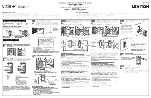
<strong>Single</strong> <strong>Pole</strong> (<strong>One</strong> <strong>location</strong>) <strong>or</strong> 3-<strong>Way</strong> (<strong>Multi</strong>-<strong>location</strong>)<br />
<strong>Digital</strong> <strong>Timer</strong> Switch<br />
Cat. No. VPT24-1P, Lighted<br />
Incandescent-1800W – Resistive/Inductive-15A – Mot<strong>or</strong>-1 HP<br />
120VAC, 60Hz<br />
INSTALLATION INSTRUCTIONS<br />
Step 4b<br />
Co<strong>or</strong>dinating Remote Switch <strong>Timer</strong> Switch<br />
Co<strong>or</strong>dinating Remote Switch (no LED) <strong>Timer</strong> Switch<br />
Hot (Black)<br />
Black<br />
WH BK<br />
(unused)<br />
Green<br />
Ground<br />
WH BK<br />
YL/RD<br />
Load RD<br />
(unused)<br />
YL/RD RD<br />
Line<br />
120VAC, 60Hz<br />
White<br />
BK<br />
YL/RD<br />
Terminal<br />
Screw marked<br />
White (WH)<br />
WH<br />
RD<br />
3<br />
5<br />
Terminal<br />
Screw marked<br />
Yellow/Red<br />
(YL/RD)<br />
1<br />
2<br />
4<br />
WARNINGS AND CAUTIONS:<br />
• Use only one (1) vizia + TM digital timer switch in a multi-<strong>location</strong> circuit with up to 9 co<strong>or</strong>dinating remote switches (without LEDs) <strong>or</strong> up to 4 matching remote switches (with LEDs).<br />
• Maximum wire length from digital timer switch to all installed remotes cannot exceed 300 ft (90 m).<br />
• Disconnect power at circuit breaker <strong>or</strong> fuse when servicing, installing <strong>or</strong> removing fixture.<br />
• Use this device with copper <strong>or</strong> copper clad wire only.<br />
3-<strong>Way</strong> Wiring with Co<strong>or</strong>dinating Remote Switch,<br />
VP0SR-10, (no LED) Application:<br />
Black<br />
White<br />
Yellow/<br />
Red<br />
Green<br />
Green<br />
Ground<br />
Neutral (White)<br />
WIRING TIMER SWITCH:<br />
Connect wires per WIRING DIAGRAM as follows:<br />
NOTE: The timer switch must be installed in a wall box that has a Line Hot<br />
connection.<br />
NOTE: Maximum wire length from timer switch to all installed remotes<br />
cannot exceed 300 ft (90 m).<br />
• Green <strong>or</strong> bare copper wire in wall box to timer switch Green lead.<br />
• Line Hot (common) wall box wire identified (tagged) when removing old<br />
switch to timer switch Black lead.<br />
• First Traveler wall box wire to timer switch Red lead<br />
(note wire col<strong>or</strong>).<br />
• Remove Red insulating label from timer switch Yellow/Red lead.<br />
• Second Traveler wall box wire to the Yellow/Red lead (note wire col<strong>or</strong>).<br />
This traveler from the timer switch must go to the terminal screw on the<br />
remote marked "YL/RD".<br />
• Line Neutral wall box wire to timer switch White lead.<br />
WIRING COORDINATING REMOTE SWITCH (VP0SR-10):<br />
Connect wires per WIRING DIAGRAM as follows:<br />
NOTE: "BK" and "RD" terminals on co<strong>or</strong>dinating remote switch are<br />
unused. Tighten both screws.<br />
NOTE: Maximum wire length from timer switch to last remote cannot<br />
exceed 300 ft (90 m).<br />
• Green <strong>or</strong> bare copper wire in wall box to Green terminal screw.<br />
• Load wall box wire identified (tagged) when removing old switch to First<br />
Traveler (note col<strong>or</strong> as above).<br />
• Second Traveler wall box wire (note col<strong>or</strong> as above) to terminal screw<br />
marked "YL/RD". This traveler from the remote must go to the Yellow/<br />
Red lead on the timer switch.<br />
• Remove White insulating label from terminal screw marked "WH".<br />
• Line Neutral wall box wire to terminal screw marked "WH".<br />
• Proceed to Step 5.<br />
Red<br />
1<br />
2<br />
5<br />
4<br />
3<br />
Step 4c<br />
BK<br />
YL/RD<br />
3-<strong>Way</strong> Wiring with Matching Remote Switch,<br />
VP0SR-1L, (w/LED) Application:<br />
Matching Remote Switch <strong>Timer</strong> Switch<br />
WH<br />
RD<br />
2<br />
1<br />
4<br />
3<br />
5<br />
Additonal Neutral Wire<br />
Matching Remote Switch (w/LED)<br />
Hot (Black)<br />
Line<br />
120VAC, 60Hz<br />
Neutral (White)<br />
WH<br />
BK<br />
Green<br />
Ground<br />
Black<br />
White<br />
Yellow/<br />
Red<br />
Red<br />
Green<br />
<strong>Timer</strong> Switch<br />
NOTE: The timer switch must be installed in a wall box that has a Load<br />
connection. The matching remote must be installed in a wall box with<br />
a Line Hot connection and a Neutral connection. A Neutral wire to the<br />
matching remote needs to be added as shown.<br />
If you are unsure about any part of these instructions, consult an<br />
electrician.<br />
NOTE: Maximum wire length from dimmer to all installed remotes cannot<br />
exceed 300 ft (90 m).<br />
WIRING MATCHING REMOTE SWITCH, VP0SR-1L<br />
(wall box with Line Hot connection):<br />
Connect wires per WIRING DIAGRAM as follows:<br />
• Green <strong>or</strong> bare copper wire in wall box to Green terminal screw.<br />
• Line Hot (common) wall box wire identified (tagged) when removing<br />
old switch and First Traveler to remote terminal screw marked "BK".<br />
• Second Traveler wall box wire from switch to remote terminal screw<br />
marked "YL/RD" (note wire col<strong>or</strong>). This traveler from the remote must<br />
go to the Yellow/Red lead on the timer switch.<br />
• Line Neutral wall box wire to remote terminal screw marked "WH".<br />
WIRING TIMER SWITCH (wall box with Load connection):<br />
Connect wires per WIRING DIAGRAM as follows:<br />
• Green <strong>or</strong> bare copper wire in wall box to timer switch Green lead.<br />
• Load wall box wire identified (tagged) when removing old switch to timer<br />
switch Red lead.<br />
• First Traveler Line Hot to timer switch Black lead.<br />
• Remove Red insulating label from Yellow/Red lead.<br />
• Second Traveler wall box wire (note col<strong>or</strong> as above) to timer switch<br />
Yellow/Red lead. This traveler from the switch must go to the terminal<br />
screw on the remote marked "YL/RD".<br />
• Line Neutral wall box wire to timer switch White lead.<br />
• Proceed to Step 5.<br />
WH<br />
BK<br />
1<br />
2<br />
5<br />
4<br />
3<br />
Green<br />
Ground<br />
YL/RD RD YL/RD<br />
Load<br />
Black<br />
White<br />
Step 5<br />
Testing your Switch pri<strong>or</strong> to mounting in<br />
wall box:<br />
• Position all wires to provide<br />
room in outlet wall box f<strong>or</strong><br />
device.<br />
• Ensure that the w<strong>or</strong>d “TOP” is<br />
facing up on device strap.<br />
• Partially screw in mounting<br />
screws in wall box mounting<br />
holes.<br />
Step 6<br />
NOTE: Dress wires with a bend as shown<br />
in diagram in <strong>or</strong>der to relieve stress when<br />
mounting device.<br />
DI-000-VPT24-02B<br />
• Rest<strong>or</strong>e power at circuit breaker <strong>or</strong> fuse.<br />
• Wait until<br />
the screen.<br />
<strong>or</strong> time is displayed on<br />
• Press pad until locat<strong>or</strong> light is OFF. Load<br />
should turn ON.<br />
If loads do not turn ON, refer to the<br />
TROUBLESHOOTING section.<br />
Switch Mounting:<br />
TURN OFF POWER AT CIRCUIT BREAKER OR FUSE.<br />
• Installation may now be completed<br />
by tightening mounting screws into<br />
wall box. Attach wallplate.<br />
Step 7<br />
Rest<strong>or</strong>e Power:<br />
Rest<strong>or</strong>e power at circuit breaker <strong>or</strong> fuse.<br />
Installation is complete.<br />
NOTE: The <strong>Digital</strong> <strong>Timer</strong> Switch is equipped with an internal<br />
rechargeable battery back-up to keep programmed settings<br />
in the event of a power interruption.
12PM<br />
Event<br />
A<br />
P<br />
MTWThFSaSu<br />
Offset<br />
12AM OPERATION b) Press and hold SET followed by (Override) until stops<br />
• On your timer press<br />
MENU<br />
until SUN appears at the bottom of the<br />
flashing and flashes (approximately 5 seconds).<br />
screen and press SET to confirm your choice.<br />
ICON DEFINITIONS<br />
Press SET to confirm device Reset.<br />
• Use <strong>or</strong> to choose your latitude (N) and press SET to<br />
Permanent override OFF (schedule at a glance not available) c) Product will go through a brief self test and then will begin<br />
confirm your choice.<br />
Temp<strong>or</strong>ary override OFF (when flashing)<br />
to flash. Choose <strong>or</strong> by using <strong>or</strong> until the<br />
• Use <strong>or</strong> to choose your longitude (W) and press SET to<br />
Permanent override ON (schedule at a glance not available)<br />
selected mode appears and pressing SET to confirm your choice.<br />
confirm your choice.<br />
Temp<strong>or</strong>ary override OFF (when flashing)<br />
d) Continue to the programming section f<strong>or</strong> the Mode chosen.<br />
• will be flashing to represent the offset time. Choose the<br />
<strong>Timer</strong> Mode<br />
Daylight<br />
Savings Time<br />
Sun down<br />
Day time<br />
Sun up<br />
PROGRAMMING PRO MODE<br />
1. Setting up the Time, Daylight Savings Time Option and the Date:<br />
amount of time, if any, to turn the load ON/OFF bef<strong>or</strong>e <strong>or</strong> after<br />
Sunup and Sundown by pressing to add time to the Sunup/<br />
Sundown time and use to subtract time from the Sunup/<br />
Sundown time. Press SET to confirm your choice (up to 3 hours<br />
Delete<br />
Setting Timed<br />
A a) will be flashing. Press <strong>or</strong> to select the hour and<br />
press SET to confirm your choice.<br />
and 59 minutes).<br />
• will appear. The time zone closest to the co<strong>or</strong>dinates you<br />
Event number<br />
Days of the week<br />
Offset of<br />
astronomic clock<br />
Battery power<br />
(No AC power)<br />
DST<br />
Events<br />
Longitude/<br />
Latitude<br />
degrees<br />
AM <strong>or</strong> PM<br />
<strong>Timer</strong> schedule<br />
at a glance<br />
Night time<br />
A b) will be flashing. Press <strong>or</strong> to select the minutes and<br />
press SET to confirm your choice.<br />
c) A <strong>or</strong> P will be flashing. Press <strong>or</strong> to select A f<strong>or</strong> AM <strong>or</strong><br />
P f<strong>or</strong> PM and press SET to confirm your choice.<br />
d) will be flashing. Set the daylight savings time mode to OFF<br />
<strong>or</strong> AUTO (f<strong>or</strong> automatic adjustment of daylight savings time)<br />
by using <strong>or</strong> to choose daylight savings time option and<br />
press SET to confirm your choice.<br />
entered will flash. Press SET if this is c<strong>or</strong>rect. If this is not c<strong>or</strong>rect<br />
use <strong>or</strong> to choose your time zone and press SET to<br />
confirm your choice.<br />
b) Setting ON/OFF Events:<br />
MENU<br />
• Press until PRG is in the lower left c<strong>or</strong>ner. Press SET to<br />
enter the programming mode.<br />
SET<br />
• Event 1 will be flashing. Press to choose this event <strong>or</strong> use<br />
NOTE: Daylight Savings Time shall start at 2am on the second<br />
Sunday of March (add one hour) and end at 2am on the first Sunday<br />
to move to the next event and press<br />
event number choice.<br />
SET to confirm your<br />
Programming Menus<br />
of November (subtract one hour).<br />
<strong>Timer</strong> Schedule at a Glance will allow you to quickly see your timers<br />
ON/OFF settings f<strong>or</strong> the day. The displayed segments represent the<br />
time(s) your load will be on. The segment representing the current time<br />
will be flashing.<br />
Backlit LCD display will light up when any button is pressed and will<br />
extinguish 30 seconds after the last button press.<br />
PROGRAMMING GUIDE<br />
Decide which mode is best f<strong>or</strong> your application:<br />
Pro mode <strong>or</strong> Standard mode<br />
Pro Mode provides up to 50 ON/OFF events f<strong>or</strong> any day <strong>or</strong><br />
combination of days, M-Su, M-F, <strong>or</strong> Sa-Su at desired fixed times <strong>or</strong><br />
self adjusting Sunup and Sundown times. In this mode self adjusting<br />
Daylight Savings Time and random modes are also available.<br />
Std Mode provides up to 3 ON/OFF events f<strong>or</strong> M-Su, M-F, <strong>or</strong> Sa-Su<br />
at desired fixed times only. Self adjusting Sunup and Sundown and<br />
Daylight Savings Time are NOT available in Standard Mode.<br />
To exit programming at any time press override button -<br />
To program your device:<br />
a) Perf<strong>or</strong>m a System Reset by gently lifting the VPT24 do<strong>or</strong> from the<br />
bottom of the push pad until an audible click is heard. The do<strong>or</strong> will<br />
stay open while you are programming the device:<br />
Override button<br />
© 2010 Leviton Mfg. Co., Inc.<br />
MENU<br />
SET<br />
12PM<br />
A<br />
Th<br />
12AM DST DST<br />
e) will be flashing. Use <strong>or</strong> to choose the year and<br />
press SET to confirm your choice.<br />
f) will be flashing. Use <strong>or</strong> to choose the month and<br />
press SET to confirm your choice<br />
g) will be flashing. Use <strong>or</strong> to choose the date<br />
and press SET to confirm your choice. The day of week will<br />
automatically adjust.<br />
2. Programming your <strong>Timer</strong> Options:<br />
a) Setting Sunup, Sundown, desired Offset Time and Time Zone:<br />
Sunup and Sundown are automatically adjusted using the<br />
latitude and longitude co<strong>or</strong>dinates of your <strong>location</strong>. To obtain these<br />
co<strong>or</strong>dinates go to www.leviton.com/VPT24 and click on Longitude/<br />
Latitude Co<strong>or</strong>dinates Lookup... Type in your home address and<br />
press enter. Your latitude (N) and longitude (W) co<strong>or</strong>dinates will<br />
be shown on the screen. Write down only the 2 <strong>or</strong> 3 digit number.<br />
Disregard a negative symbol (–) if it preceeds the number.<br />
The time zones are limited to the N<strong>or</strong>th American Continent. The options<br />
you are presented are determined via your longitude in the chart below:<br />
Longitude<br />
TIME ZONE CALCULATIONS<br />
Time Zone<br />
60° – 80°<br />
Eastern<br />
81° – 95°<br />
Eastern, Central<br />
96° – 110°<br />
Central, Mountain<br />
111° – 135°<br />
Mountain, Pacific, Alaskan<br />
136°-143°<br />
Pacific, Alaskan, Hawaii-Aleutian<br />
144°+<br />
Alaskan, Hawaii-Aleutian<br />
12PM<br />
Event<br />
12 AM<br />
• All days of the week will be flashing. Press SET to choose all<br />
days of the week <strong>or</strong> use <strong>or</strong> to scroll through M-F, Sa-<br />
Su, any single day <strong>or</strong> combination of days. NOTE: To choose a<br />
combination of days press SET after each day you want and then<br />
move on to the next day by pressing<br />
scroll using until PRG flashes.<br />
<strong>or</strong> . Continue to<br />
12PM<br />
Event<br />
MTWThFSaSu<br />
12 AM<br />
• When done choosing the desired days PRG in the lower left<br />
c<strong>or</strong>ner will flash. Press SET to confirm the chosen days and<br />
continue on to choosing the event TURN ON TIME.<br />
12PM<br />
Event<br />
12 AM<br />
• At use <strong>or</strong> to choose f<strong>or</strong> time, f<strong>or</strong><br />
Sundown, f<strong>or</strong> Sunup <strong>or</strong> to delete an existing<br />
program and press SET to confirm your choice.<br />
• If is chosen, use <strong>or</strong> to choose the hour and<br />
press SET to confirm your choice. Do the same f<strong>or</strong> minutes.<br />
• At 6:00P press SET to choose a TURN OFF TIME <strong>or</strong> use<br />
<strong>or</strong> to choose f<strong>or</strong> Sundown, f<strong>or</strong> Sunup<br />
<strong>or</strong> to delete an existing program and press SET to confirm<br />
your choice.<br />
• If is chosen, use <strong>or</strong> to choose the hour and<br />
press SET to confirm your choice. Do the same f<strong>or</strong> minutes.<br />
• Continue to set desired events in the same manner. When this<br />
is done press to escape out of programming. If no buttons<br />
are pressed after approximately 30 seconds the device will<br />
automatically exit out of programming mode.<br />
PROGRAMMING STANDARD MODE<br />
To set the clock:<br />
• A will be flashing. Use <strong>or</strong> to choose the hours. Press<br />
SET to confirm your choice.<br />
• The minutes will be flashing. Use <strong>or</strong> to choose the minutes.<br />
Press SET to confirm your choice.<br />
• A f<strong>or</strong> AM <strong>or</strong> P f<strong>or</strong> PM will be flashing. Use <strong>or</strong> to choose the<br />
A <strong>or</strong> P. Press SET to confirm your choice.<br />
• The day of the week will be flashing. Use <strong>or</strong> to choose the<br />
day. Press SET to confirm your choice.<br />
To set ON/OFF Events:<br />
• Press MENU until PRG is in the lower left c<strong>or</strong>ner. Press SET to enter the<br />
•<br />
programming mode.<br />
Event 1 will be flashing. Press<br />
SET<br />
to choose this event <strong>or</strong> use<br />
to move to the next event and press<br />
choice.<br />
SET to confirm your event number<br />
• All days of the week will be flashing. Press<br />
SET<br />
to choose all days of<br />
the week <strong>or</strong> use <strong>or</strong> to scroll through M-F and Sa-Su. Press<br />
SET to confirm your days of the week choice and continue to program<br />
the event ON TIME.<br />
• At use <strong>or</strong> to choose f<strong>or</strong> time, <strong>or</strong> to<br />
delete an existing program and press SET to confirm your choice.<br />
• Use <strong>or</strong> to choose the hour and press SET to confirm<br />
your choice. Do the same f<strong>or</strong> minutes and press SET<br />
choice. Continue to program the event OFF TIME.<br />
to confirm your<br />
• At 6:00P press SET to choose the OFF TIME <strong>or</strong> use <strong>or</strong> to<br />
choose<br />
your choice.<br />
to delete an existing program and press SET to confirm<br />
• Continue to set desired events in the same manner. When you are<br />
done press to escape out of programming. If no buttons are<br />
pressed after approximately 30 seconds the device will automatically<br />
exit out of programming mode.<br />
TIMER OVERRIDES<br />
• Activate Temp<strong>or</strong>ary Override by pressing the push pad to toggle the<br />
load (ON to OFF <strong>or</strong> OFF to ON).<br />
• Activate Permanent Override by pressing and holding the push pad<br />
f<strong>or</strong> several seconds to maintain the load in the current state (either ON<br />
<strong>or</strong> OFF).<br />
CHANGING SETTINGS<br />
• Press MENU until CLK appears at the bottom of the screen . Press<br />
SET to enter this mode. Adjust the clock using <strong>or</strong> and<br />
pressing SET after each setting.<br />
Turning Random Mode ON/OFF (Pro Mode ONLY):<br />
This function will add <strong>or</strong> subtract anywhere from 1 to 20 minutes to each<br />
selected ON and OFF time to create a random pattern.<br />
• Press MENU until RND appears at the bottom of the screen and press<br />
SET to enter this mode.<br />
• Use <strong>or</strong> to toggle between and and press<br />
SET to confirm your choice.<br />
DELETE ALL EVENTS<br />
lf at any time you want to delete all of your programmed events, you can<br />
perf<strong>or</strong>m a DELETE ALL EVENTS function:<br />
a) Gently lift the VPT24 do<strong>or</strong> from the bottom of the push pad until an<br />
audible click is heard.<br />
b) Press and hold<br />
flashing.<br />
SET followed by (Override) until starts<br />
c) Press SET to confirm DELETE ALL EVENTS. All events will be<br />
deleted from your device and the <strong>Timer</strong> Schedule at a Glance will<br />
appear with only the current time segment flashing.<br />
USE IN MULIT-LOCATION APPLICATIONS<br />
When using a remote switch(es) with your vizia + TM 24 hour timer<br />
you will be able to activate the temp<strong>or</strong>ary override <strong>or</strong> the permanent<br />
override from the remote switch. To activate <strong>or</strong> deactivate the temp<strong>or</strong>ary<br />
override press the push pad on the remote switch. To activate<br />
permanent override press and hold the remote switch push pad. Either<br />
of these actions will toggle the state of the load.<br />
TROUBLESHOOTING<br />
• Lights flickering <strong>or</strong> intermittent power to load<br />
- Load has a bad connection.<br />
- Wires not secured firmly with wire connect<strong>or</strong>s of timer switch <strong>or</strong><br />
terminal screws of remote.<br />
• Load does not turn ON and Locat<strong>or</strong> LED does not turn ON<br />
- Circuit breaker <strong>or</strong> fuse has tripped.<br />
- Load is burned out.<br />
- Load Neutral connection is not wired.<br />
• Remote does not operate lights<br />
- Ensure that total wire length does not exceed 300 ft (90 m).<br />
F<strong>or</strong> additional inf<strong>or</strong>mation, contact Leviton’s<br />
Techline at 1-800-824-3005 <strong>or</strong> visit Leviton’s<br />
website at www.leviton.com<br />
Covered by one <strong>or</strong> m<strong>or</strong>e US & F<strong>or</strong>eign<br />
Patents and patents pending<br />
All Rights Including Trade Dress Rights Reserved<br />
• Degree of protection provided: IPX0<br />
• Type of Action: 1CS<br />
FCC COMPLIANCE STATEMENT<br />
This device complies with Part 15 of the FCC Rules. Operation is<br />
subject to following two conditions: (1) this device may not cause<br />
harmful interference, and (2) this device must accept any interference<br />
received, including interference that may cause undesired operation of<br />
the device.<br />
This equipment has been tested and found to comply with the limits<br />
f<strong>or</strong> a Class B <strong>Digital</strong> Device, pursuant to Part 15 of the FCC Rules.<br />
These limits are designed to provide reasonable protection against<br />
harmful interference in a residential installation. This equipment<br />
generates, uses, and can radiate radio frequency energy and, if not<br />
installed and used in acc<strong>or</strong>dance with the instructions, may cause<br />
harmful interference to radio communications. However, there is no<br />
guarantee that interference will not occur in a particular installation. If<br />
this equipment does cause harmful interference to radio <strong>or</strong> television<br />
reception, which can be determined by turning the equipment OFF and<br />
ON, the user is encouraged to try to c<strong>or</strong>rect the interference by one <strong>or</strong><br />
m<strong>or</strong>e of the following measures:<br />
• Re<strong>or</strong>ient <strong>or</strong> relocate the receiving Antenna.<br />
• Increase the separation between the equipment and the receiver.<br />
• Connect the equipment into an outlet on a circuit different from that<br />
to which the receiver is connected.<br />
• Consult the dealer <strong>or</strong> an experienced radio/tv technician f<strong>or</strong> help.<br />
FCC CAUTION<br />
Any changes <strong>or</strong> modifications not expressly approved by Leviton<br />
Manufacturing Co., Inc., could void the user's auth<strong>or</strong>ity to operate the<br />
equipment.<br />
LIMITED 5 YEAR WARRANTY AND EXCLUSIONS<br />
Leviton warrants to the <strong>or</strong>iginal consumer purchaser and not f<strong>or</strong> the benefit of anyone else that this product at the time of its sale by Leviton is free of defects in materials and w<strong>or</strong>kmanship under n<strong>or</strong>mal and proper use f<strong>or</strong> five years from the purchase date. Leviton’s only obligation is to c<strong>or</strong>rect such defects by repair <strong>or</strong> replacement, at its option, if within such five year period the product is returned prepaid, with<br />
proof of purchase date, and a description of the problem to Leviton Manufacturing Co., Inc., Att: Quality Assurance Department, 201 N<strong>or</strong>th Service Road, Melville, New Y<strong>or</strong>k 11747. This warranty excludes and there is disclaimed liability f<strong>or</strong> lab<strong>or</strong> f<strong>or</strong> removal of this product <strong>or</strong> reinstallation. This warranty is void if this product is installed improperly <strong>or</strong> in an improper environment, overloaded, misused, opened,<br />
abused, <strong>or</strong> altered in any manner, <strong>or</strong> is not used under n<strong>or</strong>mal operating conditions <strong>or</strong> not in acc<strong>or</strong>dance with any labels <strong>or</strong> instructions. There are no other <strong>or</strong> implied warranties of any kind, including merchantability and fitness f<strong>or</strong> a particular purpose, but if any implied warranty is required by the applicable jurisdiction, the duration of any such implied warranty, including merchantability and fitness f<strong>or</strong><br />
a particular purpose, is limited to five years. Leviton is not liable f<strong>or</strong> incidental, indirect, special, <strong>or</strong> consequential damages, including without limitation, damage to, <strong>or</strong> loss of use of, any equipment, lost sales <strong>or</strong> profits <strong>or</strong> delay <strong>or</strong> failure to perf<strong>or</strong>m this warranty obligation. The remedies provided herein are the exclusive remedies under this warranty, whether based on contract, t<strong>or</strong>t <strong>or</strong> otherwise.<br />
DI-000-VPT24-02B


