Airborne Gravity 2010 - Geoscience Australia
Airborne Gravity 2010 - Geoscience Australia
Airborne Gravity 2010 - Geoscience Australia

Create successful ePaper yourself
Turn your PDF publications into a flip-book with our unique Google optimized e-Paper software.
Record Record<br />
<strong>2010</strong>/23 <strong>2010</strong>/23<br />
GeoCat GeoCat # #<br />
70673 70673<br />
GSNSW GSNSW<br />
GS<strong>2010</strong>/0457<br />
G EG OE SO CS IC EI NE CN E C E A UA SU TS RT AR LA IL AI<br />
A<br />
<strong>Airborne</strong> <strong>Gravity</strong> <strong>2010</strong> <strong>2010</strong><br />
Abstracts Abstracts from from the the ASEG-PESA ASEG-PESA <strong>Airborne</strong> <strong>Airborne</strong><br />
<strong>Gravity</strong> <strong>Gravity</strong> <strong>2010</strong> <strong>2010</strong> Workshop Workshop<br />
Edited Edited by Richard by Richard Lane Lane<br />
APPLYING APPLYING GEOSCIENCE GEOSCIENCE TO AUSTR TO AUSTR ALIA’S ALIA’S MOST MOST IMPORTANT IMPORTANT CHALLENGES CHALLENGE
<strong>Airborne</strong> <strong>Gravity</strong> <strong>2010</strong><br />
<strong>Airborne</strong> <strong>Gravity</strong> <strong>2010</strong><br />
Abstracts from the ASEG-PESA <strong>Airborne</strong><br />
<strong>Gravity</strong> <strong>2010</strong> Workshop<br />
GEOSCIENCE AUSTRALIA RECORD <strong>2010</strong>/23<br />
AND<br />
GSNSW FILE GS<strong>2010</strong>/0457<br />
Edited by Richard Lane 1<br />
1. Onshore Energy & Minerals Division, <strong>Geoscience</strong> <strong>Australia</strong>, GPO Box 378, Canberra, ACT 2601, <strong>Australia</strong><br />
i
<strong>Airborne</strong> <strong>Gravity</strong> <strong>2010</strong><br />
Department of Resources, Energy and Tourism<br />
Minister for Resources and Energy: The Hon. Martin Ferguson, AM MP<br />
Secretary: Mr Drew Clarke<br />
<strong>Geoscience</strong> <strong>Australia</strong><br />
Chief Executive Officer: Dr Chris Pigram<br />
© Commonwealth of <strong>Australia</strong>, <strong>2010</strong><br />
This work is copyright. Apart from any fair dealings for the purpose of study, research, criticism, or<br />
review, as permitted under the Copyright Act 1968, no part may be reproduced by any process without<br />
written permission. Copyright is the responsibility of the Chief Executive Officer, <strong>Geoscience</strong> <strong>Australia</strong>.<br />
Requests and enquiries should be directed to the Chief Executive Officer, <strong>Geoscience</strong> <strong>Australia</strong>,<br />
GPO Box 378 Canberra ACT 2601.<br />
<strong>Geoscience</strong> <strong>Australia</strong> has tried to make the information in this product as accurate as possible.<br />
However, it does not guarantee that the information is totally accurate or complete. Therefore, you<br />
should not solely rely on this information when making a commercial decision.<br />
ISSN 1448-2177<br />
ISBN 978-1-921781-16-2 (web)<br />
ISBN 978-1-921781-17-9 (print)<br />
GeoCat # 70673<br />
Bibliographic reference:<br />
a) For the entire publication<br />
Lane, R. J. L. (editor), <strong>2010</strong>, <strong>Airborne</strong> <strong>Gravity</strong> <strong>2010</strong> – Abstracts from the ASEG-PESA <strong>Airborne</strong> <strong>Gravity</strong><br />
<strong>2010</strong> Workshop: Published jointly by <strong>Geoscience</strong> <strong>Australia</strong> and the Geological Survey of New South<br />
Wales, <strong>Geoscience</strong> <strong>Australia</strong> Record <strong>2010</strong>/23 and GSNSW File GS<strong>2010</strong>/0457.<br />
b) For an individual paper<br />
Author, I., <strong>2010</strong>, Title of paper, In R. J. L. Lane (editor), <strong>Airborne</strong> <strong>Gravity</strong> <strong>2010</strong> - Abstracts from the<br />
ASEG-PESA <strong>Airborne</strong> <strong>Gravity</strong> <strong>2010</strong> Workshop: Published jointly by <strong>Geoscience</strong> <strong>Australia</strong> and the<br />
Geological Survey of New South Wales, <strong>Geoscience</strong> <strong>Australia</strong> Record <strong>2010</strong>/23 and GSNSW File<br />
GS<strong>2010</strong>/0457.<br />
N.B. Credits and a short description of the images shown on the front cover are given in the first paper<br />
(Introduction to “<strong>Airborne</strong> <strong>Gravity</strong> <strong>2010</strong>”).<br />
ii
<strong>Airborne</strong> <strong>Gravity</strong> <strong>2010</strong><br />
Contents<br />
Introduction to “<strong>Airborne</strong> <strong>Gravity</strong> <strong>2010</strong>”<br />
Richard Lane, Robert Smith, Mark Dransfield, and David Robson .........................................................1<br />
Preparation for flight testing the VK1 gravity gradiometer<br />
J. Anstie, T. Aravanis, P. Johnston, A. Mann, M. Longman, A. Sergeant, R. Smith,<br />
F. Van Kann, G. Walker, G. Wells, and J. Winterflood.............................................................................5<br />
An airborne gravity case study of the Podolsky Deposit, Sudbury Basin<br />
Elizabeth Baranyi and Rob Ellis ............................................................................................................13<br />
Noise analysis and reduction in full tensor gravity gradiometry data<br />
Gary J. Barnes and John M. Lumley ......................................................................................................21<br />
A Turnkey <strong>Airborne</strong> <strong>Gravity</strong> System – Concept to Reality<br />
Nigel Brady ............................................................................................................................................28<br />
Performance of the Gedex High-Definition <strong>Airborne</strong> <strong>Gravity</strong> Gradiometer<br />
Kieran A. Carroll, David Hatch, and Brian Main ....................................................................................37<br />
The <strong>Gravity</strong> Quest<br />
Daniel J. DiFrancesco ............................................................................................................................44<br />
<strong>Airborne</strong> gravimetry and gravity gradiometry at Fugro <strong>Airborne</strong> Surveys<br />
Mark Dransfield, Tiaan Le Roux, and Darren Burrows .........................................................................49<br />
Satellite and airborne gravimetry: their role in geoid determination and<br />
some suggestions<br />
W. E. Featherstone ................................................................................................................................58<br />
Integrated software processing and interpretation methods for airborne gravity<br />
Desmond FitzGerald and Rod Paterson ...............................................................................................71<br />
From gravity gradients to density gradients<br />
Peter Fullagar and Glenn Pears ............................................................................................................79<br />
GOCE gravity gradiometry: Examples of gravity field interpretation from the<br />
South-Central American active continental margins<br />
Hans-Jürgen Götze and Rezene Mahatsente .......................................................................................87<br />
IGMAS+: a new 3D gravity, FTG and magnetic modelling software tool<br />
Hans-Jürgen Götze and Sabine Schmidt ..............................................................................................91<br />
The De Beers Airship <strong>Gravity</strong> Project<br />
David Hatch and Brad Pitts ...................................................................................................................97<br />
The Kauring airborne gravity and airborne gravity gradiometer test site,<br />
Western <strong>Australia</strong><br />
David Howard, Mark Grujic, and Richard Lane .................................................................................. 107<br />
iii
<strong>Airborne</strong> <strong>Gravity</strong> <strong>2010</strong><br />
Acquisition and analysis of the 2007-2009 <strong>Geoscience</strong> BC airborne data<br />
Peter Kowalczyk, Doug Oldenburg, Nigel Phillips, Thi Ngoc Hai Nguyen, and Vicki Thomson ......... 115<br />
A practical software tool for 3D gravity and magnetic modelling<br />
Xiong Li ............................................................................................................................................... 125<br />
Terrain correction and its effect on 3D inversion of<br />
airborne gravity gradiometry data<br />
Yaoguo Li, M. Andy Kass, Kristofer Davis, Marco Braga, and Cericia Martinez ................................ 131<br />
Recent developments with Air-FTG ®<br />
Colm A. Murphy .................................................................................................................................. 142<br />
GT-1A and GT-2A airborne gravimeters: Improvements in design,<br />
operation, and processing from 2003 to <strong>2010</strong><br />
Dan Olson ........................................................................................................................................... 152<br />
Advances in SGL AIRGrav acquisition and processing<br />
Luise Sander and Stephen Ferguson ................................................................................................. 172<br />
The advantages of the full tensor over Gz<br />
Wayne Stasinowsky ........................................................................................................................... 178<br />
The National Elevation Data Framework - a shared digital representation of<br />
<strong>Australia</strong>’s landform and seabed<br />
Phil Tickle ........................................................................................................................................... 183<br />
Using Solid Earth to enhance interpretation<br />
Gregory B. Walker .............................................................................................................................. 188<br />
3D imaging of subsurface structures using migration and<br />
regularized focusing inversion of gravity and gravity gradiometry data<br />
Michael S. Zhdanov, Glenn A. Wilson, and Xiaojun Liu ..................................................................... 194<br />
iv
<strong>Airborne</strong> <strong>Gravity</strong> <strong>2010</strong><br />
Preface<br />
Introduction to “<strong>Airborne</strong> <strong>Gravity</strong> <strong>2010</strong>”<br />
Richard Lane 1 , Robert Smith 2 , Mark Dransfield 3 , and David Robson 4<br />
1 <strong>Geoscience</strong> <strong>Australia</strong> (richard.lane@ga.gov.au)<br />
2 Greenfields Geophysics (greengeo@bigpond.net.au)<br />
3 Fugro <strong>Airborne</strong> Geophysics Pty Ltd (mdransfield@fugroairborne.com.au)<br />
4 Geological Survey of NSW (david.robson@industry.nsw.gov.au)<br />
As members of the <strong>Airborne</strong> <strong>Gravity</strong> <strong>2010</strong> Workshop Committee, we provide this short introduction to<br />
the record of proceedings. This volume contains papers submitted for the <strong>Airborne</strong> <strong>Gravity</strong> <strong>2010</strong><br />
workshop, held in Sydney on August 22, <strong>2010</strong>, in conjunction with ‘ASEG–PESA <strong>2010</strong>’, the ASEG-<br />
PESA 21st International Geophysical Conference and Exhibition. The aims of this workshop were to<br />
review developments in airborne gravity (including airborne gravity gradiometry) that had occurred<br />
since the previous workshop held in 2004 (Lane, 2004), and to anticipate expected developments in<br />
the next 5 to 10 years. These developments include the introduction of new airborne systems,<br />
improvements to related technologies (e.g., GPS and terrain mapping), and developments in data<br />
processing and interpretation.<br />
The morning program mainly addressed operating airborne gravity systems, both the existing systems<br />
and those under development. The afternoon program was directed towards related technologies,<br />
processing and interpretation methods. The overall theme for the day was intended to provoke some<br />
forward thinking and commentary on where we expect or desire to go in the next five to ten years. The<br />
audience was asked to think about these issues, and to contribute ideas and comments during the<br />
final summing up session.<br />
<strong>Airborne</strong> gravity has long been considered the “missing link” in the geophysical toolbox and it has<br />
really only become widely available in the last decade. Several contractors now operate airborne<br />
gravimeters and airborne gravity gradiometers. Several new systems are under development and<br />
others are on the drawing board.<br />
We might anticipate airborne gravity to take a similar development path to that of airborne magnetics<br />
during the last 50 to 60 years, albeit somewhat more rapid. Perhaps this is too simplistic. Magnetic<br />
methods were originally used to detect major magnetic anomalies, often those associated with iron<br />
ore. We rapidly moved beyond this to mapping more subtle magnetic features, but still those generally<br />
considered to be distinct ‘anomalies’. We are now mapping geology in three dimensions using all of<br />
the magnetic data available, plus any possible geological constraints, and also with input from related<br />
geophysical data from other methods (including gravity and seismic).<br />
Accordingly, we might anticipate that airborne gravity will move rapidly beyond “anomaly hunting” to<br />
widespread use in regional and even detailed mapping, incorporating geological constraints and input<br />
from other geophysical measurements. However, there are still some fundamental differences<br />
between gravity and magnetic methods. The range of physical properties affecting gravity data is<br />
much smaller, the effect of terrain is much more important and, at present, the cost is much greater.<br />
We can’t change the first two of these but we do expect that costs will come down and data quality will<br />
improve. With higher quality data, we might even witness more widespread use of airborne gravity to<br />
monitor changes to the distribution of mass on the Earth over time.<br />
To capture the essence of the day and to promote the ongoing development of airborne geophysical<br />
methods, speakers were invited to submit papers for inclusion in a workshop volume. The papers were<br />
reviewed prior to publication in this <strong>Geoscience</strong> <strong>Australia</strong> Record. Participants received a copy at the<br />
workshop, and additional copies of the Record are available on an ongoing basis from <strong>Geoscience</strong><br />
<strong>Australia</strong> (www.ga.gov.au).<br />
1
<strong>Airborne</strong> <strong>Gravity</strong> <strong>2010</strong><br />
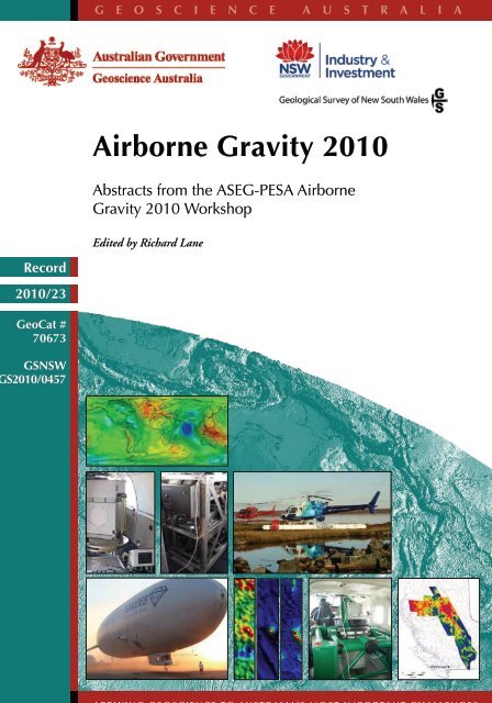
Images on the front cover<br />
The images on the cover of this joint publication <strong>Geoscience</strong> <strong>Australia</strong> Record <strong>2010</strong>/23 and Geological<br />
Survey of New South Wales File GS<strong>2010</strong>/0457 (Figure 1) illustrate a selection of highlights for<br />
airborne gravity technology and applications that have taken place since 2004. These highlights<br />
include the adaptation of existing technologies to produce new acquisition configurations, new<br />
generations of instruments, and application of airborne (including satellite) gravity methods at all<br />
conceivable scales; from global, through regional, to prospect scales.<br />
Figure 1. Montage of images and photographs used on the front cover of joint publication<br />
<strong>Geoscience</strong> <strong>Australia</strong> Record <strong>2010</strong>/23 and Geological Survey of New South Wales File<br />
GS<strong>2010</strong>/0457.<br />
Top row<br />
Image of the first global geoid model based on data from the GOCE satellite gravity gradiometer<br />
system. Image released by the European Space Agency (ESA) in mid-<strong>2010</strong> (GOCE, n.d.). GOCE<br />
(Drinkwater et al., 2007), launched in 2009, provides global gravity gradiometer information with 100<br />
km resolution from an orbit at altitudes of 250 to 300 km. Complete global coverage is achieved on a<br />
61-day repeat cycle, enabling estimates of the time-varying gravity field to be recorded in addition to<br />
the production of an estimate of the long-term mean gravity field that will improve in accuracy as more<br />
and more data are acquired.<br />
Middle row, left to right<br />
Recently released GT-2A airborne gravity system inside a BN-2T Islander aircraft (Olson, <strong>2010</strong>). This<br />
instrument is a major upgrade from the GT-1A instrument launched into the marketplace in 2003.<br />
Photograph supplied by Dan Olson, Canadian Micro <strong>Gravity</strong> Ltd.<br />
Micro-g LaCoste Turnkey <strong>Airborne</strong> <strong>Gravity</strong> System (TAGS) airborne gravity system installed in a US<br />
Navy King Air aircraft. This photograph was taken during the 2009 GRAV-D Alaska-Fairbanks Survey<br />
carried out by the National Oceanic and Atmospheric Administration (NOAA) National Geodetic<br />
Survey (NGS). The survey, funded by National Geospatial Intelligence Agency (NGA), is part of a<br />
2
<strong>Airborne</strong> <strong>Gravity</strong> <strong>2010</strong><br />
program to redefine the North American vertical datum. Photograph supplied by Theresa Diehl, NOAA<br />
- National Geodetic Survey.<br />
The HeliFALCON airborne gravity gradiometer (Dransfield et al., <strong>2010</strong>) and RESOLVE airborne<br />
electromagnetic systems photographed at Norm’s Camp, Ekati, Canada. The digital AGG is mounted<br />
behind the pilot’s seat, with twin LiDAR systems in a pod mounted below and behind the cabin. The<br />
RESOLVE AEM bird is resting on the ground in front of the Aerospatiale 350-B3 helicopter.<br />
Photograph by G. Gooch, supplied by Mark Dransfield, Fugro <strong>Airborne</strong> Geophysics Pty Ltd.<br />
Bottom row, left to right<br />
Bell Geospace Air-FTG ® airborne gravity gradiometer system mounted in a Zeppelin airship (Hatch<br />
and Pitts, <strong>2010</strong>). The stable, slow moving airship provided a perfect platform for acquiring high quality<br />
data for the De Beers Group in Botswana during 2006. Photograph supplied by David Hatch, Gedex<br />
Inc. (formerly with De Beers Group Services).<br />
Images of residual gravity, total magnetic intensity and electromagnetic B-field response in channel 9<br />
from the joint FALCON digital AGG, TMI and TEMPEST survey at the Kauring Test Site (Dransfield<br />
et al., <strong>2010</strong>; Howard et al., <strong>2010</strong>). Each image covers the prospect-scale core region of the test site,<br />
an approximate area of 2 km by 10 km. The survey was flown by Fugro <strong>Airborne</strong> Surveys as a proofof-concept<br />
experiment in a CASA 212 twin-engine aircraft in late 2009. The response of features with<br />
anomalous density, magnetisation and conductivity properties is evident in the central portion of each<br />
image. Images supplied by Mark Dransfield, Fugro <strong>Airborne</strong> Geophysics Pty Ltd.<br />
VK1 airborne gravity gradiometer system mounted in a Cessna 208 aircraft (Anstie et al., <strong>2010</strong>). The<br />
system, being developed by Rio Tinto in collaboration with the Department of Physics at the University<br />
of Western <strong>Australia</strong> (UWA), has the ambitious goal of achieving a noise level better than 1 Eo in a<br />
bandwidth of 1 Hz and is undergoing final preparations prior to flight trials. Photograph supplied by<br />
Theo Aravanis, Rio Tinto Exploration.<br />
Image of regional Bouguer data acquired with an AIRGrav airborne gravity system operated by Sander<br />
Geophysics on behalf of <strong>Geoscience</strong> BC and the Geological Survey of Canada. The survey, covering<br />
a substantial part of British Columbia, Canada, was flown to stimulate mineral and petroleum<br />
investment in British Columbia (Kowalczyk et al., <strong>2010</strong>). Approximately 100,000 line km of data were<br />
acquired on lines spaced at 2 km intervals in four campaigns during the period 2007-2009. The survey<br />
covers an area of approximately 150 km by 1000 km. Image supplied by Luise Sander, Sander<br />
Geophysics.<br />
Units<br />
Physical quantities should be expressed according to the Système International d'Unités (International<br />
System of Units, international abbreviation SI). The Bureau International des Poids et Mesures (BIPM)<br />
is the custodian of this system (http://www.bipm.org/en/si/). As part of a collaborative effort, the U.S.<br />
adaptation of the SI is managed by the National Institute of Standards and Technology (NIST)<br />
(http://www.nist.gov/physlab/div842/fcdc/si-units.cfm).<br />
The SI unit for acceleration is “metre per second squared” (m/s 2 ). The signals encountered in gravity<br />
surveys for exploration are small, and the prefix “micro” is commonly used (micrometre per second<br />
squared, μm/s2). The gal (or Gal), equal to 1 cm/s 2 , is a derived unit for acceleration in the CGS<br />
system of units. A prefix of “milli” is commonly used (milligal, mGal). In rare cases in the literature, a<br />
“gravity unit” (gu) may be encountered. In this publication, the μm/s 2 has been the preferred unit for<br />
gravity measurements, but mGal has been accepted.<br />
1 μm/s 2 = 10 -6 m/s 2<br />
1 mGal = 10 μm/s 2<br />
1 gu = 1 μm/s 2<br />
The gravity gradient is a gradient of acceleration and so the appropriate units are acceleration units<br />
divided by distance units. Thus, “per second squared” (s -2 ) is appropriate in the SI system. Typical<br />
gravity gradients measured in exploration are extremely small, and the prefix “nano” is appropriate in<br />
most circumstances (per nanosecond squared, ns -2 ). The eotvos unit (E or Eo), although not<br />
recognised in either the SI or CGS systems, is used almost universally in geophysics as the unit for<br />
3
<strong>Airborne</strong> <strong>Gravity</strong> <strong>2010</strong><br />
gravity gradient measurements. It is equal to 1 ns -2 . In this publication, the ns -2 and E or Eo have been<br />
accepted as units for gravity gradient measurements.<br />
1 ns -2 = 10 -9 s -2<br />
1 Eo = 1 ns -2<br />
1 Eo = 1 E<br />
Acknowledgments<br />
The <strong>Airborne</strong> <strong>Gravity</strong> <strong>2010</strong> Workshop Organising Committee would like to acknowledge the support of<br />
the ASEG-PESA <strong>2010</strong> Conference Organizing Committee and the Conference Secretariat. Support<br />
from <strong>Geoscience</strong> <strong>Australia</strong> and Industry & Investment NSW (Geological Survey of New South Wales)<br />
helped to make the workshop a success. Printing of copies of this volume for workshop attendees was<br />
kindly managed by Industry and Investment NSW (Geological Survey of New South Wales). Finally, a<br />
vote of thanks goes to the presenters and other participants who contributed to the workshop on the<br />
day and also the authors who prepared the material forming this permanent record of the event.<br />
Richard Lane publishes with the permission of the Chief Executive Officer, <strong>Geoscience</strong> <strong>Australia</strong>.<br />
References<br />
Anstie, J., Aravanis, T., Johnston, P., Mann, A., Longman, M., Sergeant, A., Smith, R., Van Kann, F.,<br />
Walker, G., Wells, G., and Winterflood, J., <strong>2010</strong>, Preparation for flight testing the VK1 gravity<br />
gradiometer: In R. J. L. Lane (editor), <strong>Airborne</strong> <strong>Gravity</strong> <strong>2010</strong> - Abstracts from the ASEG-PESA<br />
<strong>Airborne</strong> <strong>Gravity</strong> <strong>2010</strong> Workshop: Published jointly by <strong>Geoscience</strong> <strong>Australia</strong> and the Geological<br />
Survey of New South Wales, <strong>Geoscience</strong> <strong>Australia</strong> Record <strong>2010</strong>/23 and GSNSW File<br />
GS<strong>2010</strong>/0457.<br />
Dransfield, M., Le Roux, T., and Burrows, D., <strong>Airborne</strong> gravimetry and gravity gradiometry at Fugro<br />
<strong>Airborne</strong> Surveys: In R. J. L. Lane (editor), <strong>Airborne</strong> <strong>Gravity</strong> <strong>2010</strong> - Abstracts from the ASEG-<br />
PESA <strong>Airborne</strong> <strong>Gravity</strong> <strong>2010</strong> Workshop: Published jointly by <strong>Geoscience</strong> <strong>Australia</strong> and the<br />
Geological Survey of New South Wales, <strong>Geoscience</strong> <strong>Australia</strong> Record <strong>2010</strong>/23 and GSNSW<br />
File GS<strong>2010</strong>/0457.<br />
Drinkwater M. R., Haagmans, R., Muzi, D., Popescu, A., Floberghagen, R., Kern, M., and Fehringer,<br />
M., 2007, The GOCE gravity mission: ESA’s first core Earth explorer: Proceedings of the 3rd<br />
International GOCE User Workshop, 6–8 November 2006, Frascati, Italy, ESA SP-627, 1-8.<br />
GOCE, n.d., http://www.esa.int/esaLP/LPgoce.html, accessed 9 July <strong>2010</strong>.<br />
Hatch, D., and Pitts, B., <strong>2010</strong>, The De Beers Airship <strong>Gravity</strong> Project: In R. J. L. Lane (editor), <strong>Airborne</strong><br />
<strong>Gravity</strong> <strong>2010</strong> - Abstracts from the ASEG-PESA <strong>Airborne</strong> <strong>Gravity</strong> <strong>2010</strong> Workshop: Published<br />
jointly by <strong>Geoscience</strong> <strong>Australia</strong> and the Geological Survey of New South Wales, <strong>Geoscience</strong><br />
<strong>Australia</strong> Record <strong>2010</strong>/23 and GSNSW File GS<strong>2010</strong>/0457.<br />
Howard, D., Grujic, M., and Lane, R., <strong>2010</strong>, The Kauring airborne gravity and airborne gravity<br />
gradiometer test site, Western <strong>Australia</strong>: In R. J. L. Lane (editor), <strong>Airborne</strong> <strong>Gravity</strong> <strong>2010</strong> -<br />
Abstracts from the ASEG-PESA <strong>Airborne</strong> <strong>Gravity</strong> <strong>2010</strong> Workshop: Published jointly by<br />
<strong>Geoscience</strong> <strong>Australia</strong> and the Geological Survey of New South Wales, <strong>Geoscience</strong> <strong>Australia</strong><br />
Record <strong>2010</strong>/23 and GSNSW File GS<strong>2010</strong>/0457.<br />
Kowalczyk, P., Oldenburg, D., Phillips, N., Nguyen, T. N. H., and Thomson, V., <strong>2010</strong>, Acquisition and<br />
analysis of the 2007-2009 <strong>Geoscience</strong> BC airborne data: In R. J. L. Lane (editor), <strong>Airborne</strong><br />
<strong>Gravity</strong> <strong>2010</strong> - Abstracts from the ASEG-PESA <strong>Airborne</strong> <strong>Gravity</strong> <strong>2010</strong> Workshop: Published<br />
jointly by <strong>Geoscience</strong> <strong>Australia</strong> and the Geological Survey of New South Wales, <strong>Geoscience</strong><br />
<strong>Australia</strong> Record <strong>2010</strong>/23 and GSNSW File GS<strong>2010</strong>/0457.<br />
Lane, R. J. L. (editor), 2004, <strong>Airborne</strong> <strong>Gravity</strong> 2004 – Abstracts from the ASEG-PESA <strong>Airborne</strong> <strong>Gravity</strong><br />
2004 Workshop: <strong>Geoscience</strong> <strong>Australia</strong> Record 2004/18.<br />
Olson, D., <strong>2010</strong>, GT-1A and GT-2A <strong>Airborne</strong> Gravimeters: Improvements in design, operation, and<br />
processing from 2003 to <strong>2010</strong>: In R. J. L. Lane (editor), <strong>Airborne</strong> <strong>Gravity</strong> <strong>2010</strong> - Abstracts from<br />
the ASEG-PESA <strong>Airborne</strong> <strong>Gravity</strong> <strong>2010</strong> Workshop: Published jointly by <strong>Geoscience</strong> <strong>Australia</strong><br />
and the Geological Survey of New South Wales, <strong>Geoscience</strong> <strong>Australia</strong> Record <strong>2010</strong>/23 and<br />
GSNSW File GS<strong>2010</strong>/0457.<br />
4
<strong>Airborne</strong> <strong>Gravity</strong> <strong>2010</strong><br />
Preparation for flight testing the VK1 gravity<br />
gradiometer<br />
J. Anstie 1 , T. Aravanis 2 , P. Johnston 3 , A. Mann 4 , M. Longman 5 , A. Sergeant 6 , R. Smith 7 ,<br />
F. Van Kann 8 , G. Walker 9 , G. Wells 10 , and J. Winterflood 11<br />
Introduction<br />
1 University of Western <strong>Australia</strong> (anstie@physics.uwa.edu.au)<br />
2 Rio Tinto (theo.aravanis@riotinto.com)<br />
3 University of Western <strong>Australia</strong> (pjjohnst@cyllene.uwa.edu.au)<br />
4 University of Western <strong>Australia</strong> (agm@physics.uwa.edu.au)<br />
5 University of Western <strong>Australia</strong><br />
6 University of Western <strong>Australia</strong> (anthony.sergeant@uwa.edu.au)<br />
7 Greenfields Geophysics (greengeo@bigpond.net.au)<br />
8 University of Western <strong>Australia</strong> (frank@physics.uwa.edu.au)<br />
9 University of Western <strong>Australia</strong><br />
10 Rio Tinto (geoff.wells@riotinto.com)<br />
11 University of Western <strong>Australia</strong> (jwinter@physics.uwa.edu.au)<br />
The VK1 airborne gravity gradiometer is being developed by Rio Tinto in collaboration with the<br />
Department of Physics at the University of Western <strong>Australia</strong> (UWA). The target is to produce an<br />
airborne system with a noise level better than 1 Eö in a bandwidth of 1 Hz. Although achieving this<br />
performance presents significant challenges for both the instrument and the data processing, it is<br />
believed that this level of performance is required for detailed mineral exploration.<br />
This is seen in Figure 1, where the performance of the proposed VK1 instrument is compared with<br />
existing airborne gravity tools, using the response of a number of mineral deposits for reference and<br />
context. The smallest detectable signal is plotted as a function of the wavelength, which for a compact<br />
orebody is approximately twice the spatial extent of the signal. For detailed mineral exploration,<br />
wavelengths below about 1 km are of interest since these wavelengths are relevant for detecting the<br />
response of compact features at depths of less than 500 m. This region is emphasised in the graph by<br />
plotting wavelength on the x-axis with a logarithmic scale. The figure is adapted from a similar graph<br />
published on the Fugro web site (FALCON, n.d.; Drinkwater et al., 2006). The signatures for a number<br />
of ore bodies are shown. Many are marginally detectable by existing airborne gravity gradiometers, but<br />
are easily detectable by an instrument with the target performance of the VK1. Note that none of the<br />
mineral deposits shown are detectable by airborne gravimetry except for the Blair Athol coal deposit<br />
which has a relatively large footprint measuring 4.3 by 4.0 km and a high ~1 g/cm 3 density contrast<br />
with the host.<br />
The analysis presented in Figure 1 focuses on the detection of discrete orebodies, but with improved<br />
signal to noise ratio and better resolution, many more subtle geological features will be mappable.<br />
These features will include lithology and perhaps even alteration zones associated with mineralisation.<br />
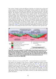
This point is illustrated in Figure 2 a-c, adapted from van Kann (2004) and Dransfield (1994).<br />
5
<strong>Airborne</strong> <strong>Gravity</strong> <strong>2010</strong><br />
Figure 1. Detectable gravity signals as a function of wavelength. The three smooth curves<br />
represent three types of airborne instrument, as indicated by their respective labels. The curve<br />
labelled <strong>Airborne</strong> Gravimetry represents the limit imposed by the accuracy of the GPS error<br />
correction. The curve labelled Falcon <strong>Gravity</strong> shows the performance of the FALCON system,<br />
(FALCON, n.d.), but is also representative of other existing airborne gravity gradiometers. The<br />
noise levels of both these and the VK1 gravity gradiometer have been converted to the<br />
equivalent gravity errors. These are shown in the context of the response of a selection of<br />
compact orebodies, where the wavelength is determined mainly by their depth.<br />
Unlike instruments currently flying, the sensor in VK1 does not rely on springs or paired<br />
accelerometers, but rather the precise balancing of two bars arranged in an “X” fashion, otherwise<br />
known as an Orthogonal Quadrupole Responder (OQR). Changes in the gravitational field in the plane<br />
of the bars will cause the bars to rotate relative to each other. This rotational movement is directly<br />
related to the partial tensor. Although the orientation of the plane of bars can in theory be in any<br />
direction, Rio Tinto/UWA have chosen for the sake of simplicity to arrange them vertically, in one of<br />
two modes;<br />
� along the nominal flight line direction, measuring a combination of the along line and vertical<br />
gravity gradient components, e.g. Gzz – Gxx (where x is the nominal flight direction), or<br />
� at right angles to the nominal line direction, thus a function of the cross-line and vertical gravity<br />
gradient, e.g. Gzz – Gyy.<br />
The orientation of the instrument is selected by the operator and can easily be changed during a<br />
survey, if required.<br />
6
<strong>Airborne</strong> <strong>Gravity</strong> <strong>2010</strong><br />
(a)<br />
(b)<br />
(c)<br />
Figure 2. (a) Noise-free image of simulated Gzz gravity gradient at a terrain clearance of 80 m<br />
over Broken Hill prior to mining. The response was calculated at 50 m centres. The response of<br />
the orebody and its immediate host is recognisable as a sinuous yellow to orange feature at<br />
approximately 5000-9000mE 5000mN. (b) Image of simulated Gzz gravity gradient at a terrain<br />
clearance of 80 m and line spacing of 250 m. The modelled instrument measures the component<br />
Gxy and the combination (Gxx – Gyy)/2, and this is used to obtain the component Gzz by<br />
standard spatial filtering techniques. The instrumental noise corresponds to 12 Eö/√Hz and a<br />
filter with a cut-off wavelength of 500 m has been used. (c) Image of simulated Gzz gravity<br />
gradient at a terrain clearance of 80 m and line spacing of 250 m. The modelled instrument<br />
measures the component Gxy and the combination (Gxx – Gyy)/2, and this is used to obtain the<br />
component Gzz by standard spatial filtering techniques. The instrumental noise corresponds to<br />
1 Eö/√Hz and a filter with a cut-off wavelength of 100 m has been used.<br />
7
<strong>Airborne</strong> <strong>Gravity</strong> <strong>2010</strong><br />
Even in the laboratory, Super conducting Quantum Interference Devices (SQuIDs), operating at liquid<br />
helium temperatures, are required to measure the extremely small rotational movement of the bars. In<br />
the “hostile” airborne environment, movement of the bars will be influenced by normal translational (i.e.<br />
up/down, side to side) and rotational (roll, yaw and pitch) motion of the aircraft. These effects are<br />
minimised by precise balancing of the bars and active rotational stabilisation.<br />
Some details of the VK1 instrument were released at the ASEG conference in Adelaide, in February<br />
2009 (Anstie et al., 2009). At that time, the instrument had been partially assembled and had<br />
demonstrated a measurement of gravity gradient, in the laboratory, with only partial rotational<br />
stabilisation. This paper reports on progress since that date in preparation for flight testing.<br />
State of preparations for flight testing<br />
The “near flight ready” instrument has measured gravity gradients in the laboratory, both with and<br />
without the active stabilisation in operation.<br />
A time record of the gradiometer signal is shown in Figure 3 where a large block of lead is moved<br />
towards then away from the instrument (i.e., at approximately 130 and 240 s). These measurements<br />
were achieved in a relatively stable environment but with significant micro seismic activity and<br />
vibrations produced by researchers working and moving about in the laboratory close to the<br />
instrument.<br />
Figure 3. Time record of the gravity gradient calibration signal (with partial active stabilisation).<br />
Forward modelling of the effects of the lead block were calculated to give a response of 235 Eö. This<br />
provides a useful check of the calibration of the system. The low frequency noise (below about 0.2 Hz)<br />
evident in the figure is much larger than the overall system target noise level of 1 Eö in a bandwidth of<br />
1 Hz, and is partly caused by the absence of thermal control, which had not been commissioned at the<br />
time.<br />
The dominant cause of the noise is the SQuID itself, whose performance was degraded by<br />
environmental factors, predominantly radio frequency interference and cross-talk between the different<br />
SQuIDs in the system. This issue has now largely been dealt with.<br />
The full three axis configuration of the instrument has subsequently been assembled for the first time<br />
and is undergoing testing in the laboratory. The three axis configuration refers to the number of<br />
degrees of freedom in the rotational stabilisation system. The VK1 system has two consecutive stages<br />
of rotational stabilisation for each of the three axes of rotation to reach the instruments performance<br />
objectives, 1 Eö per root Hz.<br />
The first stage consists of a relatively conventional stabilisation platform between the aircraft and the<br />
instrument (Figure 4). Aircraft rotations are sensed with a state-of the-art Inertial Measurement Unit<br />
(IMU) and three gimbal axes controlled by direct-drive torque motors. This platform has already been<br />
extensively flight tested and after some minor engineering modifications has produced performances<br />
which meet or exceed the design specifications.<br />
8
<strong>Airborne</strong> <strong>Gravity</strong> <strong>2010</strong><br />
Figure 4. The rotational stabilisation platform, shown mounted in a Cessna 208. The platform<br />
(coloured green) stabilises the liquid helium dewar (grey cylinder), which houses the instrument.<br />
The instrument is operated in a vacuum inside a sealed chamber, which is immersed in liquid<br />
helium.<br />
The second stage of rotational stabilisation consists of a miniature isolation platform within the<br />
instrument itself and operates at cryogenic temperatures. It incorporates frictionless elastic flexures for<br />
the gimbal bearings and superconducting actuators for control. Superconducting inertial sensors which<br />
measure angular acceleration are used to provide feedback to actively stabilise the instrument. A<br />
rotational stabilisation factor of more than 1000 has already been achieved.<br />
9
<strong>Airborne</strong> <strong>Gravity</strong> <strong>2010</strong><br />
In order to prevent the translational acceleration of the aircraft from degrading the rotational control, all<br />
three gimbal axes must be extremely well balanced. The requirement is that the centre of mass of the<br />
gimbal assembly must be no more than a fraction of a millimetre from the rotation axis. This target has<br />
been exceeded by an order of magnitude.<br />
These isolation stages have now been integrated with the instrument and full three axis active control<br />
has become operational. It has been extensively tested in the laboratory, both statically and on a<br />
recently installed six degrees of freedom flight simulator (Figure 5). This flight simulator can provide<br />
programmed motion with amplitudes approaching 0.5 m and allows most of the aircraft’s motion to be<br />
reproduced, except for the very low frequency components of the spectrum, below about 0.2 Hz. A<br />
second simulator, based on an earth moving machine, can be used to fill-in the low frequency<br />
components.<br />
Figure 5. The instrument being tested on the motion simulator in the laboratory. The simulator<br />
can fully reproduce the aircraft motion in the frequency band from 0.4 Hz up to about 50 Hz in all<br />
six degrees of freedom.<br />
The translational acceleration of the aircraft produces forces which are many orders of magnitude<br />
greater than the gravity gradient signal. The effects of these forces are minimised by extremely precise<br />
balancing of the sensor bars to make their centre of mass coincident with their axis of rotation. A<br />
technique has been developed, which positions the centre of mass to within 1 nanometre (about the<br />
size of an atom) of the axis of rotation but even this precise balance is insufficient to completely<br />
eliminate the effect of the translational acceleration. Three-axis, superconducting linear<br />
accelerometers have been developed to measure and compensate for any residual errors produced<br />
by translation motion. These accelerometers have been tested separately and have been integrated<br />
with the instrument to complete the flight-ready configuration.<br />
The full system is being tested in preparation for flight testing later in <strong>2010</strong>. To facilitate these test<br />
flights, Rio Tinto has collaborated with the Geologic Survey of Western <strong>Australia</strong> and <strong>Geoscience</strong><br />
<strong>Australia</strong> to establish an AGG test range east of Perth, near the hamlet of Kauring (Lane et al., 2009).<br />
Details of the test range are discussed by Howard et al. (<strong>2010</strong>) in these workshop proceedings.<br />
10
<strong>Airborne</strong> <strong>Gravity</strong> <strong>2010</strong><br />
In conjunction with instrument development, considerable effort has been expended on preparations<br />
for utilising the type of data we expect to acquire. A major contribution to any airborne gravity gradient<br />
survey data is likely to be the effects of topography. Since topography may reflect lithology to varying<br />
degrees, these effects are not totally unrelated to the geological signals we want to measure, but they<br />
do complicate the results and must be addressed. In order to utilise the higher instrument sensitivity,<br />
we are striving for better ways to handle topographic effects.<br />
Conventional practise is to apply terrain corrections by calculating the response of the topography<br />
using an assumed, usually homogeneous, density contrast at each observation point, and there are<br />
many tools available to do this. Spatial algorithms vary in the way they discretise the terrain, in their<br />
efficiency and in their ease of use. A number of studies have been conducted both internally and<br />
through external groups to assist in optimising these terrain corrections (e.g., Grujic, <strong>2010</strong>).<br />
It is essential, of course, to have a sufficiently detailed terrain model to undertake the terrain<br />
corrections. In flat area, such as peneplains, freely available SRTM data may suffice. More typically,<br />
given the sensitivity of the VK1 system, “bare-earth” LiDAR may be required to either calculate terrain<br />
corrections or otherwise incorporate terrain in the interpretation process. Such topographic data are<br />
becoming more readily available from a range of sources but, regardless of the accuracy of the terrain<br />
model, the terrain correction calculations will always be limited by the appropriateness of the chosen<br />
density inputs.<br />
Procedures are available to grid the observed survey data, project them onto a smooth surface or a<br />
horizontal plane, and convert the observed quantities into any of the gravity gradient tensor<br />
components. Typically these will be Gzz and Gz. A number of studies have been undertaken to<br />
evaluate and improve these processing tools and this work is ongoing. In addition, Rio Tinto is<br />
developing tools to predict which targets will be visible to the system after allowing for terrain and<br />
terrain clearance effects, expected instrument noise, flight line orientation and host density. These<br />
tools will assist users to optimise survey planning and hence maximise the chances of success in<br />
various terrains and flying conditions (Figure 6).<br />
Figure 6. Example of an AGG simulation, (using Pitney Bowes AGG-SIM software), on shaded<br />
and contoured topography. Green signifies where the specific target has sufficient response from<br />
background to be detectable. Areas where the target is not detectable are shown in red.<br />
Detection is debateable in the grey zones.<br />
11
<strong>Airborne</strong> <strong>Gravity</strong> <strong>2010</strong><br />
Acknowledgements<br />
The VK1 system has been developed entirely within the UWA and is wholly funded and owned by Rio<br />
Tinto. It will initially be deployed in <strong>Australia</strong> on Rio Tinto projects but ultimately will be able to operate<br />
anywhere in the world.<br />
We would like to thank Rio Tinto for permission to publish the current status of the VK1 project and to<br />
thank Richard Lane for his review which greatly improved this paper.<br />
References<br />
Anstie, J., Aravanis, T., Haederle, M., Mann, A., McIntosh, S., Smith, R., Van Kann, F., Wells, G., and<br />
Winterflood, J., 2009, VK-1 - a new generation airborne gravity gradiometer: Extended Abstract,<br />
ASEG-PESA 20th International Geophysical Conference and Exhibition.<br />
Dransfield, M. H., 1994, <strong>Airborne</strong> <strong>Gravity</strong> Gradiometry: Unpub. PhD thesis, University of Western<br />
<strong>Australia</strong>.<br />
Drinkwater, M. R., Haagmans, R., Muzi, D., Popescu, A., Floberghagen, R., Kern, M., and Fehringer,<br />
M., 2006, The GOCE <strong>Gravity</strong> Mission: ESA’s First Core Earth Explorer: 3rd International GOCE<br />
User Workshop, Frascati, Italy, 2006, ESA SP-627, 1-8.<br />
FALCON, n.d., Fugro <strong>Gravity</strong> & Magnetic Services, Fugro, http://www.fugrogravmag.com/FALCON/index.php,<br />
accessed 7 July <strong>2010</strong>.<br />
Grujic, M., <strong>2010</strong>, Optimisation of terrain corrections for practical <strong>Airborne</strong> <strong>Gravity</strong> gradiometer surveys:<br />
Unpub. Bachelor Of Science Honours thesis, Monash University.<br />
Howard, D., Gujic, M., and Lane, R., <strong>2010</strong>, The Kauring airborne gravity and airborne gravity<br />
gradiometer test site, Western <strong>Australia</strong>: In R. J. L. Lane (editor), <strong>Airborne</strong> <strong>Gravity</strong> <strong>2010</strong><br />
Workshop - Abstracts from the ASEG-PESA <strong>Airborne</strong> <strong>Gravity</strong> <strong>2010</strong> Workshop: Published jointly<br />
by <strong>Geoscience</strong> <strong>Australia</strong> and the Geological Survey of New South Wales, <strong>Geoscience</strong> <strong>Australia</strong><br />
Record <strong>2010</strong>/23 and GSNSW File GS<strong>2010</strong>/0457.<br />
Lane, R., Grujic, M., Aravanis, T., Tracey, R., Dransfield, M., Howard, D., and Smith, B., 2009, The<br />
Kauring <strong>Airborne</strong> <strong>Gravity</strong> Test Site, Western <strong>Australia</strong>: Eos Trans. AGU Fall Meeting<br />
Supplement, v. 90(52), Abstract G51A-0656.<br />
Van Kann. F, 2004, Requirements and general principles of airborne gravity gradiometers for mineral<br />
exploration: In R.J.L. Lane (editor), <strong>Airborne</strong> <strong>Gravity</strong> 2004 - Abstracts from the ASEG-PESA<br />
<strong>Airborne</strong> <strong>Gravity</strong> 2004 Workshop: <strong>Geoscience</strong> <strong>Australia</strong> Record 2004/18, 1-5.<br />
12
<strong>Airborne</strong> <strong>Gravity</strong> <strong>2010</strong><br />
An airborne gravity case study of the Podolsky<br />
Deposit, Sudbury Basin<br />
Introduction<br />
Elizabeth Baranyi 1 and Rob Ellis 2<br />
1 Geosoft Inc. (Elizabeth.baranyi@geosoft.com)<br />
2 Geosoft Inc.<br />
A high resolution airborne gravity dataset covering the Podolsky Property, located on the northeast rim<br />
of the Sudbury Basin, has been used as the input for 3-Dimensional (3D) gravity inversion. An initial<br />
inversion without any project-specific constraints was followed up with an inversion incorporating<br />
information gleaned from interpretation of coincident magnetic data coverage over the property and<br />
from a priori knowledge of the geology of the area. The second inversion was deemed to provide a<br />
more reliable estimate of the bulk density distribution for the region. The results indicated that the high<br />
resolution airborne gravity data could be used for mineral exploration applications in this environment.<br />
Geology<br />
The Sudbury Basin in Ontario, Canada, is a Paleoproterozoic geologic structure that is host to a large<br />
number of Ni-Cu-PGE sulphide deposits (Pye et al., 1984). Sudbury and Norilsk, Russia, are the two<br />
largest sulphide nickel camps in the world. The deposits of the Sudbury Basin have been mined for<br />
more than 130 years, and the region continues to be a target region for active exploration.<br />
The Sudbury Igneous Complex (SIC) structure is a deformed and thrusted multi-ring impact basin with<br />
horizontal dimensions of approximately 60 by 27 km, with the long axis oriented in the east-northeast<br />
direction (Figure 1). This complex hosts numerous Ni-Cu-PGE sulphide deposits within portions of the<br />
impact melt that collected in traps, as well as in radiating offset dykes along the footwall rocks, and<br />
within fractured and brecciated footwall rocks.<br />
The Podolsky Property is being developed and explored by Quadra FNX Mining Ltd<br />
(http://www.quadrafnx.com) and is located on the northeast rim of the Sudbury Basin (Figure 1). The<br />
Podolsky Property hosts several copper-nickel-precious metal deposits including the Nickel Ramp<br />
Deposit. A 3D illustration of the known geological structure overlain with the Podolsky Property<br />
boundary is shown in Figure 2.<br />
In the work that is described in this paper, we utilised airborne gravity and LiDAR data that were<br />
acquired during a recent airborne gravity survey flown by Sander Geophysics (Sander and Ferguson,<br />
<strong>2010</strong>). We applied gravity inversion methods to resolve structural detail that was not identified with the<br />
earlier gravity prospecting carried out in this region. A sequence of inversions was carried out, with<br />
location-specific constraints being added to improve the reliability and accuracy of the results.<br />
Constraints were derived from an interpretation of the airborne magnetic data acquired by Aeroquest<br />
in 2004. Drill hole geological information was also used to constrain the bulk density values in the<br />
inversion. The purpose of this work was to demonstrate the information that can be extracted from<br />
high resolution gravity data in relation to the potential for copper-nickel-precious metal mineralization<br />
in the Sudbury region.<br />
13
<strong>Airborne</strong> <strong>Gravity</strong> <strong>2010</strong><br />
Figure 1. Sudbury geology, mine sites, and location of the Podolsky Property.<br />
Figure 2. Perspective view of various geological features of the Podolsky structure with an<br />
overlay of the claim boundary. The mineralization is indicated with arrows. Data compiled by<br />
Quadra FNX Mining Ltd. The figure shows a region with approximate dimensions of 2 km (X,<br />
east-west), 4 km (Y, north-south), and 1.5 km (Z, vertical).<br />
14
<strong>Airborne</strong> <strong>Gravity</strong> <strong>2010</strong><br />
<strong>Airborne</strong> <strong>Gravity</strong><br />
The portion of the gravity field that is relevant to this study is a small fraction of the total measured<br />
gravitational field. Highly accurate measurements are required in order to resolve the geology with any<br />
degree of confidence. Improvements in airborne gravity instrumentation, coupled with large digital data<br />
storage capacity and high performance computing facilities, make it possible to develop more accurate<br />
and reliable interpretations of airborne gravity information.<br />
An extensive literature covers the topics of levelling and reducing airborne gravity data to yield a<br />
coherent residual dataset for further processing and interpretation. We will not review or describe the<br />
steps in detail. Rather, a number of these data processing steps will be mentioned simply as a<br />
preamble to the inversion process.<br />
The airborne gravity data were subjected to time based filtering and levelling. <strong>Gravity</strong> data reduction<br />
steps were then applied to remove portions of the total response which are of little interest for mineral<br />
exploration interpretation. Specifically, these included latitude, Free Air, Bouguer, terrain, Earth<br />
curvature, and tidal corrections (Blakely, 1996). The corrections that are specifically necessary for data<br />
acquired with an airborne system include the Eötvös correction and corrections for the vertical and<br />
horizontal acceleration of the aircraft (Swain, 1996).<br />
LiDAR data for a high resolution terrain model were acquired concurrently with the airborne gravity<br />
data. This model allows accurate Complete Bouguer (terrain) corrections to be calculated and applied<br />
to the gravity data. Figure 3 shows the LiDAR-derived terrain model used for processing the Podolsky<br />
data, superimposed on the known geological structure.<br />
Figure 3. LiDAR surface elevation and subsurface geology data. There is approximately 50 m of<br />
topographic relief.<br />
The terrain corrected airborne gravity data contained short wavelength features that were a<br />
combination of residual terrain artifacts, signals from near-surface geological sources, and acquisition<br />
system noise. To enhance the response of the longer wavelength features related to larger and<br />
deeper sources, a low pass filter with a cut-off half wavelength of 300 metres was applied. Images of<br />
the resultant data are shown in Figure 4 and Figure 5.<br />
15
<strong>Airborne</strong> <strong>Gravity</strong> <strong>2010</strong><br />
Figure 4. Image of Bouguer gravity data, low pass filtered with a half wavelength cut-off of 300 m.<br />
A colour scale for this image is shown in Figure 5. The dynamic range of the gravity data is<br />
approximately 5 mGal.<br />
Figure 5. Perspective view of low-pass filtered airborne gravity data displayed above the LiDAR<br />
surface elevation data and subsurface geological structural data. A low pass filter with half<br />
wavelength cut-off was applied to the gravity data. The gravity and LiDAR data were acquired by<br />
Sander Geophysics in 2009 (Sander and Ferguson, <strong>2010</strong>).<br />
16
<strong>Airborne</strong> <strong>Gravity</strong> <strong>2010</strong><br />
<strong>Airborne</strong> magnetic data were acquired over the Podolsky Property as part of an AeroTEM airborne<br />
electromagnetic survey by Aeroquest in 2004. These data (Figure 6 and Figure 7) provide additional<br />
information that could be used to constrain the gravity inversions that were carried out.<br />
Figure 6. Image of total magnetic intensity (TMI) data shown above gravity, LiDAR surface<br />
elevation and subsurface geological information. The magnetic data were acquired by Aeroquest<br />
in 2004. The dynamic range of the TMI data is approximately 500 nT.<br />
Figure 7. Perspective view of gravity (top) and magnetic (middle) images shown above an image<br />
of the LiDAR surface elevation data (bottom).<br />
17
<strong>Airborne</strong> <strong>Gravity</strong> <strong>2010</strong><br />
<strong>Gravity</strong> inversions<br />
It has become possible with improvements to computer performance and software to routinely model<br />
gravity data using inversion methods. However, it is well known that gravity inversion is an ill-posed<br />
problem, and that any derived density model is non-unique. Therefore, after completing the preprocessing<br />
of the airborne gravity data, the real challenge in gravity inversion is not just to find a model<br />
which has a predicted gravity response in agreement with the observed data, but to find such a model<br />
which is consistent with other geophysical and geological constraints. In this section, we present the<br />
results of an inversion using very general constraints, and follow this up with the results of an inversion<br />
that incorporated the knowledge obtained from interpretation of the airborne magnetic data and a priori<br />
geological knowledge of the region.<br />
<strong>Gravity</strong> inversion with general constraints<br />
As a benchmark, an inversion with general constraints was performed using the methodology and<br />
software described by Li and Oldenburg (1998). The software has been tailored to operate in a multiprocessor/multi-core<br />
environment, the details of which will be presented in a subsequent publication.<br />
For the purpose of clarity, Figure 8 shows the inversion model detail around the Nickel Ramp Deposit<br />
(refer to Figure 2 for the location of this deposit), looking from the SW with the Nickel Ramp Deposit<br />
shown in blue, the contact of the Sublayer Norite with the underlying footwall gneisses shown in<br />
brown, and an isosurface enclosing regions with density contrast of +0.6 g/cm 3 shown in green.<br />
Although we expected there to be a high density feature coincident with the mineralisation, there is an<br />
offset between the mineralization and the recovered high density region. Note however, that gravity<br />
inversion is an ill-posed problem and that this is just the "smoothest" model that "fits" the gravity data<br />
subject to very general constraints. To follow up this result, we utilised constraints derived from<br />
magnetic and geologic information from the region, and reviewed the outcome to see if this would lead<br />
an explorer more directly towards the dense, highly prospective mineralization known to exist in this<br />
location.<br />
Figure 8. Perspective view of the immediate vicinity of the Podolsky Nickel Ramp Deposit, shown<br />
in blue, with the Sublayer Norite contact shown in brown (refer to Figure 2 for the location of this<br />
deposit within the Podolsky Property). The unconstrained smooth gravity inversion response in<br />
this area is shown as a green isosurface enclosing a density contrast +0.6 g/cm 3 .<br />
Geologically and geophysically constrained gravity inversions<br />
Geological constraints can be introduced into inversions in many ways. In this study, we used the<br />
contact surfaces of geologic domains to facilitate changes in physical properties between domains.<br />
The formulation of the inversion algorithm ensures that such changes will only occur where they are<br />
required by the geophysical data (Li and Oldenburg, 1998). We also used the results of magnetic data<br />
inversion to further enhance the gravity inversion by using boundaries defined by rapid changes in the<br />
magnetic susceptibility values as potential boundaries in the density model. We utilised the principle<br />
that boundaries in one physical property domains are likely to be boundaries in another property<br />
18
<strong>Airborne</strong> <strong>Gravity</strong> <strong>2010</strong><br />
domain. A constraint of this type can be used even when the actual relationships between the two<br />
properties are likely to be complicated and are unknown a priori (Lelièvre and Oldenburg, 2009;<br />
Lelièvre et al., 2009).<br />
The outcome of including geologic constraints and auxiliary geophysical constraints in the inversion of<br />
the airborne gravity data is shown in Figure 9. Two density contrast isosurfaces are shown, one at<br />
+1.8 g/cm 3 in magenta and the other at +1.0 g/cm 3 in yellow. Comparing these results with the results<br />
of the previous inversion (Figure 8), we can see that the addition of specific constraints has given rise<br />
to a high density inversion anomaly that is significantly more consistent in location with the known high<br />
density region associated with the nickel mineralization. The fit to the observed gravity data remained<br />
the same. Of particular note, the density anomaly shown in Figure 9 no longer straddles the norite<br />
contact, and it has a density contrast which is higher and more consistent with our expectations for this<br />
type of mineralization.<br />
Figure 9. Perspective view of the immediate vicinity of the Podolsky Nickel Ramp Deposit, as per<br />
Figure 8, with the Podolsky Nickel Ramp Deposit shown in blue and the Sublayer Norite contact<br />
shown in brown. The geologically and magnetically constrained gravity inversion result is shown<br />
as magenta and yellow isosurfaces at density contrasts of 1.8 and 1.0 g/cm 3 .<br />
Conclusions<br />
An interpretation of airborne gravity data has been carried out for the Podolsky Property. This<br />
interpretation was enhanced by having the data acquired using a slow moving helicopter-mounted<br />
airborne gravity system, concurrent acquisition of a detailed LiDAR terrain model, and the application<br />
of inversion processing methods in a modern high performance computing environment.<br />
Inversion of the gravity data with general constraints led to an outcome of limited value. When<br />
supplemented by constraints from magnetic data inversions and from known geological contacts, the<br />
inversion results were deemed to be of greater reliability. It is worth noting that utilisation of boundaries<br />
from one inversion or from independent geological information in a cooperative fashion in a related<br />
inversion would likely improve the results obtained with multi-property classification methods such as<br />
those described by Walker (<strong>2010</strong>).<br />
Acknowledgments<br />
This paper and presentation have been made possible through the support and collaboration of<br />
Geosoft staff with Luise Sander (Sander Geophysics) and John Everest (Quadra FNX Mining Ltd). We<br />
wish to thank Joël Dubé, Kevin Charles, and Martin Bates at Sander Geophysics for providing the<br />
airborne gravity data for the Podolsky Property and for their support to carry out the interpretation of<br />
these data. We also wish to thank Shastri Ramnath and Chris Verzyden at Quadra FNX Mining Ltd<br />
who provided geology, drill hole and aeromagnetic data for the Podolsky Property. Geosoft staff are<br />
19
<strong>Airborne</strong> <strong>Gravity</strong> <strong>2010</strong><br />
thanked for collating the above information and performing a number of inversions to enhance the<br />
information encoded in the high resolution gravity data.<br />
References<br />
Blakely, R. J., 1996, Potential Theory in <strong>Gravity</strong> and Magnetic Applications: Cambridge University<br />
Press, 464 pp.<br />
Li, Y., and Oldenburg, D. W., 1998, 3-D inversion of gravity data: Geophysics, 63, 109-119.<br />
Lelièvre, P. G., and Oldenburg, D. W., 2009, A comprehensive study of including structural orientation<br />
information in geophysical inversions: Geophysical Journal International, 178, 623–637<br />
Lelièvre, P. G., Oldenburg, D. W., and Williams, N. C., 2009, Integrating geological and geophysical<br />
data through advanced constrained inversions: Exploration Geophysics, 40, 334-341.<br />
Pye, E. G., Naldrett, A. J., and Evensen, N. M., 1984, The Geology and Ore Deposits of the Sudbury<br />
Structure: Ontario Geological Survey, Special Volume 1, 603 pp.<br />
Sander, L., and Ferguson, S., <strong>2010</strong>, Advances in SGL AirGRAV acquisition and processing: In R. J. L.<br />
Lane (editor), <strong>Airborne</strong> <strong>Gravity</strong> <strong>2010</strong> - Abstracts from the ASEG-PESA <strong>Airborne</strong> <strong>Gravity</strong> <strong>2010</strong><br />
Workshop: Published jointly by <strong>Geoscience</strong> <strong>Australia</strong> and the Geological Survey of New South<br />
Wales, <strong>Geoscience</strong> <strong>Australia</strong> Record <strong>2010</strong>/23 and GSNSW File GS<strong>2010</strong>/0457.<br />
Swain, C. J., 1996, Horizontal acceleration corrections in airborne gravimetry: Geophysics, 61, 273<br />
276.<br />
Walker, G., <strong>2010</strong>, Using Solid Earth to Enhance Interpretation: In R. J. L. Lane (editor), <strong>Airborne</strong><br />
<strong>Gravity</strong> <strong>2010</strong> - Abstracts from the ASEG-PESA <strong>Airborne</strong> <strong>Gravity</strong> <strong>2010</strong> Workshop: Published<br />
jointly by <strong>Geoscience</strong> <strong>Australia</strong> and the Geological Survey of New South Wales, <strong>Geoscience</strong><br />
<strong>Australia</strong> Record <strong>2010</strong>/23 and GSNSW File GS<strong>2010</strong>/0457.<br />
20
<strong>Airborne</strong> <strong>Gravity</strong> <strong>2010</strong><br />
Noise analysis and reduction in full tensor gravity<br />
gradiometry data<br />
Introduction<br />
Gary J. Barnes 1 and John M. Lumley 2<br />
1 ARKeX Ltd, Cambridge, U.K. (gary.barnes@arkex.co.uk)<br />
2 ARKeX Ltd, Cambridge, U.K. (john.lumley@arkex.com)<br />
The Full Tensor Gradiometer (FTG) consists of three distinct modules known as gravity gradient<br />
instruments each measuring components of differential curvature. When one sums the three inline<br />
outputs to form a quantity known as the ‘inline sum’, the signals cancel leaving a residual that forms a<br />
useful estimate of the overall FTG performance. This quantity not only forms a useful quality control<br />
measure, but also gives insight into the level and colour (spectral shape) of the gradiometer noise.<br />
When analysing survey data, the make-up of the noise can be partitioned into three categories, 1)<br />
shifts in the mean level, 2) correlated noise and 3) uncorrelated high frequency noise. The<br />
uncorrelated noise is generally what is left over after software corrections that reduce the interference<br />
from the linear and angular motions of the aircraft. Apart from filtering and averaging, little can be done<br />
to reduce this part of the noise. Shifts in the mean level can be seen when viewing data from line to<br />
line where data levels typically shift during the survey turns where different operating conditions exist<br />
and the instrument (being on a stabilised platform) acquires a new attitude in the aircraft. Correlated<br />
noise can be caused by environmental changes such as temperature and pressure and is evident<br />
when studying power spectral densities of the inline sum at low frequency. Figure 1 shows the power<br />
spectral density of the inline sum divided by �3 to give the average noise per FTG output during a<br />
typical survey.<br />
PSD [E / �Hz]<br />
60<br />
50<br />
40<br />
30<br />
20<br />
10<br />
10 -3<br />
10 -2<br />
21<br />
Frequency [Hz]<br />
(12, 9.17) mG<br />
(19.5, 14.9) mG<br />
(40.5, 32.2) mG<br />
Figure 1. FTG output channel noise from ARKeX survey data for 3 levels of turbulence as shown<br />
in the legend quantified as (mean level, median level of vertical acceleration power over a 5<br />
second window). Black line shows an empirical noise model fitted to the data.<br />
10 -1
<strong>Airborne</strong> <strong>Gravity</strong> <strong>2010</strong><br />
The data used in this analysis consisted of approximately 250 survey lines that had been accepted by<br />
quality control measures which generally discard lines flown in excessive turbulence. Further details of<br />
the analysis of FTG noise as a function of turbulence can be found in Barnes et al., (<strong>2010</strong>). Some of<br />
the increase in low frequency power in this measure derives from real signal power leaking into the<br />
inline sum measure. The cancellation of the signal is particularly sensitive to the precise calibration of<br />
the FTG output channels and unless test lines flown at high altitude are used, the noise power at low<br />
frequency will tend to be over-estimated. Nevertheless, the red nature of the spectrum does indicate<br />
the presence of correlated noise in the data and to recover the best estimates of the signal, this must<br />
be addressed in the processing strategies.<br />
Low frequency noise or drift is normally handled by levelling procedures that, given an adequate<br />
number of survey line – tie line intersection points, can correct the mean levels together with low order<br />
trends in the data. However, when airborne FTG surveys are flown in a manner where they loosely<br />
follow terrain, also known as ‘2-D drape’, the horizontal intersection points between survey and tie<br />
lines can have large differences in height. In these situations, standard levelling methods become<br />
compromised since they cannot rely on the signal at the intersection points being equal.<br />
To resolve this problem, we use a modification to the equivalent source method that encompasses a<br />
time domain drift model (Barnes, 2008). The variation of the signal with height is then accommodated<br />
by the spatial equivalent source model whereas the mean level and low order drift is handled by a<br />
separate time domain part. After the inversion, the correlated noise absorbed by the time domain part<br />
of the model is discarded leaving an equivalent source model that can be used to forward calculate<br />
data free from the mean level shifts and much of the drift. Such a technique has been used<br />
successfully for surveys performed in mountainous regions where the height difference between<br />
survey and tie lines can be several hundreds of metres.<br />
Method<br />
To model the drift, a simple time interpolation function can be constructed by stringing together piecewise<br />
linear sections at regular intervals (Figure 2).<br />
Figure 2. Exponentially correlated noise time series with a 500 second characteristic time (blue<br />
series) modelled by a piece-wise linear interpolator (red series) with nodal points every 400<br />
seconds (black squares).<br />
The model is entirely specified by the values at the nodal points, v j , therefore making the number of<br />
degrees of freedom equal to the number of nodal points. Collecting these nodal values in a vector v ,<br />
the drift values d at the time instants of the measurements can be expressed as a matrix equation,<br />
22
<strong>Airborne</strong> <strong>Gravity</strong> <strong>2010</strong><br />
d � B v<br />
(1)<br />
where B is a matrix that defines the interpolation. To understand how (1) works, consider the ith<br />
measurement whose acquisition time t i falls between nodal drift values j and j �1<br />
defined at times<br />
t j and t j�1<br />
. The linear interpolated value at time ti ti is given by<br />
� t � � �<br />
i � t j<br />
ti<br />
� t j<br />
d � � � �1�<br />
�<br />
i � v<br />
� � j<br />
v<br />
� � j�1<br />
. (2)<br />
� t j�1<br />
� t j � � t j�1<br />
� t j �<br />
The two terms in brackets represent the matrix elements B i,<br />
j and i,<br />
j�1<br />
23<br />
B .<br />
For most airborne gradiometer surveys with lines of duration less than 30 minutes, there is insufficient<br />
time for complex drift variations to occur and a single linear trend or just simply a bias term<br />
encompassing an entire survey line often suffices.<br />
The space domain part of the inversion follows a standard equivalent source method where the<br />
densities of discrete elements of a model are deduced so that forward calculations from the model fit<br />
the measurements in a least squares sense. The discretisation takes the form of a grid of rectangular<br />
prisms having a top surface following the terrain and a horizontal bottom surface placed below the<br />
minimum point in the topography. This construction therefore naturally builds in the upward<br />
continuation effect in an airborne survey and consequently makes the inversion more immune to high<br />
frequency noise in the data. Having a fixed geometry and solving for the density distributions makes<br />
the inversion linear and suitable for a variety of solvers such as the conjugate gradient algorithm<br />
(Press et al., 1997).<br />
One of the biggest shortcomings of the equivalent source method regards its efficiency. To construct<br />
the inversion one needs to populate a matrix A that represents the unit density forward calculations<br />
from each element in the model to each measurement in the data set. Multiplying this matrix with the<br />
density vector ρ then gives the signals, f s , predicted from the model,<br />
fs � Aρ<br />
(3).<br />
The problem here is that the matrix A is fully populated and extremely large for typical surveys. To<br />
honour the high bandwidth of gradient data, the measurements cannot be heavily re-sampled to<br />
reduce data volume, and similarly, the design of the equivalent source model must be of sufficiently<br />
high resolution.<br />
To make the formulation practicable, we assert that blocks of the model which are distant from the<br />
field point can be grouped together to form a larger averaged block. The averaged block has a top<br />
surface, bottom surface and density all being the average of the individual blocks that it encompasses.<br />
Being distant, this is a valid approximation since the finer details of a field diminish rapidly with<br />
distance from the source. Parts of the model close to the field point are not grouped together thus<br />
preserving their short wavelength contributions to the field. An algorithm decides how to group the<br />
elements using a recursive quadtree subdivision process that starts off with the biggest averaged<br />
block of all – one that encompasses the entire model grid. This block is then subdivided into 4 smaller<br />
sized blocks if its size (defined by the longest x-y dimension) is greater than some factor l multiplied<br />
by the x-y distance between the centre of the block and the field point,<br />
subdivide if � � � � � �2 2<br />
Max L L � l x � x � y � y<br />
(4)<br />
x , y<br />
c f c f<br />
where L x and L y are the block dimensions, �x c , yc<br />
� is the centre of the block and �x f , y f � is the<br />
field point. The factor l controls the level of approximation, where a value of zero would resort back to
<strong>Airborne</strong> <strong>Gravity</strong> <strong>2010</strong><br />
the full calculation with no grouping (i.e., subdivide at every step) and a value of one is generally a<br />
crude approximation.<br />
Figure 3 demonstrates the accuracy of the approximation by evaluating a forward calculation along a<br />
survey line with l values of 0 (representing the exact answer), and 1.5 (representing a crude<br />
approximation level). Even though the error in the approximation level when l was equal to 1.5 is<br />
small compared to the noise in FTG data, it is not necessarily a random variable. Consequently, more<br />
conservative approximation factors for l (e.g., 0.3) are often used for the inversions to ensure<br />
accurate results (note: the result for this value of l is not shown in Figure 3 as it lies within the line<br />
width of the exact answer). By utilising this scheme, the matrix A can be represented as a sparse<br />
matrix with occupancy typically around 1% and therefore offering considerable memory saving and<br />
efficient solution times.<br />
Figure 3. Comparison of full forward calculation (red) and approximate method (blue). The full<br />
calculation required 3.1�10 6 function evaluations, whilst the approximate calculation required only<br />
7900 evaluations. The standard deviation of the differences indicated that the approximation had<br />
an accuracy of 0.6 E.<br />
The time domain drift and space domain equivalent source terms are combined together to form a<br />
single optimisation problem where the density vector ρ and the drift vector v are solved for<br />
simultaneously,<br />
�� � � � � � ��<br />
� 2<br />
Aρ x, y,<br />
z B v t � m x,<br />
y,<br />
z,<br />
minimise � t<br />
(5).<br />
where m(x,y,z,t) represent the measurements. These types of inversion problems invariably require<br />
regularisation to stabilise the solution. In this case adding a regularisation term to prefer smooth<br />
solutions to the density distribution makes sense since the fields from the Earth tend to be spatially<br />
correlated (deGroot-Hedlin and Constable, 1990). Regularisation of this type aids in the correct<br />
assignment between signal and drift as well as improving the robustness of the inversion and the<br />
spatial continuity of the equivalent source model between measurement locations. The drift is<br />
correlated in the time domain whilst the signal is correlated in the space domain. By favouring a<br />
spatially correlated density distribution, drift in the measurements will tend to be accommodated by the<br />
v vector rather than corrupting the ρ vector.<br />
To add further control over the apportioning between the two terms, the drift model can be regularised<br />
using a Tikhonov term. With this form of regularisation, the optimisation described in (5) becomes<br />
2<br />
��Aρ�Bv � m�<br />
� a���ρ��ρ��b�v�v���<br />
minimise (6)<br />
where a is the overall regularisation factor and b controls the relative regularisation between the<br />
density and drift models. The optimum values are determined by running a series of inversions to build<br />
24
<strong>Airborne</strong> <strong>Gravity</strong> <strong>2010</strong><br />
up L-curves (Hansen and O’Leary, 1993) from which the analyst can judge the best compromise<br />
between the fit to the measurements and the complexity of the model.<br />
Results<br />
To demonstrate the above processing procedures, we have created a test FTG data set where the<br />
acquisition pattern and noise derives from a real survey, but the signal derives from a synthetic model<br />
consisting of geological layers with the actual terrain from the survey placed on top. The noise levels<br />
assigned to the survey lines are fairly high and completely swamp the geological signal (the signal<br />
after terrain correction). Careful processing is therefore required to be able to resolve the signals of<br />
interest. Using a forward calculated geological signal makes it possible to accurately assess the error<br />
in the processed data.<br />
The geological model was made sufficiently complex to give a realistic broad band signal similar to<br />
that experienced in real surveys. The equivalent source model was built using the terrain as the top<br />
surface and a flat horizontal plane for the bottom surface. A drift model consisting of a single linear<br />
trend was utilised for each survey line and each of the six measurement channels. An option to break<br />
down the drift along any line into more than one linear section (as shown in Figure 2) was not used<br />
since the survey lines were only 30 km long and did not have sufficient duration for complicated drift<br />
behaviour to materialise.<br />
To solve this relatively small inversion problem, consisting of 2.7�10 5 measurements and 0.9�10 5<br />
source prisms required 0.8 Gb of memory and less than 1 hour of computation. After solution, the<br />
inverted density model was used in isolation from the drift model to forward calculate an enhanced<br />
Gzz distribution both back at the original measurement locations and also on a level grid placed at the<br />
median of the flight height.<br />
By differencing the known signal with these forward calculations, Figure 4 and Figure 5 show how the<br />
error in the processed Gzz varies with frequency in the survey time domain, and inverse wavelength in<br />
the space domain.<br />
PSD [E / � Hz]<br />
10 2<br />
10 1<br />
10 0<br />
10 -1<br />
Measurement noise<br />
Gzz signal<br />
Gzz terrain corrected<br />
Gzz equiv source error<br />
10 -2<br />
Figure 4. Average survey line time domain PSDs.<br />
25<br />
Frequency [Hz]<br />
Referring to Figure 4, at low frequency (1 – 10 mHz), the error in the processed Gzz data is roughly<br />
2.4 times less than the noise level in the original measurements. At higher frequencies, the noise<br />
reduction is greater due to the ability of the equivalent source model to correctly model the exponential<br />
upward continuation that governs the high frequency end of potential field signals. In Figure 5, the<br />
10 -1
<strong>Airborne</strong> <strong>Gravity</strong> <strong>2010</strong><br />
error on Gzz crosses the geological signal at a wavelength around 0.5 – 1 km showing that for this<br />
model, anomaly wavelengths down to this level can be recovered in grids of the processed data.<br />
PSD [Em]<br />
10 3<br />
10 2<br />
10 1<br />
10 0<br />
10 -1<br />
10 -1<br />
Gzz equiv source error<br />
Gzz signal<br />
Gzz terrain corrected<br />
Figure 5. Gridded data radial wavenumber PSDs.<br />
26<br />
10 0<br />
Inverse wavelength [km -1 ]<br />
To demonstrate how well the linear drift model was able to track the low frequency noise, Figure 6<br />
shows the fit for one of the FTG output channels over 4 survey lines. The noise series was low pass<br />
filtered to 0.01 Hz to show more clearly the low order correlated noise. One can see that the shifts in<br />
bias levels dominate and only small linear trends are apparent along these relatively short survey<br />
lines. Both are well fitted by the drift model solution.<br />
Figure 6. Red: low pass filtered noise data, Blue: linear drift model solution. Four survey lines<br />
shown.<br />
10 1
<strong>Airborne</strong> <strong>Gravity</strong> <strong>2010</strong><br />
Conclusions<br />
The augmentation of the equivalent source inversion with a time domain drift model provides a method<br />
of reliably processing potential field data sets that contain significant bias errors or low order drift.<br />
Although a degree of low frequency noise can be removed by standard levelling procedures, these<br />
methods fail when the survey has insufficient cross-over points. The advantage of coupling a drift<br />
model with the equivalent source model is that the drift behaviour is deduced from essentially all the<br />
measurements in the survey leading to a better estimation of the drift terms, but more importantly<br />
allows surveys flown on a draped pattern to be processed.<br />
By employing an approximation technique that groups together source elements distant from the field<br />
point in a recursive fashion, the memory requirements for the inversion are substantially reduced and<br />
consequently the solution time significantly decreased allowing commercially sized data sets to be<br />
processed on desktop personal computers. When comparing the noise levels on the FTG<br />
measurements with the error on the processed Gzz estimate, we see that for low frequencies the<br />
noise reduction is a factor of 2.4 and improves further with frequency.<br />
References<br />
Barnes, G. J., 2008, <strong>Gravity</strong> survey data processing: International Patent application<br />
PCT/GB2008/050059.<br />
Barnes, G., Lumley, J., Houghton, P., and Gleave, R., <strong>2010</strong>, Noise in FTG data and its comparison<br />
with conventional gravity surveys: Expanded Abstracts, EGM <strong>2010</strong> International Workshop -<br />
Adding new value to Electromagnetic, <strong>Gravity</strong> and Magnetic Methods for Exploration, Capri,<br />
Italy, April 11-14 <strong>2010</strong>.<br />
deGroot-Hedlin, C., and Constable, S., 1990, Occam’s inversion to generate smooth, two-dimensional<br />
models from magnetotelluric data: Geophysics 55, 1613 – 1624.<br />
Hansen, P.C., and O’Leary, D. P., 1993, The use of the L-curve in the regularization of discrete illposed<br />
problems: SIAM Journal of Scientific Computing, 14, No.6, 1487 – 1503.<br />
Press, W. H., Teukolsky, S. A., Vetterling, W. T., and Flannery, B. P., 1992, Numerical recipes in C<br />
(2nd ed.): the art of scientific computing: Cambridge University Press.<br />
27
<strong>Airborne</strong> <strong>Gravity</strong> <strong>2010</strong><br />
A Turnkey <strong>Airborne</strong> <strong>Gravity</strong> System – Concept to<br />
reality<br />
Introduction<br />
Nigel Brady 1<br />
1 Micro-g Lacoste Inc. (nigel@microglacoste.com)<br />
<strong>Airborne</strong> gravity surveying has been performed with widely varying degrees of success since early<br />
experimentation with the Lacoste and Romberg dynamic meter in the 1950s (Nettleton et al., 1960).<br />
There are a number of different survey systems currently in operation including relative gravity meters<br />
and gradiometers. However, there are presently a number of roadblocks to achieving high quality<br />
results at a low cost, including market availability for those who wish to own and operate a survey<br />
system.<br />
<strong>Airborne</strong> gravity survey operations have historically had difficulty in producing the desired data quality<br />
at the significant cost advantage claimed per line kilometre when compared with a ground based<br />
survey. <strong>Airborne</strong> surveys represent an expensive investment in equipment and skilled personnel, and<br />
survey operators must provide a reasonable return on that investment to stay viable. There are a<br />
number of factors involved in realizing the potential that airborne gravity offers and if any one of them<br />
is deficient the survey can quickly turn the cost benefit ratio negative.<br />
<strong>Airborne</strong> operations are logistically complex as they require an airport, hangar and FBO (Fixed Base of<br />
Operations) support. Survey operations normally involve at least, pilots, equipment operators, aircraft<br />
maintenance and a geologist/geophysicist for planning and data quality control. Equipment<br />
maintenance and repair downtime can add significant time and cost to the survey. The data quality<br />
itself can be highly reliant on the operator and data processor’s experience and skill levels as well as<br />
the flight characteristics of the aircraft. Finally the data is of much lower value without a very accurate<br />
positioning and timing system.<br />
In 2004, Lacoste and Romberg (now Micro-g Lacoste) decided to build on their success with the newly<br />
developed AirSea II dynamic meter and use that system as the basis for a dedicated airborne<br />
gravity instrument. The Air Sea II was designed as a marine gravity meter but can be adapted to run<br />
in an airborne configuration. Advances in electronics, timing and positioning technology created the<br />
opportunity to refine both the hardware and software, and to develop a truly turnkey system that would<br />
work well for users with little or no airborne gravity experience as well as those with more extensive<br />
experience.<br />
The following goals were set for the new system to ensure that it would meet or exceed the current<br />
requirements of airborne gravity surveying:<br />
� portability and ease of install and setup,<br />
� reliability and ease of operation,<br />
� a repeat line accuracy of 1 milligal or better with an anomaly wavelength resolution of 5 km or<br />
less,<br />
� develop a complete understanding of the system behaviour that allows corrections rather than<br />
filtering to be used for data reduction, and<br />
� provide for fast data processing in the field by an operator for quality control of daily survey<br />
data.<br />
Hardware Solutions<br />
The AirSea II gravity meter (Figure 1) has been shown to have an accuracy at sea of better than<br />
1 milligal in reasonable sea conditions (i.e., 30,000 – 50,000 milligals of vertical acceleration or less).<br />
However, an airborne installation has an inertial acceleration environment that is significantly different<br />
to the low frequency and symmetric accelerations experienced at sea. Air turbulence experienced in<br />
28
<strong>Airborne</strong> <strong>Gravity</strong> <strong>2010</strong><br />
an aircraft tends to be much shorter, sharper and asymmetrical than wave motion, so the damping<br />
characteristics of the sea meter needed to be changed to accommodate this.<br />
Concurrent with the development of the turnkey airborne gravity system (TAGS), a project was carried<br />
out to simplify and improve the air damping that had been used in the Lacoste and Romberg dynamic<br />
meters since their initial design. The result of this project was a magnetic damping system which could<br />
be tuned to reduce the effects of large impulses into the system from turbulence and recover much<br />
more quickly from them. This damping method was incorporated into the airborne system and has<br />
proven to be very effective.<br />
A number of other electronic advancements and features were incorporated into the TAGS system<br />
design including:<br />
� enhanced platform control to maintain the sensor in a level position and reduce time lost<br />
during turns,<br />
� a rubidium oscillator for precise timekeeping and Global Positioning System (GPS)<br />
synchronization down to the ten millisecond level,<br />
� integrated GPS for both UTC time synchronization and differential positioning, and<br />
� high-gain data acquisition and control electronics to reduce response times and minimize<br />
signal filtering.<br />
The system was designed to meet an 18g crash rating to enable aircraft certification to an FAA<br />
restricted flight mode. The operating temperature range was expanded to 0 to 50 °C so that operations<br />
could be performed in the extreme environments encountered in some airborne survey areas. The<br />
various components of the system were integrated into a single frame which also serves to support the<br />
sensor, and the system was designed as a series of modules to allow for easy replacement and thus<br />
minimal downtime should a problem occur. Finally, a high quality UPS provides isolation and<br />
conditioning of the input power and a method to transfer from ground power to aircraft power while<br />
keeping the system fully powered up (Figure 2).<br />
Figure 1. The AirSea II marine gravity<br />
meter.<br />
29<br />
Figure 2. The Turnkey <strong>Airborne</strong> <strong>Gravity</strong><br />
System (TAGS).
<strong>Airborne</strong> <strong>Gravity</strong> <strong>2010</strong><br />
The prototype system hardware was ready for testing in early 2006, and an initial series of ground<br />
based tests was used to prove the concept. For ground testing, the system was mounted in a van and<br />
driven along a straight road to simulate as closely as possible an aircraft flight (Figure 3). Logistically<br />
this type of testing is much easier to setup and far cheaper than aircraft testing (Figure 4). It also has<br />
the advantage of making it much easier to follow the same ground track on every run. A long straight,<br />
flat road is required which also has minimal obstructions for a clear GPS signal. In practice such roads<br />
are not easy to find in Colorado and the test line road has several features which make it less than<br />
ideal, such as elevation changes of a few tens of metres and bumps from road surface irregularities.<br />
The disadvantages, while making the testing more challenging, also served to add some real world<br />
turbulence and flight deviations which allowed for a more rigorous examination of how the system<br />
might respond in an aircraft. The prototype system was tuned until it consistently exceeded the<br />
1 milligal repeatability and 4 km filter resolution specification for a minimum of 4 repeat line passes<br />
during a test (Figure 5). The system was then prepared for a series of airborne tests later in 2006<br />
(Figure 4).<br />
Figure 3. Prototype system set up in a van<br />
for ground based testing in early 2006.<br />
30<br />
Figure 4. Advanced prototype TAGS<br />
mounted in a Piper Navajo for flight testing<br />
in late 2006.
<strong>Airborne</strong> <strong>Gravity</strong> <strong>2010</strong><br />
Figure 5. An example of free-air anomaly values obtained during ground based repeatability tests<br />
using the system mounted in a van.<br />
Software Solutions<br />
Two separate software components are required for the acquisition and processing stages to obtain<br />
optimal data quality from the system (Figure 6 and Figure 7). A large part of the development time was<br />
taken up modelling the behaviour of the platform and writing the processing software so that the<br />
system could truly be operated as a turnkey solution by relatively inexperienced operators. This<br />
resultant “AeroGrav” software allows the user to import the gravity data and the GPS data from both<br />
the onboard system and a base station to quickly produce a Free Air or Bouguer gravity anomaly plot<br />
for any selected survey line.<br />
As has been noted already, one of the more significant problems in airborne gravity is to separate<br />
inertial and gravity components of acceleration. Accurate knowledge of the sensor location in space<br />
allows the inertial acceleration component to be determined. This position information is usually<br />
obtained with a GPS or Inertial Navigation System (INS). Each GPS data point has some noise<br />
associated with it which results in an uncertainty of position. Aircraft survey speed is typically around<br />
60 m/s but can be up to 200 m/s for some applications such as geoid measurements. At these speeds,<br />
position errors can be significant. To reduce the position errors, a base station is used to correct for<br />
atmospheric propagation effects. However, errors will still be present because of timing differences<br />
between the separate receivers. To minimise these GPS timing issues, a new piece of hardware, the<br />
timing unit, was added to the system. The timing unit uses a GPS receiver and a rubidium oscillator to<br />
improve timing synchronization between the GPS receivers and the gravity data to within a few tens of<br />
milliseconds. The AeroGrav software is used to select data segments from the recorded survey data<br />
and combine them with processed differential GPS data to produce free air gravity anomaly plots. The<br />
software can also be used to check the quality of any aspect of the data acquisition process including<br />
31
<strong>Airborne</strong> <strong>Gravity</strong> <strong>2010</strong><br />
aircraft flight characteristics and platform behaviour. The AeroGrav software uses proprietary<br />
algorithms for reduction of the gravity data and incorporates Waypoint GrafNav for GPS processing<br />
(NovAtel, n.d.).<br />
Figure 6. TAGS data acquisition software display.<br />
Figure 7. AeroGrav processing software main display.<br />
32
<strong>Airborne</strong> <strong>Gravity</strong> <strong>2010</strong><br />
The TAGS acquisition software (Figure 6) was designed for minimal user intervention to reduce<br />
operator errors, and to increase reliability and ease of use. The important operating parameters of the<br />
system are displayed on screen to enable ‘at a glance’ quality control (QC) so that a flight line may be<br />
repeated immediately if necessary with minimal wasted flight time. It also features an enhanced<br />
predictive tracking algorithm which calculates the approximate gravity value while the system is in<br />
transit from the airport base to the survey site and during aircraft turns while on survey. This feature<br />
greatly reduces the time the system would otherwise take to settle down into the range where it can<br />
properly read gravity. Aside from QC of the gravity data, the operator selects which flight mode the<br />
system should be in (transit, online, turning or landing) and the system takes care of all of the<br />
appropriate calculations and adjustments. In addition to recording the gravity data on an internal hard<br />
drive, the system outputs data to a serial port which can be connected to a laptop computer for real<br />
time data backup and to also control the main software.<br />
Results<br />
Flight testing of the system began in late 2006 and continued through until mid-2008 using several<br />
different aircraft and locations. Many refinements were made to both hardware and software during the<br />
testing program to bring the system to a consistent level of performance which met the specifications<br />
for both hardware and processing software. At the end of the testing phase, a survey was carried out<br />
over a known test area in South Africa which showed conclusively that the system was meeting the<br />
original performance goals (Figure 8). Periodic testing ensures that system performance is maintained<br />
in terms of repeatability and comparison with ground gravity data (Figure 9 and Figure 10).<br />
Figure 8. Comparison of TAGS data obtained during system testing in South Africa over the<br />
Vredefort Dome and ground vertical gravity data.<br />
33
<strong>Airborne</strong> <strong>Gravity</strong> <strong>2010</strong><br />
Figure 9. System acceptance testing in Florida in early 2009 showing stacked repeat line free-air<br />
anomaly data. The data had a repeatability standard deviation of 0.63 milligals with a 5 km filter<br />
resolution.<br />
Figure 10. Free-air anomaly results obtained during system testing in Florida showing correlation<br />
with ground vertical gravity data. The standard deviation of the differences is 0.51 milligals with a<br />
5 km filter resolution.<br />
34
<strong>Airborne</strong> <strong>Gravity</strong> <strong>2010</strong><br />
Conclusions<br />
The development of a turnkey airborne gravity system represents a major upgrade to the Lacoste and<br />
Romberg dynamic meter. It has met or exceeded its original design goals after several years of<br />
development and refinement. The system has been proven not only with an extensive testing program<br />
but with feedback from survey operators working in a variety of conditions around the world. The<br />
system has proven that it is possible to design a turnkey airborne gravity solution which combines<br />
ease of implementation and operation with robustness and fast data processing to provide excellent<br />
quality data on a range of different aircraft platforms (Johnson, 2009; National Geodetic Survey, n.d.).<br />
Further Developments<br />
There was recognition during the development of the turnkey system that a complete redesign of the<br />
stable platform and electronics would yield further improvements in the performance of the system<br />
which are not possible with the current system. In addition, a better understanding of the platform and<br />
sensor behaviour could be used within the acquisition and processing software to increase data quality<br />
and resolution. A major new effort has now started to build a second generation turnkey system which<br />
will be ready for testing before the end of <strong>2010</strong> (Figure 11).<br />
Figure 11. The engineering prototype for TAGS II (left) next to the current production model<br />
TAGS (right).<br />
Acknowledgments<br />
This summary paper is a distillation of the personal experience of the author and discussions that took<br />
place between the author and Jeffrey MacQueen, who designed the AeroGrav software, and with<br />
Daniel Aliod, who designed the electronics and control software. The various results are shown<br />
courtesy of Fugro <strong>Airborne</strong> Surveys, South Africa, and UTS Geophysics, Perth.<br />
35
<strong>Airborne</strong> <strong>Gravity</strong> <strong>2010</strong><br />
References<br />
Johnson, B., 2009, NOAA Project to Measure <strong>Gravity</strong> Aims to Improve Coastal Monitoring: Science,<br />
325, 378.<br />
LaCoste, L., 1967, Measurements of gravity at sea and in the air: Geophysics, 5, 477–526.<br />
LaCoste, L., Ford, J., Bowles, R., and Archer, K., 1982, <strong>Gravity</strong> measurements in an airplane using<br />
state-of-the-art navigation and altimetry: Geophysics, 47, 832–838.<br />
Nettleton, L. L., LaCoste, L., and Harrison, J. C., 1960, Tests of an airborne gravity meter:<br />
Geophysics, 25, 181-202.<br />
National Geodetic Survey, n.d., GRAV-D: http://www.ngs.noaa.gov/grav-d/index.shtml, accessed 8<br />
August 2008.<br />
NovAtel, n.d., Waypoint® Post-Processing Software: http://www.novatel.com/products/waypointsoftware/waypoint-post-processing-software/,<br />
accessed 8 August <strong>2010</strong>.<br />
Verdun, J., Bayer, R., Klingele, E. E., Cocard, M., Geiger, A., and Halliday, M. E., 2002, <strong>Airborne</strong><br />
gravity measurements over mountainous areas by using a LaCoste & Romberg air-sea gravity<br />
meter: Geophysics, 67, 807-816.<br />
36
<strong>Airborne</strong> <strong>Gravity</strong> <strong>2010</strong><br />
Performance of the Gedex High-Definition <strong>Airborne</strong><br />
<strong>Gravity</strong> Gradiometer<br />
Summary<br />
Kieran A. Carroll 1 , David Hatch 2 , and Brian Main 3<br />
1 Gedex Inc., Toronto Canada (Kieran.Carroll@Gedex.ca)<br />
2 Gedex Inc., Toronto Canada (David.Hatch@Gedex.ca)<br />
3 Gedex Inc., Toronto Canada (Brian.Main@Gedex.ca)<br />
In this paper, we provide a high-level description of the design for the Gedex High Definition <strong>Airborne</strong><br />
<strong>Gravity</strong> Gradiometer (HD-AGG) system, and show the performance achieved by several of the<br />
elements of the system.<br />
Introduction<br />
The goal for Gedex is to develop a commercially viable airborne gravity gradiometer that achieves<br />
post-process performance of 1 E/Hz 1/2 from 0.001 to 1 Hz. At a typical flying height and survey speed<br />
this will produce gravity gradient survey data with a spatial resolution of 50-100 m and an RMS noise<br />
of 1 E. To be productive in a survey aircraft, the system must produce data within this noise<br />
specification while flying at a standard survey height of 80 m in turbulence conditions up to 1 m/s 2 .<br />
The technical hurdles that must be overcome to achieve the noise specifications are formidable. The<br />
instrument must be able to measure displacements of the proof masses to accuracy on the order of<br />
10 -13 m which is about 1000 times smaller than the diameter of a hydrogen atom. As well, no gravity<br />
gradiometer can distinguish between gravity gradient and angular velocity, requiring that the<br />
instrument must be rotationally stabilized to within 0.06 deg/s. To achieve these and other extreme<br />
specifications, Gedex is developing a highly sophisticated system comprised of a number of key subsystems.<br />
The major components that make up the Gedex High-definition <strong>Airborne</strong> <strong>Gravity</strong><br />
Gradiometer system are as follows: gravity gradiometer instrument, cryostat, isolation mount, control<br />
system, aircraft and post-processing software. Figure 1 shows the flight components of the system,<br />
mounted in a Cessna 208. At the time of writing this paper (mid-<strong>2010</strong>), all subsystems have been built,<br />
assemblies of some of these subsystems have been flight-tested, and preparations are underway for<br />
flight-testing the complete, integrated system.<br />
The gravity gradiometer instrument being developed for the HD-AGG is of the Cross-Component<br />
Gradiometer type. This class of instrument has been independently demonstrated (Anstie et al., 2009)<br />
to have acquired signal at sub-eotvos levels in a laboratory setting. The challenge faced by Gedex is<br />
achieving the same level of performance on a moving platform. As it is impossible to build a<br />
gradiometer that is totally insensitive to common mode accelerations, it is important to be able to<br />
minimize the effects of these. One can remove the linear motion-induced noise that can be estimated<br />
with independent accelerometers. As this compensation process cannot totally remove motion induced<br />
noise, Gedex is also developing a motion isolation system to attenuate the aircraft accelerations that<br />
the instrument experiences. The isolation mount will also protect the instrument from large<br />
accelerations.<br />
The end-to-end performance achieved by this system, in terms of the noise level of the gravity<br />
gradiometry data reported after post-processing, is dependent on its various subsystems meeting their<br />
own performance targets. Here we show the level of performance achieved by several of the HD-AGG<br />
subsystems, in particular the gravity gradiometer instrument, the cryostat, the motion isolation mount,<br />
and the post-processing software.<br />
37
<strong>Airborne</strong> <strong>Gravity</strong> <strong>2010</strong><br />
Figure 1. Flight components of the Gedex HD-AGG installed in a Cessna 208.<br />
Instrument<br />
The gravity gradiometer instrument used by Gedex has been developed at the University of Maryland,<br />
and is described by Moody and Paik (2004, 2007). Fundamentally, it comprises pairs of angular<br />
accelerometers that share a common rotation axis, each of which employs an elongated test-mass<br />
(one of which is shown in Figure 2a). The two test-masses in each pair are oriented with their long<br />
axes mutually orthogonal and are supported within housings connected to each other, via bolting, to a<br />
central metering cube structure (Figure 2b). The assembled instrument is shown in Figure 2c. Angular<br />
acceleration of the instrument about the rotation axis of one of the test-mass pairs causes the two testmasses<br />
to rotate in the same direction (“common-mode” motion) with respect to the body of the<br />
instrument, while certain terms of the local gravity gradient tensor cause the two test-masses in each<br />
pair to rotate in opposite directions (“difference-mode” motion).<br />
Figure 2. (a) Angular accelerometer, (b) schematic diagram of sensor, and (c) the assembled<br />
prototype instrument.<br />
38
<strong>Airborne</strong> <strong>Gravity</strong> <strong>2010</strong><br />
The instrument operates at cryogenic temperatures (below 5 K), in order to minimize thermallyinduced<br />
noise, and in order to make use of several useful properties of superconducting materials and<br />
devices; e.g., the instrument employs the Paik transducer (Paik, 1976) to stably resolve motions of the<br />
test-masses to better than 10 -13 m, enabling the instrument to measure gravity gradients less than 1 E.<br />
The Paik transducer employs superconducting niobium test-masses, superconducting-wire inductive<br />
coils, superconducting connecting wiring, and SQUID sensors.<br />
The performance of the instrument is illustrated in Figure 3a and Figure 3b, which are respectively<br />
time-domain and frequency-domain plots of the signals from the instrument’s gravity gradient channel<br />
measured while the instrument was quiescent in the laboratory (mounted in a laboratory cryostat,<br />
subject to seismic noise). These plots show 30 minutes of data which has been corrected for kinematic<br />
acceleration through the use of independent accelerometers. The time-domain data in Figure 3a has<br />
been de-trended using a simple linear correction for bias drift. The units on the vertical axis are eotvos.<br />
It can be seen that the signal did not deviate from the linear trend during this time by more than 2 E.<br />
The RMS variation over this period was 0.6 E.<br />
The data in Figure 3b represents the signal spectral density (i.e., the square-root of the power spectral<br />
density) of the time-domain data in Figure 3a. The noise intensity is below 1 E/Hz 1/2 from 0.05 Hz up to<br />
above 1 Hz.<br />
Figure 3. (a) Time series and (b) signal spectral density plots of 30 minutes of static instrument<br />
test data.<br />
39
<strong>Airborne</strong> <strong>Gravity</strong> <strong>2010</strong><br />
Cryostat<br />
The cryostat performs two functions; it supports the instrument mechanically when subject to aircraft<br />
flight loads, as well as providing the low-temperature environment that the instrument needs in order<br />
for various components within it to superconduct. This low temperature is achieved through the use of<br />
a liquid helium reservoir, within which an evacuated can containing the instrument is submerged, thus<br />
keeping the instrument at a temperature below 5 K. A dewar-type construction is used to insulate the<br />
liquid helium reservoir from ambient temperatures. A key performance target for the cryostat is the rate<br />
of helium boil-off which will dictate the quantity of helium that must be supplied in the field and the<br />
length of time needed between re-fills of the helium reservoir.<br />
Developing the cryostat involved coping with severe design constraints on size and weight, both of<br />
which must be much smaller than for conventional laboratory-grade cryostats. These constraints are<br />
driven by the space and payload capacity of the preferred airborne platform, a Cessna 208. The height<br />
restriction results in unusually short thermal paths between the top plate and the helium reservoir,<br />
which presented a major challenge when designing the structural elements connecting these in a<br />
manner that keeps heat-leaks t to an acceptably low level. In addition, the cryostat must be structurally<br />
much stronger than a typical lab cryostat in order to be certifiably safe to fly, resulting in a relatively<br />
thick structural elements that further exacerbates the difficulty in keeping heat-leaks low enough.<br />
Extensive thermal/structural design work overcame these challenges. As shown in Figure 4 the<br />
cryostat is able to maintain an instrument-space temperature that is stable to less than 0.01 K for<br />
about 27 hours following helium re-fill.<br />
Figure 4. Cryostat thermal performance graph.<br />
40
<strong>Airborne</strong> <strong>Gravity</strong> <strong>2010</strong><br />
Motion isolation mount performance<br />
As described by Moody and Paik (2004), the gravity gradiometer instrument output contains errors<br />
which are caused by translational accelerations and gravitational specific force, and by rotational<br />
accelerations and rotational velocities with respect to inertial space. The amount of acceleration and<br />
angular velocity experienced aboard a fixed-wing aircraft is quite large, and poses one of the main<br />
challenges to obtaining low-noise gravity gradient measurements from an airborne platform. In order to<br />
minimize these errors in the HD-AGG, a motion isolation mount is employed to mechanically<br />
attenuate the amount of acceleration and angular velocity experienced by the instrument.<br />
The motion isolation mount consists of two sets of stages:<br />
� Translational isolation stages: these consist of 3 passive translational isolation stages, one<br />
atop another. Each stage is equipped with springs and dampers, tuned to attenuate motion<br />
relative to the aircraft at frequencies above about 1 Hz. As the equipment supported by these<br />
stages includes the cryostat and instrument, these reduce the accelerations experienced by<br />
the instrument at frequencies above 1 Hz.<br />
� Rotational isolation stages: these consist of an inertially-stabilized platform onto which the<br />
cryostat (containing the instrument) is mounted. An outer stage of the platform is aligned with<br />
the aircraft’s yaw axis, whilst two inner stages are parallel with the aircraft pitch and roll axes<br />
when in their “home” orientations. Each stage is instrumented with relative-angle encoders,<br />
and is actuated by a motor. An active control system is used to estimate the platform’s<br />
orientation, and to command the motors to maintain the platform aligned to the local vertical<br />
and to a desired heading. In this way, the instrument’s angular accelerations and angular<br />
velocity are kept to small values. A key performance target for the rotational isolation stages is<br />
the degree to which it attenuates the aircraft’s angular motion, which can be quite large as the<br />
aircraft manoeuvres to stay on a survey line while buffeted by winds and turbulence.<br />
Insufficient attenuation would result in unacceptably large gravity gradient measurement errors<br />
due to angular velocities and angular accelerations.<br />
Figure 5 illustrates the extent to which the motion of the cryostat (in terms of roll, pitch and yaw<br />
deviations away from a local-horizontal reference frame) is reduced as a result of being supported by<br />
the mount, as compared to the motion it would experience if bolted directly to the airframe of the<br />
aircraft. A flight test was carried out in which the aircraft was flown straight and level, with the pilot<br />
employing the pilot guidance equipment, for a period of 10 minutes. During this segment of the flight,<br />
the vertical acceleration of the aircraft had an RMS value (in the band 0.1-5 Hz) of 0.6 m/s, making the<br />
flying conditions about what we classify as “light turbulence,” the fairly-bumpy flight condition in which<br />
the HD-AGG is designed to operate. Note that during this test flight, the pitch and roll stages of the<br />
rotational isolation mount were carefully balanced pre-flight, while the yaw stage was flown in a known<br />
out-of-balance state. One inertial measurement unit (IMU) was attached to the aircraft’s fuselage, and<br />
a second IMU was attached to the inner stage of the motion isolation mount. The IMUs were oriented<br />
to be approximately aligned with the aircraft’s yaw, pitch and roll axes, and data was taken from them<br />
at 200 Hz.<br />
Figure 5 plots the signal spectral density of orientation data derived via integration within an inertial<br />
navigation system of measurements from the fibre optic gyros in the IMUs. At all frequencies plotted,<br />
the pitch, roll and yaw motions of the aircraft are all attenuated by the mount (i.e., are smaller than the<br />
corresponding aircraft motions). The amount of attenuation about all 3 axes is about a factor of 100 at<br />
0.1 Hz, and at 5 Hz is about a factor of 10 for pitch and 30 for roll. (The imbalance in the yaw stage<br />
during this particular flight is clearly reflected in the relatively modest attenuation of the cryostat’s yaw<br />
motion.) The legend in the plot indicates the RMS values for each quantity, integrated over the 0.1 Hz<br />
to 5 Hz band; the RMS motion of the aircraft is attenuated by the motion isolation mount within this<br />
band by factors of (62, 406, 17) respectively for pitch, roll and yaw. Considerably better yaw<br />
performance has been achieved during flights when the yaw stage was in balance.<br />
41
<strong>Airborne</strong> <strong>Gravity</strong> <strong>2010</strong><br />
Figure 5. Comparison of power spectral density of orientation measurements for the cryostat if it<br />
was bolted directly to the aircraft and when installed in the motion isolation mount.<br />
Post-processing software<br />
There are numerous corrections made to the gravity gradiometer signal during post-processing.<br />
Among the first of these to be applied are corrections for translational accelerations, gravity, angular<br />
accelerations and inertial angular velocities of the instrument. This involves first collecting data from<br />
translational and angular accelerometers which are built into the gradiometer instrument, at the same<br />
time that the gravity gradient signal is collected. These data are then processed to estimate angular<br />
velocities. Next, all of these data are input into an error model, which combines them with preestablished<br />
calibration coefficients in order to estimate their contributions to various terms in the<br />
instrument’s error model. The calibration coefficients are determined pre-flight, via a series of<br />
calibration tests of the instrument using a customized cryostat shaker facility. Finally, these error terms<br />
are subtracted from the measured gradiometer signal. The plot in Figure 3 shows the result of applying<br />
this post-processing step to data collected while the instrument is “quiescent” in the laboratory. In fact,<br />
seismic motion under these conditions results in raw gradiometer signals that are well above 1000 E. It<br />
is only after applying corrections for effects such as translational accelerations and rotational velocities<br />
that the result of less than 1 E RMS is obtained.<br />
Acknowledgements<br />
This paper contains the results of work carried out by the entire HD-AGG development team at Gedex<br />
and the University of Maryland, supported by Gedex’s management and investors.<br />
References<br />
Anstie, J., Aravanis, T., Haederle, M., Mann, A., McIntosh, S., Smith, R., Van Kann, F., Wells, G., and<br />
Winterflood, J., 2009, VK-1 - a new generation airborne gravity gradiometer: Extended Abstract,<br />
ASEG-PESA 20th International Geophysical Conference and Exhibition.<br />
42
<strong>Airborne</strong> <strong>Gravity</strong> <strong>2010</strong><br />
Moody, M. V., and Paik, H. J., 2004, A Superconducting <strong>Gravity</strong> Gradiometer for Inertial Navigation:<br />
Proc. 2004 IEEE Position, Location, and Navigation Symposium (PLANS), Monterey, California,<br />
April 2004.<br />
Moody, M. V., and Paik, H. J., 2007, Cross-component superconducting gravity gradiometer with<br />
improved linearity and sensitivity and method for gravity gradient sensing: US Patent 7,305,879,<br />
issued December 11 2007.<br />
Paik, H. J., 1976, Superconducting tumble-diaphragm transducer for sensitive acceleration<br />
measurements: J. Appl. Phys., 47(3), 1168-1178.<br />
43
<strong>Airborne</strong> <strong>Gravity</strong> <strong>2010</strong><br />
Abstract<br />
The <strong>Gravity</strong> Quest<br />
Daniel J. DiFrancesco 1<br />
1 Lockheed Martin USA (dan.difrancesco@lmco.com)<br />
Since the <strong>Airborne</strong> <strong>Gravity</strong> 2004 workshop held in conjunction with the 2004 ASEG-PESA 17th<br />
Geophysical Conference and Exhibition, there has been a continuing and growing interest in airborne<br />
gravity and gravity gradiometer capabilities. This attention implies both that significant achievements<br />
have been realized and that we have not yet arrived at the optimal capability – and hence that the<br />
quest continues to find even better solutions. Advances in sensor systems, operational efficiency, data<br />
processing, and interpretation have all contributed to improved offerings to the market. Acceptance<br />
and interest by industry is evidenced by the numerous focused workshops, publications, and<br />
investment over the past six years. The prospect for greater usage is tempered by the lack of definitive<br />
success stories and relatively high cost. The future for airborne gravity is also clouded by a number of<br />
questions: How much does airborne gravity help achieve the ultimate objective of finding more<br />
resources? What is the value of information (VOI) to the commercial market? What is lacking in order<br />
for airborne gravity to achieve full potential? With a view towards the future, it is also instructive to ask,<br />
“Where will we be in five years when we convene again?”<br />
Introduction<br />
System Deployments<br />
There has been a steady growth in the number of airborne survey providers and the total usage in the<br />
market over the past 6 years. <strong>Airborne</strong> gravity service providers now number at least 10 companies<br />
worldwide, with an estimated 45 systems in use. These gravity systems include the Sander <strong>Airborne</strong><br />
Inertially Referenced Gravimeter (AIRGrav) system, Canadian Micro <strong>Gravity</strong>’s GT-1A and GT-2A<br />
meters, Micro-g LaCoste TAGS Air III gravity meter, the Russian Chekan-AM mobile gravimeter, and a<br />
few LaCoste & Romberg dynamic gravity meters. It is estimated that nearly 1.1 million line-km are<br />
flown on an annual basis for mining, hydrocarbon, and mapping interests. Additionally, airborne gravity<br />
gradiometer service providers today include ARKeX Ltd., Bell Geospace Inc., and Fugro <strong>Airborne</strong><br />
Surveys Ltd. These companies have deployed gradiometer systems as follows:<br />
ARKeX: 3 Full Tensor Gradiometer (FTG) systems, currently installed on Cessna Grand Caravan and<br />
De Havilland Twin Otter aircraft. Marine surveys are also been conducted using the ARKeX FTG.<br />
Bell Geospace: 3 Full Tensor Gradiometer (FTG) systems, currently installed on Cessna Grand<br />
Caravan and Bassler BT-67 aircraft. Also, the historic Zeppelin airship deployment in South Africa and<br />
Botswana was a joint effort of Bell Geospace and DeBeers.<br />
Fugro <strong>Airborne</strong> Surveys: 4 <strong>Airborne</strong> <strong>Gravity</strong> Gradiometer (AGG – partial tensor) systems incorporated<br />
in the FALCON offering, installed on Cessna Grand Caravan and CASA C-212 fixed-wing aircraft,<br />
and a Eurocopter AS350 helicopter.<br />
It is estimated that 300,000 line-km of gravity gradiometer data are acquired by these companies each<br />
year.<br />
Technology Developments<br />
Many development projects are underway around the world seeking to provide alternative capabilities<br />
to the presently-deployed gravity gradiometer sensors (DiFrancesco, 2008, 2009a). These projects<br />
include:<br />
� AOSense Atomic Interferometer (AI) gravity gradiometer<br />
� ARKeX Exploration <strong>Gravity</strong> Gradiometer (EGG)<br />
44
<strong>Airborne</strong> <strong>Gravity</strong> <strong>2010</strong><br />
� GEDEX High Definition <strong>Airborne</strong> <strong>Gravity</strong> Gradiometer (HD-AGG)<br />
� Gravitec Ribbon Sensor <strong>Gravity</strong> Gradiometer<br />
� University of Twente MEMS gravity gradiometer<br />
� University of Western <strong>Australia</strong> VK-1 gradiometer<br />
These developments have required a significant amount of investment - on the order of $50M (USD)<br />
since 2005. This financial commitment represents another measure of growth and interest in the field<br />
of airborne gravity. As a result of these activities, over 42 worldwide patents have been granted since<br />
2004 for technological advances in the areas of gravity sensor design, data processing, and survey<br />
operations.<br />
Industry Interest<br />
Another indicator of the ‘state of gravity’ is the number of workshops and publications that have been<br />
focused on the topic of gravity. Since 2004, there have been many symposia, special sessions, and<br />
workshops hosted by geophysical societies around the world with the objective of promoting gravity<br />
capabilities. Some of these sessions include:<br />
� SEG’s “Gold Workshop” in Denver, CO, in 2004<br />
� EAGE’s “EGM 2007” and “EGM <strong>2010</strong>” meetings in Capri, Italy<br />
� SEG’s “<strong>Gravity</strong> in Motion” workshop in Las Vegas, NV, in 2008<br />
� EAGE’s “EM, <strong>Gravity</strong> and Magnetic Technologies – Their Impact when Integrated with other<br />
Geophysical and Geological Data” workshop in Rome, Italy, in 2008<br />
� EAGE’s “The Future of Non-Seismic Methods” workshop in Bahrain in 2008<br />
� SAGA’s focused track on gravity gradiometry at the 2009 meeting in Swaziland<br />
� EAGE’s “Advances in High Resolution <strong>Gravity</strong> and Magnetics – Case Studies” workshop in<br />
Barcelona, Spain in <strong>2010</strong><br />
Finally, a search through the leading trade journals in geophysics reveals a growing number of<br />
publications and articles on the topic of gravity surveys and methods. Since 2004, the major<br />
geophysical societies have published articles on airborne gravity as follows:<br />
� EAGE (including First Break, Near Surface Geophysics and Geophysical Prospecting): a total<br />
of 116 articles and extended abstracts<br />
� SEG (including The Leading Edge and Geophysics): a total of 53 articles<br />
� ASEG (including Preview and Exploration Geophysics): a total of 19 articles<br />
The significance of gravity<br />
Reset from ASEG <strong>Gravity</strong> Workshop 2004<br />
The <strong>Airborne</strong> <strong>Gravity</strong> 2004 workshop held in conjunction with the ASEG-PESA Conference in Sydney<br />
provided a forum for identifying the state-of-the-art in airborne gravity. A few excerpts provide a<br />
benchmark from that time for airborne gravity and gravity gradiometer system performance:<br />
� Stephan Sander from Sander Geophysics Ltd. (SGL) speaking of the AIRGrav system stated,<br />
“Final grids created with low-pass filters in the 2 – 4 km range have noise standard deviations<br />
between 0.15 and 0.3 mGal.” (Sander et al., 2004).<br />
� Canadian Micro <strong>Gravity</strong> representative Andy Gabell noted performance of the GT-1A system<br />
as follows: “Given an acquisition speed of 50 to 70 m/s and filter length of around 100 s,<br />
resolution (standard deviation) is 0.6 mGal or better for a half-wavelength of 2.0 to 3.5 km”<br />
(Gabell et al., 2004).<br />
� Referring to the Bell Geospace FTG, Colm Murphy indicated, “The system currently achieves<br />
resolution of approximately 5 Eo when low-pass filtered to remove wavelengths less than 400<br />
to 600 m” (Murphy, 2004).<br />
� Mark Dransfield, then working with BHPBilliton, noted performance of the FALCON system<br />
as follows: “Typical difference noise in the horizontal curvature gradients is between 4 and 7<br />
Eo as turbulence increases to 1 m/s 2 . Occasionally we obtain noise down below 3.5 Eo.”<br />
(using a 300 m wavelength) (Dransfield and Lee, 2004).<br />
45
<strong>Airborne</strong> <strong>Gravity</strong> <strong>2010</strong><br />
That was 2004. In 2007, David Hatch (then of DeBeers) stated, “Air-FTG® data acquired on a<br />
Zeppelin NT airship at a line spacing of 150 m resulted in an RMS noise level of 1.7 Eo with 100 m<br />
wavelength resolution along flight-lines” (Hatch et al., 2007, <strong>2010</strong>). This appears to be the best<br />
published performance figure for airborne gravity gradient data. So, advances are being made. What<br />
is the state-of-the-practice today? Have systems and processes improved significantly since 2004?<br />
Since 2007? Hopefully, we will hear an updated status on airborne gravity activity during this<br />
workshop.<br />
Value of Information<br />
Typical airborne gravity surveys today cost between $40 and $70 (USD) per line-km, depending on<br />
survey size and other logistical factors. Costs for airborne gravity gradient surveys are higher, on the<br />
order of $130 to $175 (USD) per line-km. Based on the previous stated annual estimates of 1.1M linekm<br />
for airborne gravity and 300,000 line-km for gravity gradiometry, this represents industry revenues<br />
of $44M to $77M (gravity) and $39M to $53M (gradiometry). Another way of saying this is that<br />
exploration budgets must include appropriations between $83M and $130M simply to sustain current<br />
activity for airborne gravity and gradiometry. Is this sustainable? Is there growth in these numbers? Is<br />
the value received from these expenditures commensurate with the outlay? These questions can be<br />
answered in less quantitative ways by asking the following questions:<br />
� Are repeat customers coming back for more survey work?<br />
� Are new customers emerging as capability is demonstrated?<br />
� Are new customers waiting for advances (technically, operationally, answer products, etc.)<br />
before committing?<br />
� When given a choice, are potential customers spending their limited exploration budgets on<br />
other things?<br />
Other Opportunities<br />
While exploration is the prime focus for airborne gravity activity today, looking at adjacent opportunities<br />
provides for interesting consideration. For example, gravity and gradiometry are well suited for many<br />
near surface applications such as civil engineering, environmental monitoring, water detection,<br />
tectonic monitoring, and earthquake prediction (Hodges et al., <strong>2010</strong>). Will growth into these areas<br />
provide a significant upside for current practitioners? Will it open doors for newer developments? If<br />
growth is to be achieved in the application of airborne gravity, then new prospects will need to be<br />
vigorously pursued.<br />
<strong>Airborne</strong> gravity going forward<br />
Strategy<br />
A recent presentation by Dr. Vijay Govindarajan from the Tuck School of Business at Dartmouth<br />
University highlighted a number of key items for consideration when strategy and growth plans are<br />
considered (Govindarajan, <strong>2010</strong>; Kelley, 2009a, 2009b). Strategy can be defined as “innovation” and<br />
“next practices.” In other words, it involves moving beyond what is known and comfortable and<br />
expanding into new constructs and ways of doing things. Essentially, we all have two current<br />
responsibilities: (1) make money for today, and (2) plan for making money in the future. An approach<br />
for pursuing these objectives can be broken into three parts: (1) manage the present, (2) selectively<br />
forget the past, and (3) create the future. One of the things that can hinder growth and progress is<br />
being wed to the past. “We’ve always done it this way” is a common refrain in any industry. If we look<br />
back on the exploration industry, we can see that things have indeed progressed over the years.<br />
<strong>Airborne</strong> gravity was first introduced in the late 1950’s. It has progressed to the levels of exceptional<br />
performance today by virtue of moving forward and building upon success. <strong>Airborne</strong> gravity<br />
gradiometry surveys only started in 1998, and since those early efforts, we can see continual<br />
improvement. So, we aren’t doing things the same way as we did in the 1950’s – or the 1990’s. The<br />
question is, “What should we be planning for in the decades ahead?” What will airborne geophysical<br />
exploration look like in 2025? In 2050? We would expect that there will be an increased demand for<br />
commodities as population grows and countries/economies develop. This will necessitate a continuing<br />
need for exploration to find new resources to support the growth. Can we assume that the way we do<br />
things today will be adequate to meet the demands of tomorrow?<br />
46
<strong>Airborne</strong> <strong>Gravity</strong> <strong>2010</strong><br />
The Quest<br />
A few final thoughts are provided on the gravity quest. A quest is an act of seeking. It could be called a<br />
search, pursuit, investigation, mission, hunt, or expedition. In any event, it involves the act of looking<br />
ahead. So, we should ask questions that will be directive to help us reach our destination. What will<br />
exploration look like in 2015? In 2025? In 2050? If I am pressed to predict or forecast how the future<br />
will look, here are some of the key elements I would include (DiFrancesco, 2009b):<br />
1. <strong>Airborne</strong> surveys will be flown at faster speeds and coverage rates and in higher dynamic<br />
conditions.<br />
2. Scalar gravity and gradients will be measured with greater precision.<br />
3. Survey costs for airborne gravity will be significantly lower.<br />
4. Integrated scalar gravity plus second and third order tensor gradient data will be available in a<br />
single service offering.<br />
5. <strong>Gravity</strong> (scalar and tensor), along with both magnetics and EM, will be configured on the<br />
same survey aircraft so that an economy of scale is realized.<br />
6. A series of significant exploration successes will be attributed to gravity and gradiometry.<br />
7. The market will really understand what gravity and gradiometry can do for them.<br />
Conclusion<br />
It is readily apparent that airborne gravity is becoming a mainstay of the exploration industry.<br />
Technical and operational advances in the past few years have enhanced the capability, and there is a<br />
foundational acceptance for the benefits of these techniques. A growing understanding of gravity<br />
benefits and utility is being communicated to the market in the form of workshops, technical<br />
publications, and first-hand experience. It is also clear that the way things have been done in the past<br />
will not support the needs for the next generation of explorationists. New technology, new approaches,<br />
and out-of-the-box thinking will be necessary to keep airborne gravity relevant and lead the charge to<br />
further exploration success. It is also important to emphasize that the outcome of this workshop must<br />
be more than just the sharing of information and status, but the provision of vision and direction for the<br />
future.<br />
References<br />
DiFrancesco, D., Grierson, A., Kaputa, D., and Meyer, T., 2009a, <strong>Gravity</strong> gradiometer systems -<br />
advances and challenges: Geophysical Prospecting, 57, 615-623.<br />
DiFrancesco, D., Kaputa, D., and Meyer, T., 2008, <strong>Gravity</strong> gradiometer systems – advances and<br />
challenges: Preview, 133, 30-36.<br />
DiFrancesco, D., Meyer, T., Christensen, A., and FitzGerald, D., 2009b, <strong>Gravity</strong> gradiometry – today<br />
and tomorrow: Expanded Abstracts, 11 th SAGA Biennial Technical Meeting and Exhibition,<br />
Swaziland, 16-18 September 2009, 80-83.<br />
Dransfield, M. H., and Lee, J. B., 2004, The FALCON® airborne gravity gradiometer survey systems:<br />
In R.J.L. Lane (editor), <strong>Airborne</strong> <strong>Gravity</strong> 2004 – Abstracts from the ASEG-PESA <strong>Airborne</strong><br />
<strong>Gravity</strong> 2004 Workshop: <strong>Geoscience</strong> <strong>Australia</strong>n Record 2004/18, 15-19.<br />
Gabell, A., Tuckett, H., and Olson, D., 2004, The GT-1A mobile gravimeter: In R.J.L. Lane (editor),<br />
<strong>Airborne</strong> <strong>Gravity</strong> 2004 – Abstracts from the ASEG-PESA <strong>Airborne</strong> <strong>Gravity</strong> 2004 Workshop:<br />
<strong>Geoscience</strong> <strong>Australia</strong>n Record 2004/18, 55-61.<br />
Govindarajan, V., <strong>2010</strong>, Strategy is innovation: Presented to William F. Achtmeyer Center for Global<br />
Leadership -Tuck School of Business at Dartmouth University.<br />
Hatch, D. M., Murphy, C., Mumaw, G., and Brewster, J., 2007, Performance of the Air-FTG System<br />
aboard an airship platform: Preview, 127, 17 - 22.<br />
Hatch, D., and Pitts, B., <strong>2010</strong>, The De Beers Airship <strong>Gravity</strong> Project: In R. J. L. Lane (editor), <strong>Airborne</strong><br />
<strong>Gravity</strong> <strong>2010</strong> - Abstracts from the ASEG-PESA <strong>Airborne</strong> <strong>Gravity</strong> <strong>2010</strong> Workshop: Published<br />
jointly by <strong>Geoscience</strong> <strong>Australia</strong> and the Geological Survey of New South Wales, <strong>Geoscience</strong><br />
<strong>Australia</strong> Record <strong>2010</strong>/23 and GSNSW File GS<strong>2010</strong>/0457.<br />
Hodges, G., Dransfield, M. H., and Shei, T. C., <strong>2010</strong>, The FALCON airborne gravity gradiometer for<br />
engineering applications: Expanded Abstracts, 23rd Symposium on the Application of<br />
47
<strong>Airborne</strong> <strong>Gravity</strong> <strong>2010</strong><br />
Geophysics to Engineering and Environmental Problems <strong>2010</strong> (SAGEEP <strong>2010</strong>), Keystone,<br />
Colorado, USA, 11-15 April <strong>2010</strong>.<br />
Kelley, B., 2009a, Ten Rules for Strategic Innovators, http://www.business-strategyinnovation.com/2009/04/ten-rules-for-strategic-innovators.html,<br />
accessed 9 August <strong>2010</strong>.<br />
Kelley, B., 2009b, Top 10 Vijay Govindarajan Insights - World Innovation Forum, http://www.businessstrategy-innovation.com/2009/05/top-10-vijay-govindarajan-insights.html,<br />
accessed 9 August<br />
<strong>2010</strong>.<br />
Murphy, C.A., 2004, The Air-FTG airborne gravity gradiometer system: In R.J.L. Lane (editor),<br />
<strong>Airborne</strong> <strong>Gravity</strong> 2004 – Abstracts from the ASEG-PESA <strong>Airborne</strong> <strong>Gravity</strong> 2004 Workshop:<br />
<strong>Geoscience</strong> <strong>Australia</strong>n Record 2004/18, 7-14.<br />
Sander, S., Ferguson, S., Sander, L. and Lavoie, V., 2004, The AIRGrav airborne gravity system: In R.<br />
J. L. Lane (editor), <strong>Airborne</strong> <strong>Gravity</strong> 2004 - Abstracts from the ASEG-PESA <strong>Airborne</strong> <strong>Gravity</strong><br />
2004 Workshop: <strong>Geoscience</strong> <strong>Australia</strong> Record 2004/18, 49-54.<br />
48
<strong>Airborne</strong> <strong>Gravity</strong> <strong>2010</strong><br />
<strong>Airborne</strong> gravimetry and gravity gradiometry at<br />
Fugro <strong>Airborne</strong> Surveys<br />
Summary<br />
Mark Dransfield 1 , Tiaan Le Roux 2 , and Darren Burrows 3<br />
1 Fugro <strong>Airborne</strong> Geophysics Pty Ltd (mdransfield@fugroairborne.com.au)<br />
2 Fugro <strong>Airborne</strong> Surveys<br />
3 Fugro <strong>Airborne</strong> Surveys<br />
<strong>Gravity</strong> data provide valuable information used in geotechnical, groundwater, mineral and petroleum<br />
exploration, and geodesy applications. The different length scales of interest, increasing in the<br />
preceding list, place different requirements on the gravity acquisition systems. Geographic conditions<br />
are also an important variable since gravity observations may be desired on land, at sea, or from the<br />
air. <strong>Airborne</strong> observations are particularly relevant over lakes, rivers, shallow or deep seas, swamps,<br />
deserts, jungles or mountains. A variety of gravity survey technologies are required to satisfy this<br />
broad range of applications and conditions. Fugro provides gravity services that include processing<br />
and interpretation, on land, at sea and from the air, utilising both gravimeters and gravity gradiometers.<br />
This paper reviews some advances over the last 6 years in airborne exploration applications.<br />
Recent development efforts in airborne gravimetry (AirG) have focused primarily on ‘fit for purpose<br />
solutions’, with an emphasis on operational effectiveness and acquiring data of consistent quality<br />
utilizing the GT-1A instrument technology. Post acquisition improvements include statistical noise<br />
reduction techniques, specialized data processing methods that apply when acquiring data at tighter<br />
line spacing, and 3D regional-scale inversions.<br />
In airborne gravity gradiometer (AGG) surveying, there has been a similar continuing effort on noise<br />
reduction techniques with Fugro’s proprietary FALCON technology. Noise levels have nearly halved<br />
since 2004 and the routine incorporation of regional gravity data has increased the bandwidth of the<br />
processed gravity data. New deployment options have increased the practical range of applications for<br />
FALCON AGG technology. The successful development of a digital AGG has made it possible to<br />
deliver cost-effective helicopter-borne gravity gradiometry, providing increased sensitivity and spatial<br />
resolution. In addition, joint gravity, magnetic and electromagnetic surveys have been demonstrated<br />
from both helicopter and fixed-wing aircraft. The heli-FALCON system is credited with the discovery of<br />
new kimberlites in the Ekati diamond field. Successful fixed-wing survey campaigns have now been<br />
flown in twin-engine aircraft, important for safety reasons in some circumstances. The use of FALCON<br />
AGG systems in oil and gas applications has greatly expanded including wide line-spaced surveys for<br />
regional exploration.<br />
Introduction<br />
<strong>Airborne</strong> measurements of the gravity field can be made using both gravimeters and gravity<br />
gradiometers. The former are limited to providing gravity information at wavelengths above about 5 km<br />
making them more useful in regional studies at basin scale; the latter provide dramatically better<br />
sensitivity at short wavelengths, making gradiometers the preferred technology for mineral exploration<br />
and high resolution oil and gas exploration.<br />
The first airborne gravity gradiometer survey in October 1999 was reported by van Leeuwen (2000)<br />
and results from many surveys have been reported since. Dransfield (2007) has reviewed early<br />
results. The performance of the GT-1A has been reported by Gabell et al. (2004), Ameglio (2005), and<br />
Studinger et al. (2008).<br />
49
<strong>Airborne</strong> <strong>Gravity</strong> <strong>2010</strong><br />
Operational improvements - turbulence and noise<br />
In both AirG and AGG surveys, the dynamic behaviour of the aircraft, driven by air turbulence, is the<br />
major source of noise in the data. In low-level surveys, survey line turbulence levels (measured as the<br />
RMS variation of the vertical acceleration in the frequency band [0.3 – 10.0] Hz over an entire survey<br />
line) are most often in the range from 0.4 ms -2 to 1.0 ms -2 (Figure 1). The gravity field of interest is four<br />
or five orders of magnitude smaller.<br />
Figure 1. A histogram of average turbulence along 14,437 separate AGG survey lines acquired<br />
from Cessna Grand Caravan aircraft during the period September, 2004 – October, 2008. Survey<br />
ground clearances were typically around 100 m. The acquisition occurred in all seasons and in<br />
many countries. FALCON AGG data are not usually acquired if turbulence exceeds 1 ms -2 so that<br />
the histogram is skewed to lower turbulence. Nevertheless, it is clear that turbulence levels in<br />
low-level geophysical surveys are usually above 0.4 ms -2 .<br />
In AirG surveys, a range of tactics are employed to minimise the impact of turbulence on the gravity<br />
data. Primary tactics are the use of differential GPS to track aircraft motion and correct for these<br />
effects in the gravity data, low-pass filtering to remove the higher frequency effects of turbulence, and<br />
survey design to minimise the exposure of the system to turbulence. Improvements in GT-1A<br />
operational procedures and optimised filter design have led to improved consistency in delivering low<br />
noise AirG data. Good data processing holds the key to producing the desired results and typically a<br />
107 second filter is run through GT-1A data to yield 0.5 mGal accuracy at about 3.5 km spatial<br />
resolution. Depending on the ultimate target depths and sizes, some flexibility exists in designing<br />
surveys to provide appropriate fit-for-purpose solutions for the client (Figure 2).<br />
50
<strong>Airborne</strong> <strong>Gravity</strong> <strong>2010</strong><br />
Figure 2. This accuracy versus resolution graph for an aircraft travelling at 69 m/s for filters of<br />
varying lengths (in units of seconds) applied to GT-1A data shows the practical limit determined<br />
by in-flight measurement characteristics and noise-levels of 1.1 mGal accuracy at about 1.7 km<br />
spatial resolution. Sufficient spatial over-sampling allows 2- and 4-fold stacking to further improve<br />
accuracy to 0.8 and 0.55 mGal respectively, as shown by the dashed curves.<br />
AGG instruments are specifically designed to remove aircraft dynamics and consequently cope with<br />
turbulence better than AirG systems. However, residual dynamic sensitivity remains the major source<br />
of noise. The ability to provide accurate gravity and gravity gradient measurements at turbulence<br />
levels up to 1.0 ms -2 has been demonstrated with the FALCON technology. Dransfield and Lee (2004)<br />
reported productivity comparable with aeromagnetic surveys and accuracy of 4 - 7 E RMS in a 0.18 Hz<br />
bandwidth (equivalent to a Nyquist sample spacing of about 150 m). The variation in accuracy is well<br />
correlated with variations in turbulence. Boggs and Dransfield (2004) reported the error in FALCON<br />
gravity at 0.1 mGal/√km. Since 2004, improvements have been made in processing and instrument<br />
control so that difference error levels today range from 2 – 5 E in a 0.18 Hz bandwidth in turbulence up<br />
to 1 ms -2 . The average difference noise in all surveys flown in 2006 to 2009 is 3 E RMS in this<br />
bandwidth providing a Nyquist sampling rate of 150 m. <strong>Gravity</strong> gradient error has halved since 2004.<br />
Minerals and water exploration<br />
Applications in airborne exploration for water and minerals generally require AGG data because of its<br />
higher spatial resolution. FALCON AGG data have been successfully used in exploration for a very<br />
wide range of deposit styles and commodities (Dransfield, 2007) including iron, coal, copper, leadzinc-silver,<br />
gold, nickel and diamonds.<br />
Over the last 6 years, there have been two major advances in the deployment of FALCON AGG<br />
systems of direct relevance to mineral exploration: HeliFALCON and joint FALCON – EM deployment.<br />
The digital AGG and HeliFALCON<br />
One limitation of all airborne gravity gradiometers before 2005 was their large volume and mass.<br />
Boggs et al. (2005) announced the development of a digital AGG (called Feynman) in which the large<br />
rack of AGG electronics was replaced by a smaller set of electronics contained within the AGG<br />
binnacle. Feynman has less weight and occupies less space than all other AGG systems. In addition,<br />
Feynman has better sensitivity at low turbulence.<br />
The smaller mass and footprint of Feynman makes it possible to carry the system in a light, readily<br />
available and cost-effective helicopter such as the Aerospatiale 350-B3 (Figure 3). Initial test results<br />
51
<strong>Airborne</strong> <strong>Gravity</strong> <strong>2010</strong><br />
were reported by Boggs et al. (2007). HeliFALCON has several advantages over fixed-wing airborne<br />
gravity gradiometry: a platform with greater agility allowing better terrain following, higher spatial<br />
resolution from flying lower and slower; larger signals from shallow sources and the ability to provide<br />
detailed follow-up without having to resort to ground-based methods. Typical accuracy and spatial<br />
resolution for a HeliFALCON survey is 3 E and 45 m.<br />
Figure 3. The HeliFALCON system photographed at Norm’s Camp, Ekati. The digital AGG is<br />
mounted behind the pilot’s seat, with twin LiDAR systems in a pod mounted below and behind<br />
the cabin. The RESOLVE AEM bird is on the right of the picture. Photo supplied by G. Gooch.<br />
Joint FALCON and electromagnetics<br />
The HeliFALCON system was flown with a RESOLVE frequency-domain electromagnetic system, a<br />
total field magnetometer and LiDAR in a survey over the Ekati project in north-west Canada’s Lac de<br />
Gras kimberlite province during the summer of 2006. This survey successfully detected a number of<br />
kimberlites that were previously unknown despite the intense exploration that had been applied to the<br />
Ekati field in the past. Rajagopalan et al. (2007) describe results near one of these discovered<br />
kimberlites and also note that the HeliFALCON survey demonstrated that over 90% of all known<br />
kimberlites in local test areas had a detectable gravity response.<br />
More recently, in October of 2009, Fugro <strong>Airborne</strong> Surveys flew the FALCON digital AGG together<br />
with the TEMPEST airborne time-domain electromagnetic system in a CASA 212 twin-engine aircraft<br />
over the Kauring Test Site established near York in Western <strong>Australia</strong> (Figure 4). This test successfully<br />
demonstrated the joint acquisition of gravity, time-domain electromagnetics and total field<br />
magnetometry in a single survey. No interference was observed between the various technologies.<br />
The Kauring anomaly was shown to have clearly measurable gravity, magnetic and electromagnetic<br />
signatures (Figure 4).<br />
Following the test, the TEMPEST system was removed from the CASA 212 aircraft and it has since<br />
flown a number of successful FALCON surveys in <strong>Australia</strong>.<br />
52
<strong>Airborne</strong> <strong>Gravity</strong> <strong>2010</strong><br />
Figure 4. Colour images of (left to right) the residual gravity, total magnetic intensity and<br />
electromagnetic B-field response in channel 9 from the joint FALCON AGG, TMI and TEMPEST<br />
survey at Kauring. The Kauring feature (just right of centre in each image) includes material of<br />
high density, high susceptibility and high electrical conductivity. All images are oriented with north<br />
up the page and all have a linear colour scale: gravity -0.1 - 0.2 mGal; TMI 58,400 - 67,000 nT;<br />
B-field -0.1 - 1.0 fT.<br />
Oil and gas exploration<br />
There are numerous applications for airborne gravity in oil and gas exploration. Examples include:<br />
� reconnaissance over areas that present difficulties for seismic acquisition (e.g., transition<br />
zones, rough terrain, areas subject to cultural/community ground access restrictions) in order<br />
to target the seismic more cost-effectively;<br />
� mapping intrusive and buried volcanics within sediments;<br />
� mapping of major delta and fluvial channels;<br />
� mapping of deep basement structures;<br />
53
<strong>Airborne</strong> <strong>Gravity</strong> <strong>2010</strong><br />
� improving velocity models in terms of density models;<br />
� mapping in fold/thrust belt terranes;<br />
� detecting salt domes, carbonate platforms and pinnacle reefs, and<br />
� assisting in mapping of the base of salt and salt geometry.<br />
AirG and AGG gravity technologies are both useful in these applications, with the prime differentiator<br />
being the wavelength of interest. AirG is generally used for applications requiring longer wavelengths.<br />
Routine conforming of FALCON gravity to regional fields has made this distinction from AGG less<br />
critical (Dransfield, <strong>2010</strong>).<br />
The most common application for gravity in oil and gas explorations remains basement mapping.<br />
Fernandez et al. (2009) describe an application using the FALCON AGG in an area near Chirete in<br />
Argentina, and the example in the next section describes the use of the GT-1A system in Ghana.<br />
3D inversions and interpretation – the Volta Basin study<br />
Interpretation of potential field data has made increasing use of 3D inversion technology over the last<br />
decade and it is increasingly common for 3D geological models to be developed from AGG data (see<br />
for example, Nicholls et al., 2007) and AirG data. The Volta Basin study is based on airborne gravity<br />
and magnetic data collected in early 2008 by Fugro <strong>Airborne</strong> Surveys over the Volta and Keta Basins<br />
in Ghana (Figure 5). The survey was flown for the Mining Sector Support Program of the Ghanaian<br />
government and was funded by the European Union. The GT-1A airborne gravity survey in this case<br />
study was specifically flown to aid mapping of basement geology and structure at several kilometres<br />
depth under the sedimentary basin cover. The gravity data were acquired with a GT-1A vertical<br />
component gravimeter using 5 km line spacing and 50 km tie line spacing at approximately 500 m<br />
above ground level. The survey area, digital terrain model, magnetic total field data, and complete<br />
Bouguer anomaly gravity data are shown in Figure 5.<br />
Figure 5. Satellite image of Ghana showing (from left to right) the survey area outline, digital<br />
terrain model, magnetic total field data, and complete Bouguer anomaly gravity data.<br />
Although the main aim of the project was to develop the mining sector in Ghana, one of the minor<br />
objectives was to analyse the oil prospectivity of this deep sedimentary basin. Using the Fugro LCT<br />
software package a 3-D gravity modelling exercise was carried out to evaluate the basement<br />
structures, depth to basement surface, and apparent density.<br />
The model was developed by applying both a structural inversion of the basement topography and by<br />
a property inversion of the basement apparent densities. The structural inversion was guided by the<br />
integrated geological basement interpretation. Additional constraining information included eleven<br />
wells (three of which penetrated the basement), one seismic line, and magnetic depth estimates along<br />
selected lines of the airborne survey.<br />
The depth to basement modelling results (Figure 6) show that the Volta Basin is comprised two<br />
smaller sub-basins, with the north eastern sub-basin being somewhat smaller than the southern sub-<br />
54<br />
250km
<strong>Airborne</strong> <strong>Gravity</strong> <strong>2010</strong><br />
basin. Both sub-basins seem to contain fill with a thickness in excess of 6 km. Furthermore, three<br />
localised basement highs within the basin appear to correspond with interpreted granitoid intrusions,<br />
the largest of which separates the two sub-basins mentioned above.<br />
Figure 6. Three dimensional depth to basement surface of the Volta Basin, Ghana; view is from<br />
the southeast. Inset: Basement geology of the Volta Basin.<br />
In order to better understand the 3-D distribution of the basement lithologies, a further modelling<br />
exercise was undertaken using the GeoModeller software package from Intrepid Geophysics. The<br />
results were very similar to those obtained previously, however, the GeoModeller software allowed<br />
each geological unit to be rendered as a 3-D volume (Figure 7) providing a more visually realistic<br />
interpretation.<br />
Conclusions<br />
Over the last six years, significant advances have been made in airborne gravity and gravity<br />
gradiometry. Improvements in instrument control and data processing have reduced noise levels and<br />
improved accuracy in both GT-1A gravimetry and FALCON gravity gradiometry. The bandwidth of the<br />
FALCON gravity can be extended to very long wavelengths by conforming to regional gravity.<br />
Parallel improvements in 3D inversions and visualisation have made it easier to relate the gravity data<br />
to geology, clearly demonstrating the value that airborne gravity can bring to an exploration project.<br />
New technology in the digital FALCON AGG has led to the ability to fly HeliFALCON surveys with<br />
consequent improvements in both sensitivity and spatial resolution. Successful joint heli-borne gravity,<br />
magnetic and electromagnetic surveys have been flown and an airborne test has demonstrated this<br />
same capability from a fixed-wing platform. FALCON AGG surveys have been flown in helicopter,<br />
single engine and twin-engine aircraft.<br />
55
<strong>Airborne</strong> <strong>Gravity</strong> <strong>2010</strong><br />
Figure 7. GeoModeller inversion results showing elements of the Volta Basin in 3-D, with certain<br />
lithologies removed, viewed from the southwest. The Sefwi Belt (green) and Kibi-Winneba Belt<br />
(yellow) can be seen in the foreground, while intrabasin granitoids can be seen in the middle and<br />
back.<br />
References<br />
Ameglio, L., 2005, New Fugro <strong>Airborne</strong> <strong>Gravity</strong> System – Survey Test over the Vredeford Structure<br />
(South Africa): extended abstract, 67th EAGE Conference & Exhibition, Madrid,<br />
http://www.earthdoc.org/detail.php?pubid=1005, accessed 13 August <strong>2010</strong>.<br />
Boggs, D. B., Lee, J. B., van Leeuwen, E., Maddever, R. A. M., Turner, R. J., Downey, M. A., Liu, G.,<br />
and McCracken, K., 2005, The BHP-Billiton Digital <strong>Gravity</strong> Gradiometer: Preview, 117, 21–22.<br />
Boggs, D. B., and Dransfield, M. H., 2004, Analysis of errors in gravity derived from the FALCON<br />
airborne gravity gradiometer: In: Lane, R. J. L. (editor), <strong>Airborne</strong> <strong>Gravity</strong> 2004 - Abstracts from<br />
the ASEG-PESA <strong>Airborne</strong> <strong>Gravity</strong> 2004 Workshop, <strong>Geoscience</strong> <strong>Australia</strong> Record 2004/18, 135-<br />
141.<br />
Boggs, D. B., Maddever, R. A. M., Lee, J. B., Turner, R. J., Downey, M. A., and Dransfield, M. H.,<br />
2007, First test survey results from the FALCON helicopter-borne airborne gravity gradiometer<br />
system: Preview, 126, 26–28.<br />
Dransfield, M. H., 2007, <strong>Airborne</strong> <strong>Gravity</strong> Gradiometry in the Search for Mineral Deposits: In Milkereit,<br />
B. (Ed.) Proceedings of Exploration 07: Fifth Decennial International Conference on Mineral<br />
Exploration, 341-354.<br />
Dransfield, M. H., <strong>2010</strong>, Conforming FALCON gravity and the global gravity anomaly: Geophysical<br />
Prospecting, 58, 469-483.<br />
Dransfield, M. H., and Lee, J. B., 2004, The FALCON airborne gravity gradiometer survey systems: In:<br />
Lane, R. J. L. (editor), <strong>Airborne</strong> <strong>Gravity</strong> 2004 - Abstracts from the ASEG-PESA <strong>Airborne</strong> <strong>Gravity</strong><br />
2004 Workshop, <strong>Geoscience</strong> <strong>Australia</strong> Record 2004/18, 15-19.<br />
Fernandez, M. L., Lyrio, J. C. S. O., Yalamanchili, S. V., Braga, L., and Morgan, A., 2009, <strong>Airborne</strong><br />
gravity gradiometer, magnetic and seismic data integrated interpretation for basement<br />
configuration and prospect evaluation over Chirete area, Argentina: SEG Technical Program<br />
Expanded Abstracts, 28, 938-941.<br />
56
<strong>Airborne</strong> <strong>Gravity</strong> <strong>2010</strong><br />
Gabell, A., Tuckett, H., and Olson, D., 2004, The GT-1A mobile gravimeter: In: Lane, R. J. L. (editor),<br />
<strong>Airborne</strong> <strong>Gravity</strong> 2004 - Abstracts from the ASEG-PESA <strong>Airborne</strong> <strong>Gravity</strong> 2004 Workshop,<br />
<strong>Geoscience</strong> <strong>Australia</strong> Record 2004/18, 55-61.<br />
Nicholls, P., Huynh, T., Gardiner, N., Norman, C., Isles, D., and Ward, I., 2007, An insight into the<br />
Walton Basin, offshore Jamaica: A FALCON® perspective: ASEG Extended Abstracts 2007.<br />
Rajagopalan, S., Carlson, J., and Wituik, D., 2007, Kimberlite exploration using integrated airborne<br />
geophysics: ASEG Extended Abstracts 2007.<br />
Studinger, M., Bell, R., and Frearson, N., 2008, Comparison of AIRGrav and GT-1A airborne<br />
gravimeters for research applications: Geophysics, 73, I51-I61.<br />
van Leeuwen, E. H., 2000, BHP Develops <strong>Airborne</strong> <strong>Gravity</strong> Gradiometer for Mineral Exploration: The<br />
Leading Edge, 19, 1296-1297.<br />
57
<strong>Airborne</strong> <strong>Gravity</strong>, <strong>2010</strong><br />
Satellite and airborne gravimetry: their role in geoid<br />
determination and some suggestions<br />
W. E. Featherstone 1<br />
1 Western <strong>Australia</strong>n Centre for Geodesy & The Institute for <strong>Geoscience</strong> Research,<br />
Curtin University of Technology (W.Featherstone@curtin.edu.au)<br />
Abstract<br />
This paper will cover a variety of topics. First, it will briefly overview the GRACE (<strong>Gravity</strong> Recovery and<br />
Climate Experiment) and GOCE (<strong>Gravity</strong> field and steady-state Ocean Circulation Explorer) satellite<br />
mission concepts, with a view to the improvements made (and to be made) to the global gravity field.<br />
Second, it will summarise some results of the assessment of the recent EGM2008 global gravity field<br />
model, which has a spatial resolution of about 10 km. Third, it will describe the computation and<br />
evaluation of the AUSGeoid09 model that will be released by <strong>Geoscience</strong> <strong>Australia</strong> in the very near<br />
future. All three topics will be set in the framework of the restrictions of current data and how airborne<br />
gravimetry can contribute. With the increased interest in coastal zone mapping because of threats like<br />
sea level change and tsunamis, airborne gravimetry can bridge the gap between land and satellitealtimeter-derived<br />
gravity data. As such, a proposal will be made to collect airborne gravimetry in key<br />
<strong>Australia</strong>n coastal zones, but preferably along the entire coastline! Another area that lacks gravity data<br />
is Antarctica, which can adversely affect global gravity field models (the polar-gap problem). <strong>Airborne</strong><br />
gravimetry has already been used to survey the gravity field of the Arctic, so another proposal will be<br />
made to collect airborne gravity over Antarctica. Of course, both are ambitious and massive projects,<br />
but it is important to consider them as valuable applications of airborne gravimetry.<br />
Introduction<br />
<strong>Gravity</strong> data, in whatever functional form, is the key ingredient in the computation of the geoid, which<br />
is the equipotential surface of the Earth’s gravity field that corresponds most closely with mean sea<br />
level in the open oceans and if there were no other perturbing forces such as currents. A common<br />
application of the geoid is for the determination of physically meaningful heights from GPS (e.g.,<br />
Featherstone, 2008), but it has applications in oceanography and geophysics. In 1849, G.G. Stokes<br />
first showed how to solve a free boundary-value problem in potential theory to compute the geoid from<br />
gravity anomalies 1 . Other adaptations are also available, such as M. Hotine’s integral for the<br />
determination of the geoid from gravity disturbances 1 as a solution of a fixed boundary-value problem.<br />
These boundary-value approaches have since been extended to the computation of the geoid from<br />
airborne gravimetry and airborne gradiometry (e.g., Schwarz, 1996). This and other variants have now<br />
been applied in practice, first using gravimetry from the Greenland airborne geophysics project<br />
(Brozena, 1991). Suggested methods and practical geoid computations from airborne gravimetry are<br />
described by, e.g., Schwarz and Li (1996), Forsberg et al. (2000), Novàk et al. (2003) and Serpas and<br />
Jekeli (2005), among others. This has also spawned airborne geoid mapping systems for geodetic and<br />
other applications (e.g., Forsberg et al., 1996; Bastos et al., 1997).<br />
Numerous gravimetric geoid models have been computed all over the world, as well as global models,<br />
often in terms of a truncated series expansion in terms of scalar spherical harmonic basis functions.<br />
Useful reviews of earlier global gravity field models are given by Lambeck and Coleman (1983),<br />
Nerem et al. (1995) and Rapp (1997), whereas more recent models are documented and stored for<br />
free download from the International Centre for Global <strong>Gravity</strong> Field Models (http://icgem.gfzpotsdam.de/ICGEM/ICGEM.html).<br />
Since the, 1960s, global models have relied heavily upon satellite-based geodetic observations to<br />
provide the long-wavelength components of the Earth’s external gravity field (e.g., Kaula, 1966;<br />
1<br />
See Hackney and Featherstone (2003) for a definition and discussion of the subtle differences between gravity<br />
‘anomalies’ and gravity ‘disturbances’.<br />
58
<strong>Airborne</strong> <strong>Gravity</strong>, <strong>2010</strong><br />
Reigber, 1989), but some of these global models use additional terrestrial gravimetry from a variety of<br />
sensors, including gravity anomalies derived from satellite radar altimetry and a limited amount of<br />
airborne gravimetry. Broadly, these can be classified between satellite-only and combined global<br />
geopotential models.<br />
More recently, the CHAMP (Challenging Mini Satellite Payload; Reigber et al., 1999), GRACE (<strong>Gravity</strong><br />
Recovery and Climate Experiment; Tapley et al., 2004) and GOCE (<strong>Gravity</strong> field and steady-state<br />
Ocean Circulation Explorer; Drinkwater et al., 2003; Johannessen et al., 2003) satellite missions have<br />
significantly enhanced the long-wavelength determination of the gravity field (cf. Balmino et al., 1999).<br />
However, because of attenuation of the gravitational signal with altitude, satellite-only models are<br />
always of long wavelength in nature. The short wavelengths can be supplemented by terrestrial gravity<br />
data (land, marine, altimeter, airborne), but only where it is available.<br />
Figure 1. An example of the data gaps of between, 20 km and, 200 km in the coastal zone<br />
between land and marine gravity observations (image courtesy of Dru Smith, US NGS).<br />
Notable gravity data gaps in terrestrial gravity data coverage are over Antarctica and almost all coastal<br />
and estuarine zones (cf. Figure 1), which is where airborne gravimetry can contribute quite<br />
significantly.<br />
� Relatively few gravity observations have been collected in the Antarctic (e.g., Diehl et al.,<br />
2008; Scheinert et al., 2008; Jordan et al., 2009; McLean et al., 2009), whereas the Arctic was<br />
airborne gravity surveyed relatively recently as part of the Arctic <strong>Gravity</strong> Project (Kenyon et al.,<br />
2008; http://earth-info.nga.mil/GandG/wgs84/agp/). A key benefit of collecting gravity data<br />
over Antarctica is that it will help solve the so-called polar gap problem (e.g., Sneeuw and van<br />
Gelderen, 1997; Albertella et al., 2001; Rudolph et al., 2002).<br />
� Coastal and estuarine zones lack gravity data because of navigation restrictions for ship-borne<br />
gravimetry and because gravity anomalies derived from satellite altimetry, even if re-tracked<br />
(cf. Sandwell and Smith, 2009; Andersen et al., <strong>2010</strong>), remain contaminated in this region (cf.<br />
Deng et al., 2002; Deng and Featherstone, 2006). This is where airborne gravimetry can help<br />
(cf. Hwang et al., 2006). Figure 1 shows an example of a coastal gravity data gap centred on<br />
New Orleans in the US, which will be filled by airborne gravity as part of the US GRAV-D<br />
project (described later).<br />
59
<strong>Airborne</strong> <strong>Gravity</strong>, <strong>2010</strong><br />
Modern satellite gravimetry<br />
At the broadest conceptual level, dedicated satellite gravimetry missions observe (either directly or<br />
indirectly) the Earth’s external gravitational gradients. This is essentially through differential<br />
measurements between two (or more) points, thus largely eliminating correlated errors. This can take<br />
two approaches (e.g., Rummel, 1979, 1986; Rummel et al., 1999; Jekeli, 1999; Rummel et al., 2002):<br />
satellite-to-satellite tracking (SST) or a dedicated gravity gradiometer instrument onboard a satellite.<br />
The SST methods can use either low-low inter-satellite tracking (ll-SST), where two low-Earth orbiting<br />
satellites track one another (Wolff, 1969; Kaula, 1983; Wagner, 1987; Cui and Lelgemann, 2000;<br />
Cheng, 2002), or high-low inter-satellite tracking (hl-SST), where high-Earth orbiting satellites (notably<br />
GPS) track the low-Earth orbiting satellite(s) (Schrama, 1991; Visser and van den IJssel, 2000). The<br />
satellite(s) being tracked should be in low orbits, with the proof masses isolated, as-best-as-possible,<br />
from the perturbing effects of atmospheric drag. Both SST methods can be applied to satellite gravity<br />
gradiometry (cf. Ditmar et al., 2003).<br />
Various such missions have been proposed for over two decades, such as GRAVSAT (Piscane, 1982;<br />
Wagner, 1983), STAGE (Jekeli and Upadhyay, 1990), Aristotles (Visser et al., 1994), STEP (Albertella<br />
et al., 1995; Petrovskaya, 1997) and SAGE (Sansò et al., 2000). However, only now have dedicated<br />
satellite gravity field missions been launched, most notably GRACE and GOCE.<br />
GRACE<br />
GRACE (the <strong>Gravity</strong> Recovery and Climate Experiment) is a joint US-German mission to map both the<br />
static and a time-variable parts of the Earth’s external gravity field (Tapley et al., 2004;<br />
http://www.csr.utexas.edu/grace/; http://grace.jpl.nasa.gov/). Temporal gravity variations have been<br />
monitored every month (30 days) or less (1-10 days) by different groups. GRACE is used for a variety<br />
of scientific applications, including oceanography (surface and deep-ocean currents, mass and heat<br />
content change, sea-level change); hydrology (seasonal storage of surface and subsurface water,<br />
evapotranspiration); glaciology (ice-sheet mass change, sea-level change); solid Earth geophysics<br />
(glacial isostatic adjustment, mantle viscosity, lithosphere density) and geodesy (global and regional<br />
geoid modelling, precise satellite orbit determination).<br />
(a)<br />
Figure 2. (a) The GRACE concept of satellite-to-satellite tracking in the low-low mode combined<br />
with satellite-to-satellite tracking in the high-low mode (from Rummel et al., 2002). (b) Artist’s<br />
impression of the GRACE satellites in orbit (from http://www.csr.utexas.edu/grace/).<br />
60<br />
(b)
<strong>Airborne</strong> <strong>Gravity</strong>, <strong>2010</strong><br />
Figure 3. Time-variable GRACE gravity field solutions from various groups. The total number of<br />
solutions for each group are shown on the right hand side. Delft University of Technology<br />
(DEOS), University of Bonn (ITG), NASA’s Goddard Space Flight Centre (GSFC), The French<br />
Centre National d’Études Spatiales (CNES), NASA’s Jet Propulsion Laboratory (JPL), University<br />
of Texas (CSR) and the German GeoForschungs Zentrum (GFZ). The gaps in some of the timeseries<br />
are when the GRACE satellites were going through periods of orbital resonance. (Image<br />
courtesy of Kevin Fleming, Curtin University)<br />
The GRACE mission consists of two near-identical satellites following one other in the same nearcircular<br />
polar orbit, at a ~498-km launch altitude that has now decayed to ~460 km, and separated by<br />
a distance of ~220 km; a so-called tandem formation. The ll-SST is measured using K-band ranging<br />
(KBR), coupled with GPS-based hl-SST tracking of both satellites (Figure 2). These data are<br />
processed in different ways by several different groups worldwide to yield models of the Earth’s<br />
external gravity field (Figure 3). GRACE was launched on 17 March, 2002 with an anticipated five-year<br />
lifespan, but the mission is still operating and may extend to, 2013 or, 2015 (12-14 years) because of<br />
the design life of the satellite components (batteries, altitude, propellant, thrusters, solar panels).<br />
GRACE-based time-variable and static gravity models suffer from some deficiencies: the time-variable<br />
solutions are only really reliable to spherical harmonic degree ~60 and have to be ‘destriped’ to<br />
remove correlated errors (Swenson and Wahr, 2006) and filtered, usually using a Gaussian filter of<br />
width 300-600 km (Wahr et al., 1988), though many other filters are available. Spectral and spatial<br />
leakages also have to be handled before interpretation (e.g., Baur et al., 2009). The exact methods<br />
vary among ‘users’ and there is not yet a general consensus on the ‘best’ approach to these problems.<br />
The stripes also contaminate the static GRACE gravity field solutions, so they either have to be<br />
truncated to a lower degree or destriped. These problems can also be removed by combining the<br />
GRACE static solution with terrestrial gravimetry (see section on EGM2008).<br />
GOCE<br />
GOCE (the <strong>Gravity</strong> field and steady-state Ocean Circulation Explorer) is a European Space Agency<br />
(ESA) satellite mission to map the global static gravity field using gravity gradiometry<br />
(http://www.esa.int/export/esaLP/goce.html; Drinkwater et al., 2003; Johannessen et al., 2003). Due to<br />
61
<strong>Airborne</strong> <strong>Gravity</strong>, <strong>2010</strong><br />
the use of a low-Earth orbiting (~250 km) gradiometer, and based on numerous simulations, it should<br />
be able to determine the static gravity field to an accuracy of ~1 mGal in terms of gravity anomalies<br />
and ~1-2 cm in terms of geoid undulations (cf. Tscherning et al., 2002) down to spatial scales of<br />
~100 km. A geoid model of this accuracy is important as a global reference surface for geodesy (e.g.,<br />
unification of height datums), and studies of Earth-interior processes, ocean current circulation, ice<br />
motion and sea-level change, among others.<br />
(a)<br />
Figure 4. (a) The GOCE concept of satellite gravity gradiometry combined with high-low satellite<br />
tracking (from Rummel et al., 2002). (b) Artist’s impression of the GOCE satellite in orbit (from<br />
http://www.esa.int/export/esaLP/goce.html).<br />
The GOCE satellite was launched on 17 March, 2009, with an expected mission duration of ~20<br />
months, but given the experience with GRACE it is possible that this could be extended, but<br />
atmospheric drag is more of a restriction for the lower orbiting GOCE spacecraft (~250 km vs<br />
~460 km). GOCE orbits in a dawn-dusk Sun-synchronous orbit at 96.7 degrees inclination.<br />
Importantly, the GOCE satellite will house a dedicated three-axis electrostatic gravity gradiometer,<br />
which is used to determine the static gravity field in combination with hl-SST using GPS (Figure 4).<br />
This will allow determination of the stationary global gravity field at a spatial resolution of ~100-km,<br />
though there will be circular data gaps centred at the poles (e.g., Sneeuw and van Gelderen, 1997;<br />
Albertella et al., 2001; Rudolph et al., 2002). This is why airborne gravimetry should be collected in<br />
Antarctica (see later), which can be integrated to refine GOCE data (cf. Bouman and Koop, 2001).<br />
EGM2008<br />
EGM2008 (Pavlis et al., 2008) is a recent combined global gravity field model. It is provided in terms of<br />
fully normalised spherical harmonic coefficients to degree 2190 and order 2160. This corresponds to a<br />
spatial resolution (half-wavelength) of ~10 km at the equator. These coefficients can be used to<br />
synthesise any gravity field functional, including the full gravity gradient tensor, using public-domain<br />
software provided at the NGA website http://earthinfo.nga.mil/GandG/wgs84/gravitymod/egm2008/index.html.<br />
EGM2008 uses a GRACE-derived satellite-only model from the Institute for Theoretical Geodesy (ITG)<br />
at the University of Bonn, Germany. While this GRACE-only model resolves the gravity field to degree<br />
and order 180, the higher degree coefficients are far less reliable (see earlier). This results in large<br />
errors in areas with no terrestrial gravity data, notably in Antarctica where errors in the geoid height<br />
can be larger than one metre (Morgan and Featherstone, 2009). There is also the problem of striping<br />
in the static GRACE solution that is not removed in areas devoid of terrestrial gravity data. These<br />
issues provide justification for airborne gravimetry over Antarctica.<br />
In other areas where gravity data are protected by commercial or military confidentiality clauses, the<br />
EGM Development Team had to reconstruct free-air gravity anomalies from Bouguer anomaly maps<br />
and topographic elevations from the Shuttle Radar Topographic Mission (SRTM). Sri Lanka is one<br />
62<br />
(b)
<strong>Airborne</strong> <strong>Gravity</strong>, <strong>2010</strong><br />
example of where this occurred, but where we were able to access observational data to test<br />
EGM20008 (Abeyratne et al., 2009). The standard deviation of fit of EGM2008 to, 207 GPS-levelling<br />
points is ±0.184 m and to, 20 gravity points on benchmarks is ±6.743 mGal, showing the<br />
reconstruction to be effective.<br />
In <strong>Australia</strong>, Claessens et al. (2009) have shown that EGM2008 reveals some known and unknown<br />
problems in the AUSGeoid98 national geoid model (Featherstone et al., 2001). Figure 5 shows longwavelength<br />
differences related to the use of GRACE data in EGM2008 (cf. Featherstone, 2007), linear<br />
differences offshore due to unadjusted ship-track gravity data (cf. Featherstone, 2009), and the large<br />
difference in the Gulf of Carpentaria is probably due to mis-modelling because of a 1m non-barotropic<br />
tide (Tregoning et al., 2008).<br />
EGM2008 performs very well in <strong>Australia</strong> because a substantial amount of gravity observations have<br />
been in the public domain for many years. We helped ensure that the EGM Development Team was<br />
provided access to GADDS (http://www.geoscience.gov.au/gadds), but they also had access to<br />
additional gravity data not stored in GADDS (Claessens et al., 2009). There are several datasets in the<br />
<strong>Australia</strong>n region with which to evaluate EGM2008, the results of which are summarised in Table 1. Of<br />
interest is the rather good fit to the BRAGS airborne gravity survey (Sproule et al., 2001) over the<br />
northern Barrier Reef. For a more complete analysis, which includes various subsets and localised<br />
study areas, see Claessens et al. (2009).<br />
Figure 5. Differences (metres) between EGM2008 and AUSGeoid98 [Lambert projection].<br />
63
<strong>Airborne</strong> <strong>Gravity</strong>, <strong>2010</strong><br />
Table 1. Fit of EGM2008 to <strong>Australia</strong>n gravity-related data (from Claessens et al., 2009). Units of<br />
measurement for the maximum, minimum, mean and standard deviations statistics are metres.<br />
data # points max min mean std<br />
All GA GADDS land free‐air<br />
gravity anomalies (mGal)<br />
1,304,904 +192.294 –88.756 +0.498 ±5.541<br />
GA GADDS free‐air anomalies<br />
not used in EGM2008 (mGal)<br />
548,787 +191.677 –67.641 +0.566 ±6.373<br />
BRAGS airborne free‐air anomalies<br />
(mGal)<br />
6,725 +13.239 –22.434 –2.495 ±3.954<br />
GPS‐levelling data (m),<br />
no bias and tilt applied<br />
254 +0.648 –0.535 +0.063 ±0.242<br />
GPS‐levelling data (m),<br />
with bias and tilt applied<br />
254 +0.571 –0.701 +0.000 ±0.173<br />
north‐south vertical<br />
deflections (arc‐sec)<br />
1,080 +17.69 –6.99 –0.62 ±1.17<br />
east‐west vertical<br />
deflections (arc‐sec)<br />
1,080 +8.70 –11.34 +0.10 ±1.28<br />
AUSGeoid09<br />
AUSGeoid09 will soon replace AUSGeoid98 as the national standard for the transformation of GPS<br />
heights to the <strong>Australia</strong>n Height Datum (AHD), and should be released by <strong>Geoscience</strong> <strong>Australia</strong> as<br />
soon as final tests are completed. Its gravimetric component was computed by the author and<br />
colleagues at Curtin University of Technology. This was based on EGM2008 to spherical harmonic<br />
degree 2190 and adds regional gravity data via numerical integration of a deterministically modified<br />
Stokes integral using efficient FFT techniques. The full details will be in a forthcoming paper in the<br />
Journal of Geodesy (Featherstone et al., <strong>2010</strong>).<br />
The input data to AUSGeoid09 comprise EGM2008, land gravity anomalies recomputed from raw data<br />
in the GADDS database (http://www.geoscience.gov.au/gadds), DNSC2009GRA marine gravity<br />
anomalies derived from re-tracked satellite radar altimetry (Andersen et al., <strong>2010</strong>), gravimetric terrain<br />
corrections computed from the GEODATA DEM of <strong>Australia</strong> (cf. Kirby and Featherstone, 2002), and<br />
around 1,000 GPS-levelling points first used to test the computations.<br />
Because EGM2008 is already such a good fit to the <strong>Australia</strong>n gravity field (refer to the section on<br />
EGM2008), only a small residual quasigeoid signal of up to ~20-30 cm is needed (Figure 6). The<br />
larger differences in mountainous regions are most probably due to the use of different digital<br />
elevation models: EGM2008 uses a DEM based on SRTM data, whereas AUSGeoid09 uses the<br />
GEODATA v3 <strong>Australia</strong>n DEM. Other differences are omission errors because EGM2008 has a spatial<br />
resolution of 5 arc-mins, whereas AUSGeoid09 has a spatial resolution of 1-arc-min.<br />
The improvements in the fit to GPS-levelling data were only very marginal. The standard deviation of<br />
fit to a newly reprocessed set of 911 GPS heights at readjusted AHD benchmarks only improved from<br />
±0.138 m for EGM2008 alone to ±0.129 m for the gravimetric-only component of AUSGeoid09.<br />
However, the quality of the AHD heights is the major limiting factor in this evaluation (cf. Featherstone,<br />
2004, 2006; Featherstone and Filmer, 2008; Filmer and Featherstone, 2009).<br />
Because of the deficiencies in the AHD, the released version of AUSGeoid09 has been fitted to the<br />
AHD using least-squares collocation (Featherstone and Sproule, 2006) to give a model of the base of<br />
AHD rather than the classical quasigeoid (cf. Featherstone, 1998). This approach is pragmatic<br />
because the majority of the users of AUSGeoid09 will want to determine AHD heights from Global<br />
Navigation Satellite Systems (GNSS, notably GPS). The gravimetric version of AUSGeoid09, called<br />
AGQG2009, is available from the author for scientific purposes only, but must not be distributed in<br />
case it causes confusion with the official AUSGeoid09 product, especially as AUSGeoid09 will be a<br />
national standard.<br />
64
<strong>Airborne</strong> <strong>Gravity</strong>, <strong>2010</strong><br />
(a)<br />
Figure 6. (a) Residual terrestrial gravity anomalies (in mGal), and (b) residual quasigeoid<br />
undulations (in m) used to compute AUSGeoid09 as a regional refinement to EGM2008.<br />
Suggestion 1: <strong>Airborne</strong> gravity over the <strong>Australia</strong>n coasts<br />
Although AUSGeoid09 has dispensed with erroneous ship-track data (cf. Featherstone, 2009) and<br />
used marine gravity anomalies from re-tracked satellite radar altimetry (Andersen et al., <strong>2010</strong>), it is still<br />
likely to be less accurate in coastal and estuarine zones (cf. Andersen and Knudsen, 2000). This is<br />
because ship-track gravimetry is limited by near-shore navigation restrictions (and poorly modelled<br />
tides in the coastal zone) and radar re-tracking is imperfect because of backscatter from the land and<br />
inland water bodies (cf. Deng et al., 2002). Also see the discussion by Hipkin (2000) on the problems<br />
of modelling the geoid in the coastal zone. A poor geoid model in these zones is of particular concern<br />
in <strong>Australia</strong> because the majority of the population and thus users of AUSGeoid09 reside near the<br />
coast. At present, there are no obvious means with which to solve these problems with the existing<br />
data restrictions.<br />
As such, it is suggested that <strong>Australia</strong> collects airborne gravimetry over coastal and estuarine zones.<br />
Initially, and based on cost considerations, acquisition should be carried out near the most populated<br />
areas or those that are low-lying and thus vulnerable to marine inundation (sea level change, storm<br />
surges, tsunamis). Ideally, however, the whole coastline should be airborne gravity surveyed. In this<br />
regard, the US National Geodetic Survey has already embarked on its GRAV-D project to collect<br />
airborne gravity in coastal zones, with a view to better mapping of the geoid in the coastal zone<br />
(http://www.ngs.noaa.gov/grav-d/). There is no reason why <strong>Australia</strong> should not replicate this initiative.<br />
It will also allow for the better integration of topographic and bathymetric data that have been collected<br />
by GPS-controlled air- and ship-borne surveys (e.g., LIDAR and SONAR).<br />
Suggestion 2: <strong>Airborne</strong> gravity over Antarctica<br />
As shown in Morgan and Featherstone (2009) and summarised earlier, EGM2008 does not perform<br />
well in Antarctica. This is simply because the EGM Development Team did not have access to many<br />
terrestrial gravity observations over this region. Instead, they had to rely on the degree-180 GRACEonly<br />
ITG model from the University of Bonn. GRACE-derived gravity field models are very unreliable at<br />
these high degrees, where correlated noise and aliasing cause striped patterns. Because satellites<br />
cannot sense the high-frequency gravity field, the only solution in Antarctica is to collect terrestrial<br />
gravity (i.e., ground, vehicle, or airborne observations). These data will also help address the polar gap<br />
problem in GRACE- and GOCE-only models (cf. Sneeuw and van Gelderen, 1997; Albertella et al.,<br />
2001; Rudolph et al., 2002).<br />
Because of the harsh and restricted access in Antarctica, airborne gravity is the most logical choice.<br />
Moreover, the experience from the Arctic <strong>Gravity</strong> Project (Kenyon et al., 2008; http://earthinfo.nga.mil/GandG/wgs84/agp/)<br />
and some area-limited surveys in Antarctica (Diehl et al., 2008;<br />
65<br />
(b)
<strong>Airborne</strong> <strong>Gravity</strong>, <strong>2010</strong><br />
Scheinert et al., 2008; Jordan et al., 2009; McLean et al., 2009) shows that it is feasible. There is no<br />
reason why <strong>Australia</strong> should not replicate the Arctic <strong>Gravity</strong> Project.<br />
Concluding comment<br />
This paper has overviewed the GRACE and GOCE satellite mission concepts, presented results of<br />
some assessments of EGM2008, and described the computation and evaluation of AUSGeoid09. All<br />
were set in the framework of the restrictions of current data and how airborne gravimetry can help to<br />
provide solutions. One proposal is to collect airborne gravimetry in key <strong>Australia</strong>n coastal zones, but<br />
preferably the entire coastline! Another proposal is to collect airborne gravimetry over Antarctica to<br />
close the polar-gap problem. While both are ambitious projects, it is important to consider them as<br />
valuable applications of airborne gravimetry.<br />
Acknowledgments<br />
Will Featherstone is the recipient of an <strong>Australia</strong>n Research Council Professorial Fellowship (project<br />
number DP0663020). This work was also supported under the <strong>Australia</strong>n Research Council's<br />
Discovery Projects funding scheme (project number DP0877381). The views expressed herein are<br />
those of the author and are not necessarily those of the <strong>Australia</strong>n Research Council. Thanks go to<br />
J. Hicks for proofreading and resulting productive discussions and to the reviewers of this paper.<br />
References<br />
Abeyratne PGV, Featherstone WE, Tantrigoda DA (2009) Assessment of EGM2008 over Sri Lanka,<br />
an area where ‘fill-in’ data were used in EGM2008, Newton’s Bulletin 4: 284-316.<br />
Albertella A, Migliaccio F, Sansò F (1995) Global gravity field recovery by use of STEP observations,<br />
in Sünkel H, Marson I (eds.), <strong>Gravity</strong> and Geoid, Springer, Berlin Heidelberg New York, 111-<br />
115.<br />
Albertella A, Migliaccio F, Sansó F (2001) Data gaps in finite-dimensional boundary value problems for<br />
satellite gradiometry, Journal of Geodesy 75: 641-646.<br />
Andersen OB, Knudsen P, Berry PAM (<strong>2010</strong>) The DNSC08GRA global marine gravity field from<br />
double retracked satellite altimetry, Journal of Geodesy 84:, 191-199.<br />
Andersen OB, Knudsen P (2000) The role of satellite altimetry in gravity field modelling in coastal<br />
areas, Physics and Chemistry of the Earth 25: 17-24.<br />
Balmino G, Perosanz F, Rummel R, Sneeuw N, Sünkel H (1999) CHAMP, GRACE and GOCE:<br />
mission concepts and simulations, Bolletino di Geofisica Teoria ed Applicata 40: 555-563.<br />
Bastos L, Cunha S, Forsberg R, Olesen A, Gidskehaug A, Meyer U, Boebel T, Timmen L, Nesemann<br />
M, Hehl K (1997) An airborne geoid mapping system for regional sea-surface topography, in<br />
Forsberg R, Feissl M (eds), Geodesy on the Move, Springer, Berlin Heidelberg New York, 30-<br />
36.<br />
Baur O, Kuhn M, Featherstone WE (2009) GRACE-derived ice-mass variations over Greenland by<br />
accounting for leakage effects, Journal of Geophysical Research – Solid Earth 114, B06407,<br />
doi: 10.1029/2008JB006239.<br />
Bouman J, Koop R (2001) Quality improvement of global gravity field models by combining satellite<br />
gradiometry and airborne gravimetry, in: Bencolini B (ed.) IV Hotine-Marussi Symposium on<br />
Mathematical Geodesy, Springer, Berlin Heidelberg New York, 21-32.<br />
Brozena J (1991) The Greenland aerogeophysics experiment, airborne gravity, topographic and<br />
magnetic mapping of an entire continent, in Colombo O (ed.), From Mars to Greenland:<br />
Charting <strong>Gravity</strong> with Space and <strong>Airborne</strong> Instruments, Springer, Berlin Heidelberg New York,<br />
203-214.<br />
Cheng MK (2002) Gravitational perturbation theory for inter-satellite tracking, Journal of Geodesy 76:<br />
169-185.<br />
Claessens SJ, Featherstone WE, Anjasmara IM, Filmer MS (2009) Is <strong>Australia</strong>n data really validating<br />
EGM2008, or is EGM2008 just in/validating <strong>Australia</strong>n data? Newton’s Bulletin 4:, 207-251.<br />
Cui C, Lelgemann D (2000) On non-linear low-low SST observation equations for the determination of<br />
the geopotential based on an analytical solution, Journal of Geodesy 74: 431-440.<br />
66
<strong>Airborne</strong> <strong>Gravity</strong>, <strong>2010</strong><br />
Deg, XL, Featherstone WE (2006) A coastal retracking system for satellite radar altimeter waveforms:<br />
application to ERS-2 around <strong>Australia</strong>, Journal of Geophysical Research – Oceans 111,<br />
C06012, doi: 10.1029/2005JC003039.<br />
Deng XL, Featherstone, WE, Hwang C, Berry PAM (2002) Estimation of contamination of ERS-2 and<br />
POSEIDON satellite radar altimetry close to the coasts of <strong>Australia</strong>, Marine Geodesy 25: 249-<br />
271.<br />
Diehl TM, Holt JW, Blankenship DD, Young DA, Jordan TA, Ferraccioli F (2008) First airborne gravity<br />
results over the Thwaites Glacier catchment, West Antarctica, Geochemistry Geophysics<br />
Geosystems 9, Q04011, doi: 10.1029/2007GC001878.<br />
Ditmar P, Visser P, Klees R (2003) On the joint inversion of SGG and SST data from the GOCE<br />
mission, Advances in <strong>Geoscience</strong>s 1: 87-94.<br />
Drinkwater MR, Floberghagen R, Haagmans R, Muzi D, Popescu A (2003) GOCE: ESA's First Earth<br />
Explorer Core Mission, Space Science Reviews 108: 419-432.<br />
Featherstone WE (1998) Do we need a gravimetric geoid or a model of the base of the <strong>Australia</strong>n<br />
Height Datum to transform GPS heights? The <strong>Australia</strong>n Surveyor 43: 273-280.<br />
Featherstone WE (2004) Evidence of a north-south trend between AUSGeoid98 and the AHD in<br />
southwest <strong>Australia</strong>, Survey Review 37: 334-343.<br />
Featherstone WE (2006) Yet more evidence for a north-south slope in the AHD, Journal of Spatial<br />
Science 51: 1-6; corrigendum in 52: 65-68.<br />
Featherstone WE (2007) Augmentation of AUSGeoid98 with GRACE satellite gravity data, Journal of<br />
Spatial Science 52: 75-86.<br />
Featherstone WE (2009) Only use ship-track gravity data with caution: a case-study around <strong>Australia</strong>,<br />
<strong>Australia</strong>n Journal of Earth Sciences 56:, 191-195.<br />
Featherstone WE (2008) GNSS-based heighting in <strong>Australia</strong>: current, emerging and future issues,<br />
Journal of Spatial Science 53: 115-133.<br />
Featherstone WE, Sproule DM (2006) Fitting AUSGeoid98 to the <strong>Australia</strong>n Height Datum using GPS<br />
data and least squares collocation: application of a cross-validation technique, Survey Review<br />
38: 573-582.<br />
Featherstone WE, Kuhn M (2006) Height systems and vertical datums: a review in the <strong>Australia</strong>n<br />
context, Journal of Spatial Science 51: 21-42.<br />
Featherstone WE, Filmer MS (2008) A new GPS-based evaluation of distortions in the <strong>Australia</strong>n<br />
Height Datum in Western <strong>Australia</strong>, Journal of the Royal Society of Western <strong>Australia</strong> 91:, 199-<br />
206.<br />
Featherstone WE, Kirby JF, Kearsley AHW, Gilliland JR, Johnston GM, Steed J, Forsberg R, Sideris<br />
MG (2001) The AUSGeoid98 geoid model of <strong>Australia</strong>: data treatment, computations and<br />
comparisons with GPS-levelling data, Journal of Geodesy 75: 313-330.<br />
Featherstone WE, Dentith MC, Kirby JF (1998) Strategies for the accurate determination of<br />
orthometric heights from GPS, Survey Review 34: 278-296.<br />
Featherstone WE, Kirby JF, Hirt C, Filmer MS, Claessens SJ, Brown NJ, Hu G, Johnston GM<br />
(submitted June, <strong>2010</strong>) The AUSGeoid09 model of the <strong>Australia</strong>n Height Datum, Journal of<br />
Geodesy<br />
Filmer MS, Featherstone WE (2009) Detecting spirit-levelling errors in the AHD: recent findings and<br />
some issues for any new <strong>Australia</strong>n height datum, <strong>Australia</strong>n Journal of Earth Sciences 56: 559-<br />
569.<br />
Forsberg R, Olesen A, Bastos L, Gidskehaug A, Meyer U, Timmen L (2000) <strong>Airborne</strong> geoid<br />
determination, Earth Planets Space 52: 863-866.<br />
Forsberg R, Hehl K, Bastos L, Gidskehaug A, Meyer U (1996) Development of an airborne geoid<br />
mapping system for coastal oceanography (AGMASCO), in Segawa J, Fujimoto H, Okubo S<br />
(eds) <strong>Gravity</strong>, Geoid and Marine Geodesy, Springer, Berlin Heidelberg New York, 163-170.<br />
Hackney RI, Featherstone WE (2003) Geodetic versus geophysical perspectives of the `gravity<br />
anomaly', Geophysical Journal International 154: 35-43.<br />
Hipkin RG (2000) Modelling the geoid and sea-surface topography in coastal areas, Physics and<br />
Chemistry of the Earth 25:9-16.<br />
67
<strong>Airborne</strong> <strong>Gravity</strong>, <strong>2010</strong><br />
Hwang C, Guo J, Deng X, Hsu HY, Liu Y (2006) Coastal gravity anomaly from retracked Geosat/GM<br />
altimetry: improvement, limitation and the role of airborne gravity data, Journal of Geodesy 80:,<br />
204-216.<br />
Hwang C, Hsiao YS, Shih HC, Yang M, Chen KH, Forsberg R, Olesen AV (2007) Geodetic and<br />
geophysical results from a Taiwan airborne gravity survey: data reduction and accuracy<br />
assessment, Journal of Geophysical Research – Solid Earth 112, B04407, doi:<br />
10.1029/2005JB004220.<br />
Jekeli C (1999) The determination of gravitational potential differences from satellite-to-satellite<br />
tracking, Celestial Mechanics and Dynamical Astronomy 75: 85-100.<br />
Jekeli C, Upadhyay TN (1990) <strong>Gravity</strong> estimation from STAGE, a satellite-to-satellite tracking mission,<br />
Journal of Geophysical Research – Solid Earth 95: 10973-10985.<br />
Johannessen JA, Balmino G, Le Provost C, Rummel R, Sabadini R, Sünkel H, Tscherning CC, Visser<br />
P, Woodworth P, Hughes C, Legrand P, Sneeuw N, Perosanz F, Aguirre-Martinez M, Rebhan<br />
H, Drinkwater M (2003) The European <strong>Gravity</strong> Field and Steady-State Ocean Circulation<br />
Explorer Satellite Mission Its Impact on Geophysics, Surveys in Geophysics 24: 339-386.<br />
Jordan TA, Ferraccioli F, Jones PC, Smellie JL, Ghidella M, Corr H (2009) <strong>Airborne</strong> gravity reveals<br />
interior of Antarctic volcano, Physics of the Earth and Planetary Interiors 175, 127-136.<br />
Kaula WM (1966) Theory of Satellite Geodesy, Blaisdel, Waltham.<br />
Kaula WM (1983) Inference of variations in the gravity field from satellite-to-satellite-range data,<br />
Journal of Geophysical Research – Solid Earth 88: 8345-8350.<br />
Kenyon S, Forsberg R, Coakley B (2008) New gravity field for the Arctic, Eos: Transactions of the<br />
American Geophysical Union 89(32) doi: 10.1029/2008EO32000.<br />
Kirby JF, Featherstone WE (2002) High-resolution grids of gravimetric terrain correction and complete<br />
Bouguer corrections over <strong>Australia</strong>, Exploration Geophysics 33: 161-165.<br />
Lambeck K, Coleman R (1983) The Earth’s shape and gravity field: a report of progress from, 1958 to,<br />
1982, Geophysical Journal of the Royal Astronomical Society 74: 25-54.<br />
McLean MA, Wilson CJL, Boger SD, Betts PG, Rawling TJ, Damaske D (2009) Basement<br />
interpretations from airborne magnetic and gravity data over the Lambert Rift region of East<br />
Antarctica, Journal of Geophysical Research - Solid Earth 114, B06101, doi:<br />
10.1029/2008JB005650.<br />
Morgan PJ, Featherstone WE (2009) Evaluating EGM2008 over East Antarctica, Newton’s Bulletin 4:<br />
317-331.<br />
Nerem RS, Jekeli C, Kaula WM (1995) <strong>Gravity</strong> field determination and characteristics: retrospective<br />
and prospective, Journal of Geophysical Research – Solid Earth 100: 15053-15074.<br />
Novák P, Kern M, Schwarz KP, Sideris MG, Heck B, Ferguson S, Hammada Y, Wei M (2003) On<br />
geoid determination from airborne gravity, Journal of Geodesy 76: 510-522.<br />
Pavlis NK, Holmes SA, Kenyon SC, Factor JK (2008) Earth gravitational model to degree 2160:<br />
EGM2008, paper presented to the European <strong>Geoscience</strong>s Union General Assembly, Vienna,<br />
Austria, April, 2008<br />
Petrovskaya MS (1997) Global gravity field determination from STEP mission gradiometry<br />
observations, in Segawa J, Fujimoto H, Okubo S (eds.), <strong>Gravity</strong>, Geoid and Marine Geodesy,<br />
Springer, Berlin Heidelberg New York, 188-195.<br />
Piscane VL (1982) Description of the dedicated gravitational satellite mission GRAVSAT, IEEE<br />
Transactions on <strong>Geoscience</strong> and Remote Sensing GE20: 315-321.<br />
Rapp RH (1997) Past and future developments in geopotential modelling, in Forsberg R, Feissl M,<br />
Dietrich R (eds.), Geodesy on the Move, Springer, Berlin Heidelberg New York, 58-78.<br />
Reigber C (1989) <strong>Gravity</strong> field recovery from satellite tracking data, in Sansó F, Rummel R (eds)<br />
Lecture Notes in Earth Sciences 25, Springer, Berlin Heidelberg New York, 197-234.<br />
Reigber C, Schwintzer P, Lühr H (1999) CHAMP geopotential mission, Bulletin Geofisica Theoretica e<br />
Applicata 40: 285-289.<br />
Rudolph S, Kusche J, Ilk KH (2002) Investigations on the polar gap problem in ESA’s gravity field and<br />
steady-state ocean circulation explorer mission (GOCE), Journal of Geodynamics 33: 65-74.<br />
68
<strong>Airborne</strong> <strong>Gravity</strong>, <strong>2010</strong><br />
Rummel R (1979) Determination of short-wavelength components of the gravity field from satellite-tosatellite<br />
tracking or satellite gradiometry – an attempt to an identification of problem areas,<br />
manuscripta geodaetica 4: 107-148.<br />
Rummel R (1986) <strong>Gravity</strong> gradiometry, in Sünkel H (ed.) Mathematical and Numerical Techniques in<br />
Physical Geodesy, Lecture Notes in Earth Sciences 7, Springer, Berlin Heidelberg New York,<br />
318-335.<br />
Rummel R, Colombo O (1985) <strong>Gravity</strong> field determination from satellite gradiometry, Bulletin<br />
Géodésique 59: 233-246.<br />
Rummel R, Balmino G, Johnhannessen J, Visser P, Woodworth P (2002) Dedicated gravity field<br />
missions - principles and aims, Journal of Geodynamics 33: 3-20.<br />
Sandwell DT, Smith WHF (2009) Global marine gravity from retracked Geosat and ERS-1 altimetry:<br />
ridge segmentation versus spreading rate, Journal of Geophysical Research – Solid Earth 114,<br />
B01411, doi:10.1029/2008JB006008.<br />
Sansò F, Albertella A, Bianco A, Della Torre G, Fermi A, Iafolla M, Lentt V, Migliaccio F, Milani A,<br />
Rossi A (2000) SAGE: an Italian project of satellite accelerometry, in Rummel R, Drewes H,<br />
Bosch W, Hornik H (eds.) Towards an Integrated Global Geodetic Observing System, Springer,<br />
Berlin Heidelberg New York, 193-196.<br />
Scheinert M, Müller J, Dietrich R, Damaske D, Damm V (2008) Regional geoid determination in<br />
Antarctica utilizing airborne gravity and topography data, Journal of Geodesy 82, 403-414.<br />
Schrama EJO (1991) <strong>Gravity</strong> field error analysis: applications of global positioning system receivers<br />
and gradiometers on low orbiting platforms, Journal of Geophysical Research - Solid Earth 96:,<br />
20041-20051.<br />
Schwarz KP (1996) <strong>Airborne</strong> gravimetry and the boundary value problem, Lecture Notes, International<br />
Summer School on Mathematical Geodesy, Como.<br />
Schwarz KP, Li YC (1996) What can airborne gravimetry contribute to geoid determination? Journal of<br />
Geophysical Research – Solid Earth 101: 17873-17881.<br />
Serpas JG, Jekeli C (2005) Local geoid determination from airborne vector gravimetry, Journal of<br />
Geodesy 78: 577-587.<br />
Sneeuw N, van Gelderen M (1997) The polar gap, in Sansò F, Rummel R (eds.) Lecture Notes in<br />
Earth Sciences 65, Springer, Berlin Heidelberg New York, 559-568.<br />
Sproule DM, Kearsley AHW, Olesen A, Forsberg R (2001) Barrier Reef <strong>Airborne</strong> <strong>Gravity</strong> Survey<br />
(BRAGS'99), Proceedings of the <strong>Geoscience</strong> and Remote Sensing Symposium 7: 3166-3168.<br />
Swenson S, Wahr J (2006) Post-processing removal of correlated errors in GRACE data, Geophysical<br />
Research Letters 33, L08402, doi: 10.1029/2005GL025285.<br />
Tapley BD, Bettadpur S, Watkins M, Reigber C (2004) The <strong>Gravity</strong> Recovery and Climate Experiment:<br />
mission overview and early results, Geophysical Research Letters 31, L09607, doi:<br />
10.1029/2004GL019920.<br />
Tregoning P, Lambeck K, Ramillien G (2008) GRACE estimates of sea surface height anomalies in<br />
the Gulf of Carpentaria, <strong>Australia</strong>, Earth and Planetary Space Letters 271: 241-244.<br />
Tscherning CC, Arabelos D, Strykowski G (2002) The 1-cm geoid after GOCE, in Sideris MG (ed.)<br />
<strong>Gravity</strong>, Geoid and Geodynamics, 2000, Springer, Berlin Heidelberg New York, 335-340.<br />
Visser PNAM, van den IJssel J (2000) GPS-based precise orbit determination of the very low Earth<br />
orbiting gravity mission GOCE, Journal of Geodesy 74: 590-602.<br />
Visser PNAM, Wakker KF, Ambrosius BAC (1994) Global gravity field recovery from the Aristotles<br />
satellite mission, Journal of Geophysical Research – Solid Earth 99: 2841-2851.<br />
Wagner CA (1983) Direct determination of gravitational harmonics from low-low GRAVSAT data,<br />
Journal of Geophysical Research – Solid Earth 88: 10309-10321.<br />
Wagner CA (1987) Improved gravitational recovery from a geopotential research mission satellite pair<br />
flying on echelon, Journal of Geophysical Research – Solid Earth 92: 8147-8155.<br />
Wahr J, Molenaar M, Bryan F (1998) Time variability of the Earth's gravity field: Hydrological and<br />
oceanic effects and their possible detection using GRACE, Journal of Geophysical Research -<br />
Solid Earth 103: 30205-30230.<br />
69
<strong>Airborne</strong> <strong>Gravity</strong>, <strong>2010</strong><br />
Wolff M (1969) Direct measurements of the Earth’s gravitational potential using a satellite pair, Journal<br />
of Geophysical Research 74: 5295-5300.<br />
70
<strong>Airborne</strong> <strong>Gravity</strong> <strong>2010</strong><br />
Integrated software processing and interpretation<br />
methods for airborne gravity<br />
Summary<br />
Desmond FitzGerald 1 and Rod Paterson 2<br />
1 Intrepid Geophysics (des@intrepid-geophysics.com)<br />
2 Intrepid Geophysics (rod@intrepid-geophysics.com)<br />
The increased usage of airborne gravity methods (incorporating both airborne gravity and airborne<br />
gravity gradiometer instruments in this context) over the last four to six years is pushing the evolution<br />
of downstream processing and modelling software.<br />
The approach to signal processing of airborne gravity data is expanding from scalar to full<br />
vector/tensor methods. <strong>Gravity</strong> data are being acquired largely for basin studies in all sorts of terrain<br />
including transition zones, over sand dunes and rugged volcanic country. Adaptive vector and tensor<br />
processing methods are being used to take advantage of the physics of the measurements rather than<br />
shoe-horning everything into a scalar world.<br />
Software tools have been developed to help assess the quality of airborne full tensor gravity gradient<br />
(FTG) signals in either line or grid format. Rotational noise is minimized by using a spherical linear<br />
interpolation (SLERP) gridding method followed by the application of a filtering method for minimizing<br />
tensor residual errors (MITRE). The new process has some similarities with the minimum curvature<br />
gridding method but is designed to check for the consistency of the tensor components. Fourier<br />
domain FTG methods that are optimized and purpose built for vector/tensor data are available and<br />
include low pass, band pass and integration functions. Particular attention has been paid to vector and<br />
tensor gradient terrain corrections for airborne gravity. It is critical to apply corrections for aircraft<br />
movements and terrain effects before attempting interpretation and integration with other data.<br />
GeoModeller has been used to harmonize all geoscientific data and thinking for projects. With well<br />
prepared gravity survey data at hand, a 3D geological model can be used to constrain inversion<br />
processing to provide insight into the sub-surface.<br />
Several case studies are presented, one from Libya and one from Papua New Guinea. They<br />
demonstrate how the new generation software tools help to achieve a consistent interpretation of<br />
geological strata and faults beyond drill holes and seismic lines. The ability to rapidly predict the<br />
gravitational response of a model and compare this response to the observed data, be that vector or<br />
tensor in nature, is a vital requirement for the uptake of this workflow element by users.<br />
Comprehensive and integrated software is required so that any measured component of gravity or its<br />
curvature gradients can be preserved and utilized during the processing and modelling stages, and<br />
thereby avoid the distortions and approximations of the past. Downstream users require 3D high<br />
definition geological models with quantified uncertainties as the deliverables so that they can<br />
subsequently target specific features for further testing, or perform simulation and resource<br />
optimization calculations.<br />
Introduction<br />
The currently available airborne gravity acquisition systems are proving cost effective and adequate<br />
for the task of delineating prospective sedimentary basins for oil and gas, uranium and iron ore<br />
exploration efforts. Future improvements will not only arise from hardware and acquisition system<br />
development, but through purpose built software to extract the maximum signal content. A key to this<br />
is honouring the vectorial nature of the gravity field, in particular the directly measured curvature<br />
gradients, using tensor components. <strong>Gravity</strong> processing is sometimes assumed to be easy, but for<br />
those that grapple with it day-to-day, the ability to be discerning down to better than 1 part in 10 9<br />
always causes issues. Adopting a formal vector/tensor representation for all data processing<br />
71
<strong>Airborne</strong> <strong>Gravity</strong> <strong>2010</strong><br />
introduces many more complexities, but the pay-off in being able to find a more geological meaningful<br />
signal shows that it is worth the extra trouble.<br />
Recent developments<br />
The realisation that newer generation potential field survey measurements cannot be treated as<br />
scalars has taken time to be accepted. FitzGerald (2006) develops the case for using an ‘observed’<br />
data object that is a container of an arbitrarily complex observation. This covers the full range from<br />
simple magnitude through to full tensor gravity gradiometry (FTG).<br />
There are several advantages, both computationally and from a signal processing / interpretation point<br />
of view, in decomposing full tensor gradients into a structural and rotational part. The basic idea<br />
follows from a realization that the potential fields under consideration are stationary and instantaneous<br />
at each point in 3D space. At each observation point, there are three well known tensor eigenvalues<br />
which are constant under rotation of the co-ordinate reference frame of the observer.<br />
We decompose each FTG reading into the invariant eigenvalue amplitudes and the rotation matrix<br />
local to the survey reference frame. The rotation matrix represents the ‘phase’ of the signal. Of course,<br />
it is always possible to state the tensor in either the traditional or the amplitude / phase notation at any<br />
time. We term our process a ‘separation of concerns’.<br />
Methodology<br />
The amplitude / phase treatment of tensors<br />
Tensors encountered in FTG applications take the form of three dimensional symmetric matrices with<br />
zero trace. Thus, they possess just five independent components out of nine, namely Gxx, Gxy, Gxz,<br />
Gyy and Gyz. The theory of scalar potentials tells us that the sixth component, Gzz, can be found by<br />
exploiting Laplace's equation, i.e., Gzz = -(Gxx + Gyy). The remaining three components are<br />
determined from symmetry. Principal component analysis can be applied to decompose the tensor into<br />
a diagonal matrix containing the eigenvalues, which are independent of the local reference frame, and<br />
an orthogonal rotation matrix with associated eigenvectors that depend on the observer’s local<br />
reference frame.<br />
One way to handle rotations consistently is by transforming them into so-called unit quaternions.<br />
Quaternions were introduced by Hamilton (1853) and provide a very powerful method of<br />
parameterising rotations. Importantly, a property of rotations and thus quaternions, is that they are<br />
non-commutative under multiplication, i.e., a•b ≠ b•a. This decomposition of the tensor into an<br />
invariant, structural part (eigenvalues) and rotational part (eigenvectors) paves the way for fast and<br />
robust processing of tensor data.<br />
High rate methods<br />
A degree of secrecy surrounds the acquisition of high data rate raw airborne gravity gradient data<br />
using Lockheed-Martin systems. Raw data and details of their initial high-rate methods are generally<br />
not available. Kalman filtering based upon seventies computing technology is suspected to be<br />
involved. This does not extend to any aspect of full-tensor processing. The decorrelation of the known<br />
noise characteristics of each sensor and or sensor pack should be removed using the co-location<br />
algorithm. This can be done very efficiently in the Fourier domain using the convolution theorem. The<br />
PSD of each sensor, as measured in a calibration rig, is used to find this noise in the measured signal,<br />
so it can be removed spectrally. This is really a custom Wiener filter.<br />
Gridding methods<br />
The estimation of gradient tensors at regular grid intervals away from observed profiles is an essential<br />
requirement for FTG signal processing. One technique that can be used to create grids of tensor<br />
components that look ‘smooth and coherent’ is the minimum curvature algorithm, developed by Ian<br />
Briggs (1974) of the Bureau of Mineral Resources (now known as <strong>Geoscience</strong> <strong>Australia</strong>).<br />
Unfortunately, processing of tensor data on a component-by-component basis bring with it the danger<br />
of corrupting the signal. Handling of tensor data in this way makes no attempt to preserve the Laplace<br />
condition, i.e., the defining physical characteristic of tensors derived from a scalar potential. As will be<br />
72
<strong>Airborne</strong> <strong>Gravity</strong> <strong>2010</strong><br />
seen below, this is especially noticeable in regions of strong curvature of the potential field, or in other<br />
words, where the geological features causing the field anomalies are located. Thus, an interpolation<br />
method for tensors is required which takes their intrinsic physical properties into account.<br />
Following the separation of concerns into amplitude and rotations, a means is sought for smoothly<br />
interpolating rotations and combining this with amplitude estimation. As discussed above, unit<br />
quaternions can be used to parameterize rotations. They form a 4D unit hypersphere and each point<br />
on this hypersphere defines a rotation axis and a rotation angle. Thus, interpolated points lie along<br />
geodesics, which are given by great circles, the analogue of straight line segments in the plane. The<br />
interpolation of points along great circles is achieved by so-called spherical linear interpolation, or<br />
“SLERP” (Shoemake 1995; Kuipers 1999). Currently, full tensor interpolation is implemented in the<br />
Intrepid software as a triangle or 3-point interpolation algorithm. There is a patent on this development<br />
(FitzGerald and Holstein, 2006).<br />
Figure 1 illustrates that significant corruption of the signal can occur if tensors are processed on a<br />
component-by-component basis. The figure shows an image of the Laplacian Gxx+Gyy+Gzz of tensor<br />
data over a geological feature, which should always evaluate to zero. This is not true for data that has<br />
been treated on a component-by-component basis (Figure 1a, left panel). A strong correlation with<br />
geology is readily apparent. Using SLERP interpolation (Figure 1b, right panel), an image of the<br />
Laplacian quantity only shows numerical noise around zero, indicating that the Laplacian relationship<br />
is always honoured.<br />
(a)<br />
Figure 1. Images of the Laplacian quantity, Gxx+Gyy+Gzz of tensor data over a geological<br />
feature. The trace of tensors should always be zero to honour the Laplacian relationship. (a)<br />
Processing on a component-by-component basis produces a result that shows a clear correlation<br />
of the trace with geology. (b) Interpolating tensors using quaternion SLERP produces a result that<br />
only shows numerical noise.<br />
Grid denoising<br />
A recent paper by Pajot et al. (2008) shows the way forward for de-noising a tensor grid using a<br />
smoothing convolution kernel. We make use of linear differential relationships such as ∂yTxx = ∂xTxy,<br />
that are true in a finite difference sense (N.B., these are third order tensor components). These linear<br />
differentials link all the observed components and a filter design methodology has been developed to<br />
calculate appropriate tensor filters based upon minimizing residuals, in a least squares sense. We<br />
term this new gridding process MITRE, being short for Minimizing Tensor Residual Errors.<br />
73<br />
(b)
<strong>Airborne</strong> <strong>Gravity</strong> <strong>2010</strong><br />
Images of the cube root of the second invariant of the tensor signal in Figure 2 illustrate the response<br />
around a non-economic kimberlitic pipe in Botswana before (a) and (b) after applying 100 iterations of<br />
a MITRE smoothing kernel. The distortions to the tensor curvature field apparent in Figure 2a are<br />
clearly being smoothed (Figure 2b), but without introducing distortions to the geometry of the pipe.<br />
This is a good example of the need for careful de-noising of the full tensor signal before going any<br />
further with local interpretation.<br />
(a)<br />
Figure 2. Detail of a pipe structure from Botswana, shown as an image of the cube root of the<br />
second invariant of the tensor signal, (a) before, and (b) after 100 iterations of a MITRE<br />
smoothing kernel.<br />
Compensation / levelling methods<br />
The most popular FTG levelling method currently used is a variation on a ‘heading’ correction. It is<br />
reasonable to apply the method once but not 40 or 50 times as is sometimes done in practice. The<br />
reason that in-line and cross-line, as well as tensor data is subjected to this excessive ‘correction’ is<br />
the lack of an alternative approach. Using the Amplitude / Phase treatment of tensors, it is possible to<br />
define a heading correction that works similarly to the well-known heading correction for scalar data.<br />
All that is needed is to define a tensor average that preserves the intrinsic physical properties of<br />
tensors. The heading correction can then be applied in the same manner as the traditional algorithm.<br />
This correction, as we traditionally know it, adjusts the observed TMI by a variable amount based upon<br />
the azimuth of the acquisition line. Compensation traditionally also adjusts TMI based upon a function<br />
derived from figure of merit aircraft manoeuvres at high altitude. The inaccuracies in determining the<br />
three rotational angles of an aircraft mean that we need more sophisticated de-rotational methods for<br />
tensor data, with its inherent high curvatures, rather than simple linear adjustments. The year <strong>2010</strong><br />
should see these emerge.<br />
Furthermore, we examined perhaps the simplest of levelling procedures from surveying – the ‘Loop<br />
Closure’ method (Green, 1983). This is a least squares minimisation technique that works very well in<br />
weak gradient situations. The requirement of a least squares solution is that the sum of the observed<br />
differences around every intersection be equal to the sum obtained from the estimated values. In<br />
implementing this method for FTG data, the Frobenius Norm of the delta mis-closure tensor (i.e., the<br />
matrix norm of an m by n matrix defined as the square root of the sum of the absolute squares of its<br />
74<br />
(b)
<strong>Airborne</strong> <strong>Gravity</strong> <strong>2010</strong><br />
elements) at each crossover point was chosen as the function to minimise. This method works quickly<br />
and efficiently and follows the original philosophy exactly. It should be applied after all obvious<br />
“corrugations” have been previously levelled, e.g., with methods similar to the heading correction or<br />
compensation discussed above.<br />
The images in Figure 3 demonstrate the improvements that can be achieved when adding both<br />
heading and loop corrections to actual FTG data.<br />
(a)<br />
Figure 3. Raw FTG data (a) before heading errors have been removed, and (b) after heading and<br />
loop corrections.<br />
Fourier methods<br />
Use is made of a recent exposition of a Fast Fourier Transform (FFT) for quaternions (Moxey et al.,<br />
2002) that uses two complex numbers to represent quaternions. Together with two FFT’s for two of the<br />
three eigenvalues, the Fourier transform of a tensor can be fully described by four complex Fourier<br />
transformations, instead of the five transformations that would be the case if processing tensors on a<br />
component-by-component basis. Standard FFT filtering operations that respect the inherent physical<br />
properties of the data have been implemented for line or grid-based FTG data, including low-pass,<br />
high-pass, band-pass filters and others.<br />
Quantifying the benefit of acquiring FTG over just Tzz<br />
One of many issues in the current debate about the relative merits of gradient systems is how to<br />
quantify the extra benefit of acquiring FTG versus just one or more components. Barnes et al. (<strong>2010</strong>a,<br />
<strong>2010</strong>b) have produced a spreadsheet to perform such comparisons. They correctly point out that it is<br />
not just the line spacing, speed of acquisition and noise floor of the instruments, but also the<br />
processing that greatly influences the ultimate utility of the acquired data. The proposed method is to<br />
integrate 3 tensor components to estimate Tz and compare that estimate to one produced solely from<br />
integrating Tzz. The design of a transfer function in the spectral domain to take 3 inputs and produce 1<br />
output is not covered here, but we routinely and easily accomplish this using the Intrepid software.<br />
Other parts of the methodology needed here are to:<br />
(a) grid Tzz data using standard minimum curvature methods,<br />
(b) grid full tensor data using the new methods of SLERP/MITRE,<br />
(c) integrate both grids to estimate Tz (Figure 4a),<br />
(d) calculate the difference grid to see where/how the amplitude of the signals differs (Figure<br />
4b), and<br />
(e) calculate the difference in the gravity curvature using a local finite difference grid operator.<br />
The spatial coherence of the differences (Figure 4b) and the significant magnitude of the amplitudes in<br />
the histogram of values in this difference grid of Tz values in Figure 5 combine to illustrate the<br />
significant advantage of using the full tensor data at all stages of inversion and interpretation, even if<br />
the hardware noise is worse.<br />
75<br />
(b)
<strong>Airborne</strong> <strong>Gravity</strong> <strong>2010</strong><br />
(a)<br />
Figure 4. Images of Aurizonia FTG data. (a) Image of integrated Tzz, and (b) image of the<br />
difference in estimated Tz when calculated using the full tensor versus just Tzz.<br />
Figure 5. Histogram of gravity signal distortion when not using all tensor components, range is +/-<br />
3 mGal out of a total of +/- 10 mGal.<br />
76<br />
(b)
<strong>Airborne</strong> <strong>Gravity</strong> <strong>2010</strong><br />
Case studies<br />
There are many case studies in which airborne gravity has played an important part in helping create a<br />
coherent 3D geological model to help delineate economic resources. GeoModeller is revolutionizing<br />
the ability to create a 3D structural geology interpretation quickly and then have this tested using<br />
independently collected gravity data.<br />
The first of two cases mentioned here is from Uganda and the recent near-surface oil that is<br />
associated with Lake Victoria. The horst and graben controls are readily seen in the initial FTG data.<br />
Utilising an initial 3D geological interpretation to produce a forward prediction of the gravitational<br />
response, we see a misfit with the observed FTG data. An iterative refinement of the 3D geology<br />
model is carried out until a primary reconciliation of both the geological constraints underpinning the<br />
3D geological interpretation and the observed FTG data is achieved.<br />
The second case study is from on-going work in PNG, where it is exceedingly expensive and<br />
frustrating work to acquire 2D seismic data over densely forested limestone country. Some of this work<br />
has previously been reported at McInerney et al. (2007).<br />
Figure 6a shows the forward modelled Tzz response for a proposed 3D geology model and how it<br />
corresponds to the observed airborne gravity signal (Figure 6b). Several iterations of refinement have<br />
been carried out to achieve this degree of correspondence between the observed and predicted<br />
geophysical data sets.<br />
(a)<br />
Figure 6. Bwata Gas Field observed versus predicted vertical gravity gradient signatures, with the<br />
gravity high associated with the Bwata Anticline highlighted. Image (a) is the first vertical<br />
derivative of the fully terrain-corrected Bouguer gravity anomaly data from the airborne gravity<br />
survey. The modelled gravity response (b) is the Gdd component of the gravity gradient tensor.<br />
The two images are displayed using the same colour stretch. Map dimensions are 41 by 40 km.<br />
Conclusions<br />
The methods outlined in this paper have proven to be very useful for signal processing, gridding and<br />
interpretation of FTG data. They require the correct treatment of (non-commutating) tensors as<br />
compound objects without resorting to processing the components separately. This is achieved as a<br />
direct result of recognizing the rotational components within the signal.<br />
When processed correctly, airborne gravity or its gradients can help guide the interpolation geological<br />
units and structures (fault correlations) between seismic lines and/or boreholes, help identify new<br />
features, and assist in the production of depth estimates for basement structures.<br />
77<br />
(b)
<strong>Airborne</strong> <strong>Gravity</strong> <strong>2010</strong><br />
References<br />
Barnes, G., Lumley, J., Houghton, P., and Gleave, R., <strong>2010</strong>a, Noise in FTG data and its comparison<br />
with conventional gravity surveys: Expanded Abstracts, EGM <strong>2010</strong> International Workshop -<br />
Adding new value to Electromagnetic, <strong>Gravity</strong> and Magnetic Methods for Exploration, Capri,<br />
Italy, April 11-14 <strong>2010</strong>.<br />
Barnes, G. J., Lumley, J. M., Houghton, P. I., and Gleave, R. J., <strong>2010</strong>b, Comparing gravity and gravity<br />
gradient surveys: Geophysical Prospecting, doi: 10.1111/j.1365-2478.<strong>2010</strong>.00900.x.<br />
Briggs, I. C., 1974, Machine Contouring Using Minimum Curvature, Geophysics, 39, 39-48.<br />
FitzGerald, D., 2006, Innovative Data Processing Methods for Gradient <strong>Airborne</strong> Geophysical<br />
Datasets: The Leading Edge, 25(1), 87-94.<br />
FitzGerald, D., and Holstein, H., 2006, An improved method of interpolation between a plurality of<br />
observed tensors: International patent application PCT/AU2007/000066.<br />
Green, A. A., 1983, A comparison of adjustment procedures for levelling aeromagnetic survey data:<br />
Geophysics, 48, 745-753.<br />
Hamilton, W. R., 1853, Lectures on Quaternions: Royal Irish Academy. (N.B. Can be viewed on the<br />
Cornell University Library website, http://dlxs2.library.cornell.edu/cgi/t/text/textidx?c=math;cc=math;idno=05230001;view=toc;node=05230001%3A1;frm=frameset,<br />
accessed<br />
10 August <strong>2010</strong>)<br />
Kuipers, J. B., 1999, Quaternions and rotation sequences: a primer with applications to orbits,<br />
aerospace, and Virtual Reality: Princeton University Press.<br />
McInerney, P., Goldberg A., and Holland, D., 2007, Using airborne gravity data to better define the 3D<br />
limestone distribution at the Bwata Gas Field, Papua New Guinea: Extended Abstract, ASEG<br />
19 th International Geophysical Conference and Exhibition, Perth, Western <strong>Australia</strong>, 2007.<br />
Moxey, C. E., Ell, T. A., and Sangwine, S. J., 2002, Hypercomplex operators and vector correlation: In<br />
Proc. XI Eur. Signal Process. Conf., Toulouse, France, Sept. 3–6, 2002, 247–250.<br />
Pajot, G., de Viron, O., Diament, M., Lequentrec-Lalancette, M.-F., and Mikhailov, V., 2008, Noise<br />
reduction through joint processing of gravity and gravity gradient data: Geophysics, 73, I23-I34.<br />
Shoemake, K., 1985, Animating rotation with quaternion curves: SIGGRAPH Computer Graphics, 19,<br />
245-254.<br />
78
<strong>Airborne</strong> <strong>Gravity</strong> <strong>2010</strong><br />
Summary<br />
From gravity gradients to density gradients<br />
Peter Fullagar 1 and Glenn Pears 2<br />
1 Fullagar Geophysics Pty Ltd (fullagargeophysics@yahoo.com)<br />
2 Mira <strong>Geoscience</strong> Pty Ltd (glennp@mirageoscience.com)<br />
The airborne gravity gradiometry systems used over the past decade have been capable of measuring<br />
one or more combinations of gravity tensor components efficiently over large and inaccessible areas.<br />
Key characteristics of the systems are the extremely small magnitude of the gradients and the<br />
sensitivity of the response to density variations in the near-surface. In this paper, we explore some of<br />
the issues encountered when gravity gradient data are prepared for either qualitative or quantitative<br />
interpretation. Sensitivity to the near-surface accentuates the influence of topography, which often<br />
overwhelms the geologically interesting signal. Terrain effects are modelled at the highest practical<br />
resolution. Terrain models need not be uniform in density, e.g., over lakes. Near-surface sensitivity is<br />
advantageous for definition of outcropping or sub-cropping targets, e.g., kimberlites. However,<br />
sensitivity to the near-surface can also be equated to a loss of sensitivity at depth, seriously degrading<br />
the effectiveness of gravity gradients for deep exploration. <strong>Gravity</strong> gradient data are low-passed<br />
filtered along flight lines in order to suppress motion noise. It is important to apply an equivalent lowpass<br />
filter to the calculated gravity gradients to avoid introduction of phantom anomalies, e.g., during<br />
terrain correction. However, a complication can arise if the filtering is not fully documented by the<br />
contractor. These points are illustrated in examples featuring both synthetic and field data.<br />
Introduction<br />
<strong>Gravity</strong> gradiometry has come of age in the past decade, with the development of airborne systems<br />
capable of measuring individual gravity gradient tensor components or combinations thereof.<br />
Commercial gravity gradiometry represents a major technical advance, delivering a completely new<br />
capability to exploration companies. <strong>Gravity</strong> gradients can now be acquired rapidly in remote and<br />
inaccessible areas, including down drill holes and, potentially, sub-sea.<br />
The advantages of airborne gravity gradiometry relative to ground gravity are speed of acquisition and<br />
completeness of coverage. The advantages with respect to airborne gravity are relative insensitivity to<br />
aircraft motion noise and improved definition of the gravity field (Fitzgerald et al., 2009), and hence<br />
there is scope to increase line spacing. The general advantages of gradiometry are superior resolution<br />
of closely spaced sources and suppression of regional effects. These general advantages flow from<br />
more rapid geometrical attenuation: like magnetic components, gravity gradients from point sources<br />
are characterised by 1/r 3 spatial dependence. However, in contrast to magnetic properties where the<br />
susceptibility of ordinary rocks is very low, the density is always substantial. Therefore, a defining<br />
characteristic of gravity gradients is sensitivity to the near-surface.<br />
<strong>Gravity</strong> gradients are recorded both for geological mapping and for direct target detection. This paper<br />
explores some of the issues encountered when gravity gradient data are prepared for interpretation.<br />
Sensitivity to the near-surface is the central theme. This sensitivity is a blessing for resolution of<br />
shallow structure and stratigraphy, and for definition of outcropping or sub-cropping targets, e.g.,<br />
kimberlites. However, enhancement of shallow features is a disadvantage in exploration for buried<br />
targets. The problem is compounded by the inherent variability of the shallow sub-surface, owing to<br />
weathering and to transported cover. Finally, sensitivity to the near-surface also implies sensitivity to<br />
topography and flying height. Some possible pitfalls are illustrated in examples featuring both synthetic<br />
and field data. The factors discussed here are relevant whether the data are interpreted qualitatively,<br />
in terms of domains and trends, or quantitatively, in terms of density models. All modelling and<br />
inversion described below was performed using VPmg (Fullagar et al., 2000, 2004, 2008; Fullagar and<br />
Pears, 2007).<br />
The focus here is on preparation for interpretation, more so than on interpretation itself. However, it<br />
must never be forgotten that for successful interpretation of gravity gradient data, especially<br />
79
<strong>Airborne</strong> <strong>Gravity</strong> <strong>2010</strong><br />
quantitative interpretation, the overriding challenge (i.e., the elephant in the room) is non-uniqueness:<br />
gravity gradient data sets can be explained by a wide variety of sub-surface density distributions.<br />
Therefore geological and density data, primarily derived from drill holes, are required to reduce<br />
ambiguity in interpretation.<br />
Aspects of gravity gradient interpretation<br />
Sensitivity to topography<br />
Accurate terrain modelling is essential in areas with even modest topographic relief if geologically<br />
interpretable images and maps are required. The dominance of terrain effects is illustrated in Figure 1,<br />
where calculated Gzz is shown at 100 m drape over a simplified geology model at Red Dog, Alaska.<br />
The topographic relief is fairly modest (~140 m elevation difference between the peak and valley), and<br />
the Pb/Zn/barite mineralisation is substantial, very dense, and outcropping. Nonetheless, the terrain<br />
effect alone (centre) at a density of 2.67 g/cc accounts for vast bulk of the total Gzz response. (N.B.<br />
Throughout this paper, we have used a coordinate convention of x, y and z axes corresponding to<br />
east, north and upwards directions.)<br />
Figure 1. Comparison of full Gzz response (left) with the Gzz terrain response (centre), for<br />
simplified model of Red Dog, Alaska (Mira <strong>Geoscience</strong>, 2001). Gradiometer at uniform 100 m<br />
drape. Terrain density 2.67 g/cc. Topography is relatively modest: ~140 m range. Mineralisation<br />
is outcropping; its terrain-corrected Gzz response is shown at right (using a different colour<br />
scheme).<br />
Terrain correction is usually performed by subtracting the response of a uniform density ground.<br />
However, this restriction is not necessary. For example, terrain correction at mines can simultaneously<br />
account for pits, dams, and dumps (Jackson et al., 2004). Similarly, terrain correction of coastal data<br />
can account for water depth, seafloor bathymetry, and dry land topography.<br />
Accurate knowledge of sensor position, in addition to an accurate digital elevation model, is required<br />
for terrain correction and for any subsequent numerical modelling. The interpreter is not always wellinformed<br />
about uncertainty in sensor position. The data are often processed onto either a drape<br />
surface or a horizontal plane; the true position (strictly, positional range) of the sensor during each<br />
measurement is difficult to recover and is, perhaps, moot in any case. The practical question is “What<br />
error should be attached to the processed data supplied by the contractor?”, taking both noise and<br />
positional uncertainty into account.<br />
In principle, terrain effects can be incorporated implicitly during 3D inversion, i.e., terrain gravity can be<br />
modelled rather than corrected. In practice, it is often preferable to perform high resolution terrain<br />
correction as an initial step, to account for terrain effects as accurately as possible. Subsequently,<br />
terrain-corrected data can then be inverted for a lower resolution model. Full resolution 3D inversion,<br />
with implicit terrain modelling, can be very slow or simply beyond the available computer resources.<br />
After terrain correction, the data represent the response of a “residual density” ground, with the density<br />
at each point reduced by the terrain model density. In most cases there is no “correct” uniform terrain<br />
density. However, uncertainty in terrain density is not a serious issue. As long as the terrain density is<br />
“reasonable”, terrain correction will enhance geological interpretability of residual gradient maps and<br />
likewise expedite quantitative interpretation. In particular, a reduction in the model resolution, to<br />
80
<strong>Airborne</strong> <strong>Gravity</strong> <strong>2010</strong><br />
reduce computer memory requirements and run times, can usually be accomplished without serious<br />
loss of accuracy after terrain correction.<br />
Effect of along-line filtering<br />
Processing of gravity gradient data involves along-line low-pass filtering to suppress noise. A delicate<br />
balance is required in order to achieve an improvement in S/N without seriously degrading resolution.<br />
Detailed understanding of the along-line filtering is important for quantitative interpretation, since the<br />
same filtering should be applied to calculated data. Unfortunately, the relevant information is not<br />
always communicated by contractors.<br />
If a “high resolution” terrain correction is applied to filtered data, artifacts will be introduced if the<br />
accurate terrain response contains wavelengths shorter than the filter cut-off (Kass and Li, 2007). The<br />
potential for confusion is illustrated in Figure 2, showing a north-south section through the Red Dog<br />
model. The exact terrain-corrected Gzz profile (red) can be compared with the result of full resolution<br />
terrain correction of filtered data (black). A terrain density of 2.67 g/cc was adopted, and Gzz was<br />
computed at a uniform drape of 80 m above the ground. A low-pass filter with full pass for wavelengths<br />
greater than 400 m, and with Gaussian bell roll-off to half amplitude at 300 m, was applied to<br />
calculated Gzz profiles. Short wavelength “filtering artefacts” introduced in this fashion could be<br />
interpreted as subsurface density variations. The anomalies can be substantial in amplitude, e.g., in<br />
excess of 30 Eo in this example.<br />
Figure 2. Comparison of exact terrain-corrected Gzz (red) with the result of full resolution terraincorrection<br />
of low-pass filtered Gzz (black). Filter cut-off wavelength was 400 m. Data were<br />
computed for a north-south section (178640E) across a simplified model of the Red Dog deposit,<br />
Alaska. Densities in the lower panel are relative to the terrain density (2.67 g/cc). Elevations<br />
range from 75 to 425 m, and vertical exaggeration is x2. The profile spans 1700 m.<br />
Selection of quantity to interpret<br />
Depending on the acquisition system, the interpreter will usually have two or more independent tensor<br />
components, or combinations, to analyse. Gzz is the obvious choice, given its simple relationship to<br />
causative bodies and its relatively large amplitude, hence usually superior S/N (Figure 3). While<br />
examination of images of individual components, or combinations including tensor invariants, may be<br />
beneficial for identification of stratigraphic or structural or mineralised trends (e.g., Mataragio and<br />
Kieley, 2009), it is our experience that inversion of multiple components adds little if Gzz is available.<br />
In contrast to any small gain in knowledge or confidence, inversion of multiple components is<br />
computationally far more intensive. Moreover, there are traps when inverting multiple components:<br />
simultaneous inversion of Gxx, Gyy, and Gzz will usually fail by virtue of linear dependence. Other<br />
linear combinations of components are dependent to the extent that they can all be derived form the<br />
same potential function.<br />
81
<strong>Airborne</strong> <strong>Gravity</strong> <strong>2010</strong><br />
Figure 3. Excerpt from the Broken Hill regional gravity gradient survey, showing Gzz (left) and<br />
Gxy (right) on the same colour scale. The location of the Broken Hill mining camp is indicated by<br />
the red ellipse.<br />
A case may be argued for inverting the full tensor amplitude if all components are available. The full<br />
tensor amplitude, || G ~ ||, is defined by<br />
~<br />
2 2 2<br />
�G�GG� 2 2 2<br />
|| G || � Gxx<br />
� Gyy<br />
� Gzz<br />
� 2 xy xz � yz<br />
Given that the gravity gradient tensor G ~ has zero trace, || G ~ || is closely related to the second tensor<br />
invariant, II G (Pedersen and Rasmussen, 1990):<br />
~ 2<br />
|| G || � �2<br />
II G<br />
The tensor amplitude ||G ~ || is more robust than any individual tensor component. The improved S/N is<br />
achieved at the cost of some resolution: an error-free Gzz response is necessarily sharper than the<br />
corresponding ||G ~ | response. However, in practice, || G ~ || is potentially the most reliable quantity for<br />
quantitative interpretation when available.<br />
Insensitivity to buried deposits<br />
The 1/r 3 spatial dependence of gravity gradients implies insensitivity to buried targets relative to<br />
vertical gravity or gravity potential. This is illustrated by superposing the calculated response of a 50Mt<br />
“orebody” on the regional gravity gradient data from Broken Hill, New South Wales (Figure 4) in an<br />
exercise similar to that described by Lane and Peljo (2004). A government-funded FALCON survey<br />
was flown in 2003 at nominal 80 m height and at nominal line spacing of 200 m (Fugro <strong>Airborne</strong><br />
Surveys, 2003; Hensley, 2003).<br />
The synthetic orebody is 300 by 300 by 200 m, with density of 4.2 g/cc in host rocks of density<br />
2.7 g/cc. When the orebody is outcropping, its presence is very obvious, with peak response of 91 Eo.<br />
When buried with a depth-to-top of 200m, the peak response is 21 Eo and the response is<br />
unremarkable, or indeed, easily overlooked. When buried to 400 m, the anomaly is only 8 Eo and is<br />
completely lost in “geological noise”. Thus, gravity gradiometry has serious limitations in the context of<br />
deep exploration.<br />
82
<strong>Airborne</strong> <strong>Gravity</strong> <strong>2010</strong><br />
Figure 4. Effect of depth of burial on Gzz response. Excerpt from the Broken Hill regional gravity<br />
gradient survey, showing observed Gzz (top left). Observed Gzz plus calculated Gzz for a<br />
hypothetical 50 Mt orebody at the surface (top right), at 200 m depth (bottom left), and 400 m<br />
depth (bottom right). The colour scale in units of Eo is the same for all images.<br />
Sensitivity to near-surface density variations<br />
Inverse cube spatial dependence renders gravity gradients more sensitive to shallow features.<br />
Sensitivity to near surface density variations is desirable when exploring for shallow targets, e.g.,<br />
kimberlites, UXO, etc. However, all near-surface density variations are emphasised, which is not<br />
necessarily beneficial, especially since the near-surface is often characterised by rapid and marked<br />
variations in density, e.g., due to weathering or geomorphology. .<br />
The mixed blessings arising from sensitivity to shallow density variations are illustrated using FALCON<br />
Gzz data from a portion of the Ekati mine leases, NWT, Canada (Figure 5). Kimberlites in this area are<br />
less dense (~2.4 g/cc) than the Archaean basement (~2.7 g/cc on average). However, Gzz lows<br />
associated with lakes can complicate and sometimes obscure lows due to kimberlites. If the lake<br />
bathymetry were known, the contribution to Gzz from the lakes could be modelled as a component of<br />
the “terrain”.<br />
In the absence of lake bathymetry data, VPmg geometry inversion (Fullagar et al., 2008) was<br />
employed to determine the water depths that would be required to account for the Gzz variations<br />
observed over the lakes. Gridded Gzz data, terrain corrected for uniform 2.0 g/cc ground, were<br />
inverted, assuming an 80 m drape. The geology was represented as a water layer (1.0 g/cc) overlying<br />
basement, which was assumed to be homogeneous with respect to density. The water layer was<br />
initially zero thickness everywhere, and was only permitted to grow in thickness over the lakes.<br />
83
<strong>Airborne</strong> <strong>Gravity</strong> <strong>2010</strong><br />
The inferred lake bathymetry is depicted in Figure 6. Five known disclosed kimberlites are marked with<br />
stars. Three of these are located under lakes. Two of the three “lake kimberlites” are associated with<br />
apparent depths greater than 20 m, and the third is associated with an apparent depth greater than<br />
15 m. Most of the smaller lakes in the area are less than 10 m deep. These inversion results, in<br />
combination with coincident geophysical datasets, provide a basis for ranking other apparent depth<br />
anomalies of appropriate size and shape as possible kimberlite targets.<br />
Figure 5. FALCON Gzz over Ekati, NWT, Canada, terrain corrected for density 2.0 g/cc. Lake<br />
margins shown in black.<br />
Figure 6. Apparent depth of lakes, inferred from geometry inversion of FALCON Gzz data over<br />
Ekati, NWT, Canada. Stars mark locations of five known kimberlites.<br />
Conclusions<br />
The key characteristics of the gravity gradient method are the extremely small magnitude of the<br />
gradients and the sensitivity of the method to near-surface density variations. Some of the issues<br />
encountered when gravity gradient data are prepared for interpretation have been illustrated. These<br />
issues are relevant whether the data are interpreted qualitatively, in terms of domains and trends, or<br />
quantitatively, in terms of density models.<br />
84
<strong>Airborne</strong> <strong>Gravity</strong> <strong>2010</strong><br />
Sensitivity to the near-surface is a mixed blessing. On the one hand, it accentuates the influence of<br />
topography, at the expense of geology, as illustrated at Red Dog, Alaska. Consequently, “terrain<br />
correction” is normally applied prior to interpretation of gravity gradient data. Sensitivity to the nearsurface<br />
can be equated to a loss of sensitivity at depth. This was illustrated by examining the<br />
detectability of a hypothetical 50 Mt orebody as its depth was increased from 0 to 400 m. When<br />
superimposed on real FALCON data from Broken Hill, <strong>Australia</strong>, the synthetic orebody response was<br />
unrecognisable as a target of interest when buried to 200 m.<br />
Sensitivity to the near-surface is advantageous for definition of outcropping or sub-cropping targets.<br />
This has been illustrated in the context of kimberlite exploration in the vicinity of Ekati, Canada. The<br />
lakes in the area can complicate the Gzz response. The apparent bathymetry of lakes was derived via<br />
geometry inversion. Several of the known kimberlites coincide with depth anomalies. This provided a<br />
means for ranking other Gzz anomalies as potential kimberlite targets.<br />
One consequence of the extremely small magnitude of gravity gradients is that the data are lowpassed<br />
filtered along flight lines. Therefore for quantitative modelling, it is important to apply an<br />
equivalent low-pass filter to calculated gravity gradients, and thereby avoid introducing short<br />
wavelength contributions which are absent from the measured data. This was illustrated using<br />
synthetic data in the context of terrain correction at Red Dog.<br />
Depending on the acquisition system, the interpreter may have a choice between a number of different<br />
“gradient quantities” for interpretation. For quantitative interpretation, our experience suggests that<br />
there appears to be little benefit in looking beyond Gzz or perhaps the full tensor amplitude, ||G ~ ||, if<br />
this is available.<br />
Acknowledgments<br />
Geological data from Red Dog were compiled during the cited CAMIRO project, and are included by<br />
kind permission of Teck Corporation. FALCON data from Ekati are published by kind permission of<br />
BHP Billiton Canada. We are grateful to Jon Carlson and Greg Walker of BHP Billiton for their support<br />
and technical input in relation to the Ekati example. The Broken Hill <strong>Airborne</strong> <strong>Gravity</strong> Gradiometry<br />
Survey was a joint project between the NSW Department of Mineral Resources, pmd*CRC,<br />
<strong>Geoscience</strong> <strong>Australia</strong>, <strong>Gravity</strong> Capital and BHP Billiton. The partners in this project have kindly made<br />
the data available to the public.<br />
References<br />
Fitzgerald, D., Argast, D., and Holstein, H., 2009, Further developments with full tensor gradiometer<br />
data sets: Expanded Abstract, ASEG 20th International Geophysical Conference and Exhibition,<br />
Adelaide.<br />
Fugro <strong>Airborne</strong> Surveys, 2003, Acquisition and Processing Report, Job 1572, Broken Hill, NSW,<br />
<strong>Airborne</strong> <strong>Gravity</strong> Gradiometer and Magnetic Geophysical Survey for BHPBilliton.<br />
Fullagar, P. K., Hughes, N., and Paine, J., 2000, Drilling-constrained 3D gravity interpretation:<br />
Exploration Geophysics, 31, 17-23.<br />
Fullagar, P. K., Pears, G. A., Hutton, D., and Thompson, A, 2004, 3D gravity and aeromagnetic<br />
inversion, Pillara region, W.A.: Exploration Geophysics, 35, 142-146.<br />
Fullagar, P. K. and Pears, G. A., 2007, Towards geologically realistic inversion: In B. Milkereit, ed.,<br />
Exploration in the new millenium: Proceedings of 5th Decennial International Conference on<br />
Mineral Exploration, 444-460.<br />
Fullagar, P. K., Pears, G. A., and McMonnies, B., 2008, Constrained inversion of geological surfaces -<br />
pushing the boundaries: The Leading Edge, 27(1), 98-105.<br />
Hensley, C., 2003, Data Processing Report, <strong>Airborne</strong> <strong>Gravity</strong> Gradiometer Survey, Broken Hill, NSW,<br />
<strong>Australia</strong>: BHPBilliton FALCON Operations Report CR 10657 for Survey USN 142911122002.<br />
Jackson, J., Pears, G., and Fullagar, P., 2004, Minimisation of the gravity response from mine<br />
infrastructure – an example from Sons of Gwalia mine, WA: Expanded Abstract, ASEG 17th<br />
International Geophysical Conference and Exhibition, Sydney.<br />
Kass, M. A., and Li, Y., 2007, Practical aspects of terrain correction in airborne gravity gradiometry:<br />
SEG 77th International Meeting & Exhibition, San Antonio, Expanded Abstracts, 755-759.<br />
85
<strong>Airborne</strong> <strong>Gravity</strong> <strong>2010</strong><br />
Lane, R., and Peljo, M., 2004, Estimating the pre-mining gravity and gravity gradient response of the<br />
Broken Hill Ag-Pb-Zn Deposit: Expanded Abstract, ASEG 17th International Geophysical<br />
Conference and Exhibition, Sydney.<br />
Mataragio, J., and Kieley, J., 2009, Application of full tensor gradient invariants in detection of<br />
intrusion-hosted sulphide mineralisation – implications for deposition mechanisms: First Break,<br />
27, 95-98.<br />
Mira <strong>Geoscience</strong>, 2001, Project Report – CAMIRO Project 2001E01: Detectability of mineral deposits<br />
with airborne gravity gradiometry: Released as Miscellaneous Release - Data 134 by the<br />
Ontario Geological Survey.<br />
Pedersen, L. B., and Rasmussen, T. M., 1990, The gradient tensor of potential field anomalies: Some<br />
implications on data collection and data processing of maps: Geophysics, 55, 1558-1566.<br />
86
<strong>Airborne</strong> <strong>Gravity</strong> <strong>2010</strong><br />
GOCE gravity gradiometry: Examples of gravity<br />
field interpretation from the South-Central<br />
American active continental margins<br />
Abstract<br />
Hans-Jürgen Götze 1 and Rezene Mahatsente 2<br />
1 Christian-Albrechts-Universität Kiel (hajo@geophysik.uni-kiel.de)<br />
2 Christian-Albrechts-Universität Kiel (rezene@geophysik.uni-kiel.de)<br />
The new generation satellite-derived gravity and gradient data combined with surface observations<br />
has the potential to extend existing interpretation in active convergent plate boundaries and could<br />
provide opportunities to enhance understanding of structures of the crust and lithospheric mantle in<br />
remote regions. Preliminary studies from the South-Central Chile subduction zone suggest that<br />
satellite gravity has the resolution required to resolve lithospheric structure in active convergent plate<br />
boundary. When combined with co-seismic high moment release predictions (seismic b-value<br />
distributions 1 ), isostatic residual anomalies could also be used to map asperities 2 in active convergent<br />
zone.<br />
Introduction<br />
Interdisciplinary interpretation is essential for any numerical modelling of structures and dynamic<br />
processes, and for any geophysical interpretation. When considering the amount of available 'state of<br />
the art' information contained in comprehensive databases, a combination of different geophysical<br />
surveys employing seismology, potential fields and electromagnetic methods in conjunction with<br />
geological and petrological interpretations could provide new insights into structures and the tectonic<br />
evolution of the lithosphere and the crust-mantle interface.<br />
The Earth Gravitational Models (e.g., EGM 2008; Pavlis et al., 2008) and the new-generation satellitederived<br />
gravity and gradient data from CHAMP, GRACE and, in particular, GOCE are useful for<br />
studies of the structure of the crust and lithospheric mantle. The advantage of these new models is<br />
that they provide gravity information for areas previously lacking data that is continuous and consistent<br />
across natural and artificial boundaries. The new gravity data that is being provided by the GRACE<br />
satellite and the gradients that will be available from the GOCE mission by the end of <strong>2010</strong> provide<br />
new opportunities to extend existing interpretations and derive insight into regions where little or no<br />
surface data exists. In subduction zones, static (density) and dynamic modelling, constrained by<br />
satellite gravity data, can be used to study asperities and the temporal variation of the gravity field in<br />
response to fore-arc deformation.<br />
Before the new satellite gravity and gradient data can be used for geophysical applications, new<br />
methods of processing and interpretation must be developed and tested. In particular, the following<br />
specific questions pertaining to geophysical applications need to be addressed:<br />
(1) Are existing methods suitable to allow the use of combined surface and new-generation<br />
satellite gravity and gradient data in studies of lithospheric mass distribution and transport?<br />
(2) Is the information contained within new-generation satellite gravity data sufficient to constrain<br />
models of lithospheric density, rigidity and viscosity?<br />
(3) Is it possible to identify processes related to subduction zone asperities using new-generation<br />
satellite gravity and gradient data?<br />
1 “b” is a positive real constant used in the Gutenberg-Richter magnitude-frequency relationship that<br />
describes the properties of the seismic medium through the relative abundance of large to smaller<br />
shocks.<br />
2 “Asperities” are areas on a fault that are stuck and sites where earthquakes begin.<br />
87
<strong>Airborne</strong> <strong>Gravity</strong> <strong>2010</strong><br />
New methods, specific to satellite gravity data, are required, for example, for computing Bouguer<br />
anomalies. Furthermore, in ice-covered areas, no terrain corrections have so far been applied and the<br />
computed anomalies do not take into account for the reduced density associated with ice sheets.<br />
Satellite gravity data resolution and lithospheric studies<br />
The resolving power of satellite gravity is an issue that needs to be addressed and must be quantified<br />
to ascertain the degree to which the satellite data resolves lithospheric structures. This can be<br />
achieved by comparing the satellite data to gravity and gradients predicted from existing 3D density<br />
models (Figure 1). Another test of the resolution of satellite-derived data is to compare it with the<br />
gravity field predicted from independently determined density models based on petrological and<br />
thermodynamic approaches.<br />
Figure 1. A vertical cross-section through a 3D density model from the South-Central Chilean<br />
subduction zone at 37.4° S (Tašárová, 2004).<br />
The model in Figure 1 is constrained with geological and seismological information (e.g., seismicity<br />
shown in red circles). The red curve in the upper panel shows the gravity response calculated from the<br />
model that was matched to a detailed dataset of surface gravity measurements (not shown). The<br />
crosses show gravity anomalies from the combined satellite and ground gravity field model EIGEN-<br />
GL04C (Förste et al., 2008). This comparison indicates that the satellite data are sufficiently accurate<br />
to resolve major structures associated with the subduction zone.<br />
<strong>Gravity</strong> gradients and invariants<br />
<strong>Gravity</strong> gradients and invariants have better resolution of shallow subsurface density structures. An<br />
initial public release of gravity gradient data from the GOCE mission was announced on the 9th of<br />
June <strong>2010</strong> by the the European Space Agency (ESA)<br />
(http://www.esa.int/SPECIALS/GOCE/SEMB1EPK2AG_0.html). Up until this time, the only available<br />
data were simulated gravity gradients such as those shown in Figure 2. It remains to be determined<br />
whether the gradient data provided by GOCE will have sufficient resolution for direct application to<br />
lithospheric studies. The GOCE gradient data will be measured at 250 km elevation and will require<br />
downward continuation to the surface. Given that noise in the data contribute towards making<br />
downward continuation an unstable process, the applicability of GOCE data to lithospheric studies still<br />
needs to be examined. As a preliminary approach, gradients can be calculated from existing forward<br />
88
<strong>Airborne</strong> <strong>Gravity</strong> <strong>2010</strong><br />
gravity models and then upward continued to various levels to determine the minimum elevation to<br />
which GOCE gradient data must be downward continued to resolve subsurface structures.<br />
Figure 2. Image of simulated gravity gradients from the European Space Agency (ESA).<br />
(http://www.esa.int/).<br />
Isostatic gravity anomalies as an indicator of seismic moment release<br />
The GOCE gravity field and gradients could also be used to map asperities in convergent zones in<br />
conjunction with seismic b-values. The locations of the largest co-seismic slips (asperities) on the fault<br />
plane of the Antofagasta earthquake (1995) of Mw equal to 8.0 in northern Chile have been mapped<br />
using the spatial distribution of the seismic b-values obtained from the aftershock sequence of the<br />
mega-thrust earthquake and a high resolution isostatic gravity field. The co-seismic high moment<br />
release and isostatic residual anomalies are superimposed on the seismogenic part of the north<br />
Chilean subduction zone where the strongest coupling of upper and lower plate is expected. The<br />
observed positive correlations between high seismic b-values, isostatic anomalies, and geologic<br />
structures enabled a mechanical model for the generation of asperities in the Antofagasta region to be<br />
proposed. The results suggest that the batholiths in conjunction with buoyant forces acting on the<br />
subducted slab of the Nazca plate are responsible for locking the interface where asperities are<br />
located. This implies that long-term conditions for the existence of an asperity generating tectonic<br />
situation are present. Consequently, the asperities around Antofagasta could be stationary features, at<br />
least for several seismic cycles, implying that isostatic anomalies of active segments of convergent<br />
margins can be used as an indicator for high moment release and slip of future large earthquakes<br />
(Figure 3).<br />
References<br />
Delouis, B., 1996, Subduction et deformation continentale au Nord-Chili : These de doctoral, Univ.<br />
Louis Pasteur de Strasbourg, France.<br />
Förste, C., Schmidt, R., Stubenvoll, R., Flechtner, F., Meyer, U., König, R., Neumayer, H., Biancale,<br />
R., Lemoine, J.-M., Bruinsma, S., Loyer, S., Barthelmes, F., and Esselborn, S., 2008, The<br />
GeoForschungsZentrum Potsdam/Groupe de Recherche de Gèodésie Spatiale satellite-only<br />
and combined gravity field models: EIGEN-GL04S1 and EIGEN-GL04C: Journal of Geodesy,<br />
82, 331-346.<br />
Sobiesiak, M. M., Meyer, U. Schmidt, S., Götze, H. J., Krawczyk, C., 2007, Asperity generating upper<br />
crustal sources revealed by b-value and isostatic residual anomaly grids in the area of<br />
Antofagasta: J. Geophys. Res., Vol. 112, B12308, doi: 10.1029/2006JB004796.<br />
89
<strong>Airborne</strong> <strong>Gravity</strong> <strong>2010</strong><br />
Tašárová, Z., 2004, <strong>Gravity</strong> data analysis and interdisciplinary 3D modeling of a convergent plate<br />
margin (Chile, 36 –42 S): PhD thesis, Freie Universität Berlin, Germany.<br />
(http://www.diss.fuberlin. de/2005/19/indexe.html).<br />
Pavlis, N. K., Holmes, S. A., Kenyon, S. C., and Factor, J. K., 2008, An Earth Gravitational Model to<br />
Degree 2160: EGM2008: 2008 General Assembly of the European <strong>Geoscience</strong>s Union, Vienna,<br />
Austria, April 13-18.<br />
Figure 3. (a) The b-value map of the Antofagasta fault plane. Significant variations in b can be<br />
observed which are interpreted in terms of structural in homogeneities in the seismogenic<br />
interface zone. Dashed lines denote supposed different segments of the fault plane. In (b), the<br />
source time function of the main shock is given as calculated by Delouis (1996) relating coseismic<br />
high moment release to areas of high b-values. This relation provides the argument for<br />
the hypothesis that the aftershock high b-value areas might line out asperity structures. In (c), the<br />
anomalies of the gravity isostatic residual field (IR) are shown. The positive correlation between<br />
high IR anomalies, high b values and high moment release (respective features are linked by<br />
arrows) seems to be clear. Figure reproduced from Sobiesiak et al., (2007).<br />
90
<strong>Airborne</strong> <strong>Gravity</strong> <strong>2010</strong><br />
IGMAS+: A new 3D gravity, FTG and magnetic<br />
modelling software tool<br />
Summary<br />
Hans-Jürgen Götze 1 and Sabine Schmidt 2<br />
1 Christian-Albrechts-Universität Kiel (hajo@geophysik.uni-kiel.de)<br />
2 Christian-Albrechts-Universität Kiel (sabine@geophysik.uni-kiel.de)<br />
Modern geophysical interpretation requires an interdisciplinary approach and software capable of<br />
handling multiple geophysical data types such as seismic, full tensor gravity gradiometry (FTG),<br />
magnetics, and magnetotellurics. We introduce the IGMAS+ ("Interactive Geophysical Modelling<br />
Application System") geo-modelling software that can be used for 3D FTG and magnetic modelling.<br />
The software can be used in grid computer environments and allows fast distributed calculations to be<br />
performed on standard hardware such as PC networks.<br />
Introduction<br />
3D gravity and magnetic modelling can significantly improve geophysical imaging of subsurface<br />
structures in areas where lateral density and magnetisation contrasts are strong. Typical areas where<br />
gravity and magnetic modelling have been successfully used include studies of sub-salt structures<br />
(e.g., O’Brian et al. 2005; Fichler et al., 2007) and sub-basalt environments (e.g., Reynisson et al.,<br />
2007; Reynisson et al., 2009).<br />
Lahmeyer et al. (<strong>2010</strong>) noted that seismic depth imaging had become much faster in the past few<br />
years. A 3D pre-stack migration can often be carried out in less than an hour. It is possible to perform<br />
several iterations to improve the velocity models, and the whole process has become far more<br />
interactive and interpretative. Seismic interpreters work closely together with structural geologists to<br />
rapidly achieve better seismic images using the available information as constraints. The workflow and<br />
tools for gravity and magnetic modelling need to adapt to this situation. For example, it would be ideal<br />
if the gravity effects of velocity models could be calculated using various density-velocity relationships<br />
and compared with measured gravity, all within the software environment of the tool used for seismic<br />
imaging. The density model could then be optimized using the available constraints to minimise the<br />
gravity misfit, converted to a velocity model, and used as the input for the next iteration in depth<br />
migration.<br />
IGMAS+<br />
Three-dimensional interactive geological and geophysical modelling using IGMAS+ provides a means<br />
to improve geological interpretation through integrated processing and interpretation of geoid, gravity,<br />
magnetic, FTG, and invariant data. The software is based on twenty years of research and<br />
development experience (www.gravity.uni-kiel.de/igmas) and has been subject to continuous<br />
improvement to meet the changing requirements of modern software architecture such as the changes<br />
to graphical user interfaces and the availability of grid computing environments<br />
(www.potentialGS.com). The IGMAS+ gravity and magnetic calculations utilise an analytical solution<br />
of the volume integral for gravity and magnetic response of a homogeneous body that is based on a<br />
transformation of the volume integral of a polyhedral structure to a surface integral (Götze, 1984;<br />
Götze and Lahmeyer, 1988). The algorithm has been extended to cover gravity gradient tensor<br />
components (H.-J. Götze, personal communication, <strong>2010</strong>).<br />
In 2006, a consortium was set up with the goal to improve IGMAS in several stages (Alvers et al.,<br />
<strong>2010</strong>). The consortium is currently sponsored by Statoil, Wintershall and NGU. The gravity research<br />
group of the University of Kiel is coordinating the project and provides scientific input. The software<br />
company Transinsight (Dresden/Germany) delivers part of the professional programming resources<br />
and support. Java was chosen to be the programming platform to facilitate platform independence. In<br />
order to achieve realistic geological structures, the 3D models from IGMAS+ are constructed using<br />
91
<strong>Airborne</strong> <strong>Gravity</strong> <strong>2010</strong><br />
triangulated polyhedrons. Interoperability with widely used commercial software such as GOCAD,<br />
GeoModeller (Intrepid), Oasis Montaj (Geosoft), and GMSys (Geosoft) is a key feature of IGMAS+.<br />
Lahmeyer et al. (<strong>2010</strong>) illustrate this point by describing a modelling workflow that is used at Statoil.<br />
Users construct realistic geological models using interactive model editing tools. Inversion of<br />
geophysical data is carried out in the 3D geological model environment to obtain various model<br />
parameters (e.g., geometry, density, susceptibility, and magnetization). The geological foundations of<br />
IGMAS+ are important since geological constraints play a critical role in the minimisation of the<br />
ambiguities that are inherent in gravity and magnetic modelling.<br />
When a geometry change is made using the modelling interface, the user can update the gravity effect<br />
(and/or the tensor components) of a model very quickly because it is only that part of the response<br />
that is related to the changed triangles that needs to be re-calculated. Optimized storage structures<br />
enable density inversion to be performed very rapidly.<br />
Changes to the geometry of a model can only be made on a set of predefined parallel vertical sections<br />
(Figure 1 and Figure 2). This is a relatively small restriction that makes geometry change easy, and<br />
avoids the need for a complex 3D editor. The measured and calculated gravity fields can be displayed<br />
together with the vertical sections (Error! Reference source not found.). After each geometry<br />
change, the gravity can be recalculated. Since the structures of a model are triangular, IGMAS+ can<br />
handle complex geological features such as overhangs of salt domes (Figure 2). It has been noted<br />
that the software could benefit from a greater degree of integration with seismic interpretation systems.<br />
Figure 1. IGMAS+ model structure. Seismic sections are not part of the model structure but can<br />
easily be imported as images.<br />
IGMAS+ provides multiple fully linked graphical windows that allow geoscientists to comprehend 3D<br />
geological structures and the available geophysical data sets. The aim of the design was always to<br />
allow the geoscientist to be in the driver’s seat and to make it as easy as possible to construct<br />
complex geological models.<br />
The current development of IGMAS+ software is focussed on:<br />
� improving the user interface and model editing functionality,<br />
� programming of an undo function,<br />
� an option to perform modelling in a spherical coordinate system,<br />
� interfaces to other tools like GOCAD, Geosoft and GeoModeller,<br />
� basic functionality for filtering and analysis, and<br />
� allowing more complex density functions to be assigned to the currently homogeneous bodies.<br />
92
<strong>Airborne</strong> <strong>Gravity</strong> <strong>2010</strong><br />
Figure 2. Snapshot of the IGMAS+ workspace that illustrates construction of realistic geological<br />
models and integration with FTG and magnetic forward calculation results.<br />
Figure 3. Snapshot of IGMAS+ screen showing multiple linked windows. In the control window<br />
(top left), the user can select the elements to be displayed. In the property editor (bottom, left),<br />
the display colours and model properties such as density, susceptibility, Koenigsberg ratio (Q<br />
value) can be changed. Geometry changes are made in the 2D View. Seismic sections can be<br />
displayed as overlays to guide the modelling.<br />
93
<strong>Airborne</strong> <strong>Gravity</strong> <strong>2010</strong><br />
Inversion for density and susceptibility is performed using a Minimum Mean Square Error (MMSE)<br />
method. A statistical approach is used with the MMSE inversion method to obtain the density or<br />
susceptibility models (Sæther, 1997; Haase, 2008). Every density or susceptibility value is treated as<br />
an ’expected value’ with its uncertainty as the ’variance’. In an MMSE inversion, the most probable<br />
densities and variances are derived such that the differences between observed and measured data<br />
are minimised. The advantage of this approach is that the inversion is well-behaved and has a unique<br />
solution. For future application, we are working on the implementation of evolutionary algorithms for<br />
three-dimensional inversion of potential fields and their derivatives (gradients). Evolutionary algorithms<br />
would be used to optimize objective functions for three-dimensional modelling of susceptibility, density,<br />
and conductivity distributions.<br />
Model construction<br />
The process of developing a 3D model with complicated topological structures is a laborious task and<br />
does not easily fit into modern work flows where users demand quick answers and decisions. IGMAS+<br />
provides some special features to minimise this problem:<br />
� The geometry of a model is defined using parallel vertical planes. This configuration allows<br />
easy automatic triangulation as well as visualization in the form of cross sections.<br />
� Semi- or fully automated import of predefined models or information. An import option for<br />
predefined seismic horizons has recently been developed.<br />
� Use of standardized data exchange formats that allow integration of work carried out with<br />
IGMAS+ into complex workflow environments that require the use of several specialized<br />
computer software packages.<br />
Interpreted seismic horizons are generally defined using a large number of irregularly spaced points.<br />
In comparison, the modelling resolution of potential fields is quite modest. If not down sampled, these<br />
picked points will not only inflate the storage size of the model structure, but will place unnecessary<br />
demands on computational resources to perform potential field modelling calculations.<br />
Down sampling may be achieved through a variety of procedures. In IGMAS+, the “Binned Average<br />
Values” algorithm is used. The model space is subdivided into cells. An average value is calculated for<br />
all of the points within each gridded cell. The user can visually control the degree of generalization by<br />
adjusting the cell size of the filter.<br />
Since IGMAS+ needs a polygonal geometry on each of the cross sections of the 3D structure, each<br />
horizon surface has to be cut with vertical sections. The cutting algorithm is very fast and may be<br />
applied to a Delaunay-triangulated surface directly or after an intermediate step of gridding. This<br />
produces a more generalized and smoothed initial model geometry.<br />
Conclusions<br />
IGMAS+ is a software tool which can be used for integrated interpretation in today’s industrial oil and<br />
gas exploration projects. IGMAS+ allows interactive gravity and magnetic modelling to play an<br />
important role in the depth imaging workflows of these complex oil and gas projects (Figure 4).<br />
Integration of workflow and tools is important to meet the needs of today’s more interactive and<br />
interpretative depth imaging techniques.<br />
Current research activities focus on the use of natural language processing (NLP) techniques to<br />
extract semantic constraints from various texts such as reports, publications and books. The aim is to<br />
close the gap between data modelling and “intellectual summaries/descriptions” that are used in free<br />
text documents.<br />
94
<strong>Airborne</strong> <strong>Gravity</strong> <strong>2010</strong><br />
Figure 4. Example of an IGMAS+ workflow that has been used for oil and gas projects. Note that<br />
IGMAS+ can be used to calculate curvature, invariants, loads, and rigidity as well as the more<br />
traditional geophysical modelling functions.<br />
References<br />
Alvers, M. R., Schmidt, S., Götze, H.-J., and Fichler, C., <strong>2010</strong>, IGMAS+ Software for 3D <strong>Gravity</strong>, FTG<br />
and Magnetic Modeling – towards semantic constraints: EGM <strong>2010</strong> International Workshop -<br />
Adding new value to Electromagnetic, <strong>Gravity</strong> and Magnetic Methods for Exploration, Capri,<br />
Italy, <strong>2010</strong>.<br />
Fichler, C., Rueslåtten, H., Gram, C., Ingebrigtsen, A., and Olesen, O., 2007, Salt Interpretation with<br />
Special Focus on Magnetic Data, Nordkapp Basin, Barents Sea: EGM 2007 International<br />
Workshop - Innovation in Electromagnetic, <strong>Gravity</strong> and Magnetic Methods: A New perspective<br />
for Exploration, Capri, Italy, 2007.<br />
Götze, H.-J., 1984, Über den Einsatz interaktiver Computergraphik im Rahmen 3-dimensionaler<br />
Interpretationstechniken in Gravimetrie und Magnetik: Unpub. Habilitation thesis, University of<br />
Clausthal.<br />
Götze, H.-J., and Lahmeyer, B., 1988, Application of three-dimensional interactive modeling in gravity<br />
and magnetics: Geophysics, 53, 1096-1108.<br />
Haase, C., 2008, Inversion of gravity, gravity gradient, and magnetic data with application to subsalt<br />
imaging: Unpub. Diploma thesis, Christian-Albrechts-University Kiel.<br />
Lahmeyer, B., Götze, H.-J., Schmidt, S., Fichler, C., and Alvers, M. R., <strong>2010</strong>, Interactive 3D gravity<br />
modelling in IGMAS+ and the integration in the depth imaging workflow: 72nd EAGE<br />
Conference & Exhibition, Barcelona, Spain, <strong>2010</strong>.<br />
O'Brien, J., Rodriguez, A., Sixta, D., Davies, M. A., and Houghton, P., 2005, Resolving the K-2 salt<br />
structure in the Gulf of Mexico: An integrated approach using prestack depth imaging and full<br />
tensor gravity gradiometry: The Leading Edge, 24, 404-409.<br />
Reynisson, R. F., Ebbing, J., and Skilbrei, J. R., 2007, Magnetic and <strong>Gravity</strong> Fields in an Integrated<br />
Approach to the Sub-Basalt Imaging Problem: EGM 2007 International Workshop - Innovation<br />
in Electromagnetic, <strong>Gravity</strong> and Magnetic Methods: A New perspective for Exploration, Capri,<br />
Italy, 2007.<br />
95
<strong>Airborne</strong> <strong>Gravity</strong> <strong>2010</strong><br />
Reynisson, R. F., Ebbing, J., and Skilbrei, J. R., 2009, The use of potential field data in revealing the<br />
basement structure in sub-basaltic settings: an example from the Møre margin, offshore<br />
Norway: Geophysical Prospecting, 57, 753-771.<br />
Sæther, B., 1997, Improved Estimation of Subsurface Magnetic Properties using Minimum Mean-<br />
Square Error Methods: Unpub. Ph.D thesis, Norwegian University of Science and Technology -<br />
NTNU.<br />
96
<strong>Airborne</strong> <strong>Gravity</strong> <strong>2010</strong><br />
Summary<br />
The De Beers Airship <strong>Gravity</strong> Project<br />
David Hatch 1 and Brad Pitts 2<br />
1 De Beers Group Services, Johannesburg, South Africa<br />
(Now with Gedex Inc, Toronto Canada) (David.Hatch@Gedex.ca)<br />
2 De Beers Prospecting Botswana (Pty) Ltd, Gaborone, Botswana<br />
(Now with Simplicity Projects Botswana (Pty) Ltd, Gaborone Botswana)<br />
(brad@simplicity.co.bw)<br />
To successfully execute a diamond exploration program in Botswana, De Beers Group Exploration<br />
required that a large, high-quality gravity data set be acquired. The 4000 km 2 area could not be<br />
surveyed on the ground within the allotted time, and the noise and resolution levels of existing airborne<br />
gravity gradiometer systems were considered to be inadequate to confidently explore the area.<br />
To rapidly acquire high-quality gravity data, the solution of mounting an existing instrument on a<br />
radically more stable airborne platform was investigated. A Zeppelin airship provided two significant<br />
advantages over a fixed wing aircraft platform for gravity surveying, i.e., it represented a benign<br />
acceleration environment arising from the increased stability, and it could be operated as a slow<br />
moving platform Tests of the Bell Geospace Air-FTG® system mounted in a Zeppelin airship<br />
demonstrated that the data quality was sufficient to achieve the goals of the project.<br />
The challenges of an airship program in Botswana were formidable. The hot summer daytime<br />
temperatures, high elevation, and harsh desert conditions of the survey location combine to produce a<br />
very difficult operating environment. The largest impact on productivity was airship downtime which<br />
was mainly attributed to the deployment of a prototype airship where it was exposed at all times during<br />
maintenance, mooring and surveying to the harsh desert conditions. The weather also accounted for a<br />
significant amount of downtime, although this was not unexpected given the severe summer weather<br />
and strong seasonal winds.<br />
The high-quality airship gravity data allowed kimberlite targets to be confidently selected without the<br />
large number of false targets associated with an equivalent fixed-wing survey (i.e., Type I errors). This<br />
greatly reduced associated follow-up costs and the risk of missing potentially economic bodies (i.e.,<br />
Type II errors). The discovery of a new kimberlite in an area that had been heavily prospected utilising<br />
other exploration techniques is described.<br />
Introduction<br />
The Jwaneng Mine in South-Central Botswana is the richest diamond deposit in the world. Since the<br />
mine opened 25 years ago, the surrounding region has been covered by successive waves of<br />
diamond exploration utilizing both heavy mineral sampling and geophysics. The goal of the exploration<br />
program between 2005 and 2008 was to discover all kimberlites which had the potential to be<br />
economic that had not been detected in these earlier phases.<br />
High resolution magnetic data had been collected over the area, but as is commonly found, some<br />
pipes do not possess a magnetic response. Electromagnetic techniques are often used to assist in the<br />
discovery of non-magnetic kimberlites. However, the area is covered by younger Kalahari Group<br />
sediments up to 100 m thick which can be impregnated with saline ground water. This greatly reduces<br />
the effectiveness of electromagnetic surveys, and a time-domain survey carried out in the area<br />
confirmed that the response of kimberlites would be masked.<br />
Orientation surveys conducted over kimberlites in the Jwaneng cluster showed the majority of these<br />
possessed a significant gravity anomaly. Given the previous exploration experience over the area,<br />
acquisition of airborne gravity data was thought to be the most cost-effective and timely route to make<br />
new discoveries over the roughly 4000 km 2 exploration area. The use of the Bell Geospace full tensor<br />
97
<strong>Airborne</strong> <strong>Gravity</strong> <strong>2010</strong><br />
gravity gradiometer, Air-FTG® (Murphy, 2004), on a Cessna Grand Caravan platform for diamond<br />
exploration has been investigated by several authors (Hatch, 2004; Hinks at al., 2004). These authors<br />
concluded that although the spatial resolution and noise levels of this configuration can effectively<br />
detect kimberlites that are sufficiently large, near surface and of adequate density contrast, not all<br />
deposits of economic size and burial would be visible. As well, it was found that a significant<br />
component of the noise in the fixed wing data shared a similar bandwidth and amplitude as the<br />
kimberlite targets, which resulted in the generation of many false anomalies.<br />
Due to the close proximity of existing mine infrastructure, the minimum kimberlite size for this phase of<br />
exploration was set at a surface area of 2 Ha. Modelling and analysis of existing data indicated that a<br />
successful airborne gravity gradiometer program would require a spatial resolution of 100-200 m and a<br />
noise level better than 2.5 E RMS. This represented at least a 4-fold improvement over all airborne<br />
gravity gradiometer (AGG) systems available at the time. Ground gravity surveying was considered as<br />
an alternative, but it was not possible to complete such a large program within the allotted time.<br />
The radical solution of putting an existing AGG instrument on a much more stable airborne platform<br />
was investigated. An airship provides two significant advantages over a fixed wing aircraft platform for<br />
gravity surveying, i.e., it represents a benign acceleration environment arising from the increased<br />
stability, and it can be operated as a slow moving platform. A preliminary test program was conducted<br />
in Germany utilizing an airship operated by Zeppelin Luftshifftechnik (ZLT) which strongly suggested<br />
that the required improvement in data quality would be achieved in practice.<br />
Lighter-than-air aircraft are exceedingly rare and therefore there is virtually no support infrastructure<br />
outside of large cities. Furthermore, the hot daytime summer temperatures and high altitude of<br />
Botswana and the harsh desert conditions presented a very challenging environment for an airship<br />
program. A major geophysical survey had never been attempted with this class of aircraft and the<br />
Zeppelin airship was unproven in a production roll. These issues presented a formidable challenge to<br />
the prime contractors, ZLT and Bell Geospace, and to De Beers which had overall management of the<br />
project. An analysis of the productivity of the airship system is presented as well as a description of<br />
the major challenges that were faced during this program and how these might be mitigated in the<br />
future.<br />
Flight Performance of the Zeppelin airship<br />
The Zeppelin NT-07 airship (Figure 1) that was used for the program has a rigid frame, fly-by-wire<br />
flight and thrust vector controls, and possesses the basic specifications and performance summarized<br />
in Table 1. The airship is powered by three independent 200 hp piston engines, two of which are<br />
mounted in nacelles at the sides of the airship and one at the tail. These engines drive fully reversible,<br />
variable pitch propellers that can be swivelled, thus providing direct speed and lift control (side<br />
engines) and pitch and yaw control (aft engine) at the lower end of the airspeed range between 0 and<br />
35 kn (65 km/h). This allowed the pilots to accurately fly the prescribed flight-path in cross winds in the<br />
range of 10-18 kn (19-33 km/h) depending on variability and direction. The adherence of the airship to<br />
flight-lines was very good over the duration of the survey with an X-Y positional error from planned<br />
flight-path being approximately 6 m RMS. Deviation in altitude from 80 m flying height had a slightly<br />
higher error of 7 m RMS. It was common for the airship to oscillate between 70 and 90 m above<br />
ground with occasional deviations outside this range. Deviations of more than 25 m off the 3-D flight<br />
path were uncommon and very little data was re-flown due to poor spatial coverage.<br />
Strong winds parallel to the flight path had less impact on control, but greatly reduced productivity due<br />
to the reduction in speed when heading into the wind. The nominal survey flight speed for the test<br />
program was 60 km/h or 17 m/s which is roughly ¼ the speed of a Cessna Grand Caravan. As a<br />
headwind parallel to the flight path would thus affect 50% of the flight lines, and crosswinds did not<br />
affect the production rates greatly, a decision was taken after the first block of data were acquired to<br />
orient the flight lines perpendicular to the prevailing head wind direction. This also had the effect of<br />
ensuring that the along-line speed, and thereby horizontal data point separation, was the same for<br />
both directions. Further description of the Zeppelin airship for geophysical surveying is given by Hatch<br />
et al. (2006).<br />
98
<strong>Airborne</strong> <strong>Gravity</strong> <strong>2010</strong><br />
Figure 1. The Zeppelin NT-07 airship used for the survey program Botswana. It is seen mounted<br />
on a mast truck, which holds the airship secure when on the ground. The engines on the side and<br />
rear of the hull can also be seen; these provide vector thrust control at low flight speeds.<br />
Table 1. Specifications and performance for Zeppelin NT-07.<br />
Length 75.1 m<br />
Hull diameter 14.2 m<br />
Envelope Volume 8425 m 3<br />
Maximum airspeed 60 kn (111 km/h)<br />
Normal cruising speed 35 to 50 kn (65 km/h to 93 km/h)<br />
Maximum rate of climb 360 m/min<br />
Maximum rate of descent 300 m/min<br />
Maximum endurance 22 h<br />
Maximum range 1100 km<br />
Design useful load 1850 kg<br />
Operational Issues<br />
As described by Hatch et al. (2006), airship payload decreases with temperature and height above sea<br />
level. The airship deployed was close to its technical limits operating at an average altitude of 1250 m<br />
ASL where summer daytime temperatures can approach 40 C. To accommodate the equipment<br />
payload and allow sufficient fuel to conduct a reasonable sortie, a night-time program was<br />
implemented. This operational modality was carefully vetted for safety and steps were taken to<br />
mitigate risk.<br />
With a very large surface area, unanticipated wind and thermals presented the most serious safety<br />
issue to the airship during low-level flight. Conducting the flight program at night minimized the<br />
influence of thermals. Weather was also a significant safety issue as there are violent storms during<br />
the summer rainy season and relatively strong regional winds. The relatively slow maximum speed<br />
reduces the ability of the airship to avoid poor weather and the pilots had to ensure they had sufficient<br />
fuel to return to base if significant headwinds developed.<br />
99
<strong>Airborne</strong> <strong>Gravity</strong> <strong>2010</strong><br />
There are very few lighter-than-air aircraft in operation and as a result the required infrastructure is not<br />
well established. Large circular airfields with a diameter of 200 m can sometimes be found on the<br />
aprons of some existing airports, but the use of these areas would interfere with normal aircraft<br />
movements and hence, these facilities were not able to accommodate an airship for a long-term<br />
project. Over a limited period of time, an airship can moor on an unprepared field, but repeated use by<br />
the mast-truck and airship would quickly degrade a field in wet conditions. This required the<br />
preparation of a temporary gravel airfield at the Jwaneng Airport.<br />
Although the Zeppelin airship can be operated without the use of a hangar, it has a statutory<br />
requirement of an annual maintenance, which can only be undertaken within a structure that can fit the<br />
tail height of a Boeing 747, and is in excess of 100 m long. Although not uncommon, such a space<br />
may not be available in remote areas, thus requiring the airship to be relocated for its annual<br />
maintenance. No suitable hangar was available in the region and a purpose-built structure had to be<br />
erected.<br />
Noise and Resolution Performance<br />
One of the main advantages of this class of aircraft is the capacity for slow flight, which proportionally<br />
increases the resolution of the data. As well, due to the minimal amount of aerodynamic lift of an<br />
airship, it is insensitive to changes in angle of attack and is less susceptible to turbulence and<br />
manoeuvres that produce strong accelerations in airplanes and helicopters. Furthermore, due to the<br />
large overall dimensions of the airship, small scale gusts have a negligible effect on the gondola<br />
accelerations. The rigid structure of the airship allows the engines to be mounted on the hull, at a<br />
distance of 12 m from the gondola, thus also reducing engine noise and vibrations experienced by the<br />
instrumentation.<br />
The quantitative noise level of the final airship data was measured using the even-odd grid method<br />
described by Sander et al. (2002). The method compares data from alternating survey lines which are<br />
processed separately and differenced to determine noise levels. Over a large sample area the<br />
processed airship data demonstrated a noise level of 1.7 E RMS as described in Hatch et al. (2007).<br />
A qualitative comparison of the airship data with high-quality ground gravity and terrain data was also<br />
undertaken to determine the resolution and sensitivity of the airship system to subtle features. The<br />
horizontal resolution of the airship data was determined from early tests flights to be 100 m (Hatch et<br />
al., 2006). The improvement in data quality with the airship data is illustrated in Figure 2 where ground<br />
gravity data is compared to Air-FTG data collected on both a fixed-wing platform and the airship. For<br />
this comparison the ground gravity dataset has been upward continued to the same observation level<br />
as the airborne datasets. It is important to note that false targets in the fixed-wing data, which have a<br />
similar character to kimberlites, are virtually eliminated in the airship data. Although the airship data<br />
has a marginally higher noise level than the upward continued ground data, many subtle features in<br />
the amplitude range of 5 to 10 E are visible in both datasets. These same features are not visible in<br />
the fixed-wing data.<br />
Productivity Analysis<br />
The airship project was operational over a period of 22 months. It had been hoped that the platform<br />
would be able to collect 40,000 line-km of high quality data per year and during limited periods of<br />
uninterrupted flying, this production rate was achieved. However, as shown in Figure 3, the system<br />
collected approximately 35,000 line-km of data over the project duration.<br />
100
<strong>Airborne</strong> <strong>Gravity</strong> <strong>2010</strong><br />
Figure 2. (a) Air-FTG data collected using a Grand Caravan, (b) ground gravity data upward<br />
continued to equivalent survey height, and (c) Air-FTG data collected with the airship platform.<br />
The position of a known kimberlite near the centre of the test area is highlighted.<br />
Figure 4 presents a breakdown of activities actually experienced on the project. Productive surveying<br />
was only achieved for 29% of the time that the system was nominally available. In total, the airship<br />
itself was not available for production for 28% of the time. This was primarily due to technical issues<br />
associated with the airship, with a very minor contribution associated with the duty hours of the pilots<br />
and ground crew. The experience of ZLT prior to the commencement of this operation was that the<br />
airship would likely experience 10% downtime due to technical issues. The fulltime process of<br />
operating and mooring the airship outside in a dusty, hot, windy environment was the root cause of the<br />
increased downtime. Had a suitable hangar or shelter been readily available, this would have<br />
protected the airship and would have improved the time required to resolve problems and increased<br />
the effectiveness of the ongoing maintenance and repairs carried out in the field. Additionally the<br />
airship deployed for the program was a pre-production prototype. The use of a later production model,<br />
not available for use during this program, may have improved reliability.<br />
101
<strong>Airborne</strong> <strong>Gravity</strong> <strong>2010</strong><br />
Figure 3. Weekly and cumulative production statistics for the De Beers airship system over the<br />
22-month duration of the Jwaneng project. A 6-month shut-down was implemented between<br />
2006/10 and 2007/4 due to airship damage.<br />
Figure 4. Breakdown of activities over the duration of the De Beers Airship project. Production<br />
was accomplished during 29% of the project duration. The airship was not available 28% of the<br />
time, mainly due to technical problems.<br />
102
<strong>Airborne</strong> <strong>Gravity</strong> <strong>2010</strong><br />
Even though weather was identified at the outset as the most significant risk factor, this factor only<br />
affected production for 14% of the survey program. Analysis of the breakdown figures over time<br />
revealed that the majority of the weather impacts on productivity occurred in the summer months,<br />
when inclement weather related to storm activity was more prevalent. The weather downtime was<br />
increased by the lack of weather radar and reliable forecasts in Botswana. The pilots had to err on the<br />
side of caution at times and often didn’t fly due to the risk of a fast approaching storm. Mobile weather<br />
stations that could transmit data via the mobile telephone network were deployed at high points<br />
(telecommunications towers etc.) around the survey area to assist in the safety mitigation.<br />
Even with the caution exercised during inclement weather, there was one serious incident where a<br />
severe updraft was experienced which violently lifted the airship above its planned flight-path.<br />
Although there were no injuries, the incident caused structural damage to the airship which in turn<br />
caused several months of unexpected downtime before the repairs could be completed. In total, 16%<br />
of the project duration was lost while waiting for hangar availability.<br />
The statutory annual inspections consumed 8% of the available flying days, and the Bell instrument<br />
was down 5% of the time.<br />
Value-Add of Airship Data<br />
The most important output that was sought from the airship gravity data was to identify the responses<br />
of kimberlites with the targeted physical parameters. Upon conclusion of a drill program, a new<br />
kimberlite had been discovered from the AGG response plotted in Figure 5. From constrained<br />
modelling of ground geophysical data, this body was interpreted to have a surface area of 2.0 Ha. In<br />
addition to the outcomes from orientation surveys over known kimberlites, this discovery demonstrated<br />
that the airship could indeed detect bodies of the minimum target specifications.<br />
Figure 5. Tzz vertical gravity gradient response of a kimberlite (star symbol) discovered from<br />
airship data adjacent to a faulted boundary<br />
103
<strong>Airborne</strong> <strong>Gravity</strong> <strong>2010</strong><br />
The ultimate cost of an exploration program includes both the cost to acquire the geophysical data and<br />
the resulting follow-up program, the largest component of which is the cost of drilling. Over the highly<br />
prospective area around Jwaneng, the number of target anomalies generated would impact the cost of<br />
the overall exploration program. Anomalies selected from geophysical surveys are typically prioritized<br />
and those which possess a shape, size, amplitude and differentiating character which strongly<br />
suggests a kimberlite source being given a higher rank. If the presence of either interfering geologic<br />
signal or system noise does not allow potential kimberlite responses to be confidently identified, then<br />
even an anomaly with a positive shape, size and amplitude is given a low rank.<br />
Prior to the airship program, De Beers had flown two major fixed-wing AGG surveys which produced a<br />
large number of target anomalies. Many of the target anomalies selected were not visible in ground<br />
gravity surveys and thus were confirmed as system noise artefacts (I.e., false positive or Type I<br />
errors). As illustrated in Figure 2, the noise levels of a fixed-wing AGG system will result in a large<br />
numbers of false targets. As these are indistinguishable from possible kimberlite responses, all of<br />
these targets in a highly prospective area would be investigated further. Although the cost of the<br />
airship-borne survey was more expensive than an equivalent fixed-wing AGG survey, these costs<br />
were offset by reduced costs associated with the follow-up program and with the reduction in the total<br />
time taken to conduct this program.<br />
Interpretation of geophysical data over mature diamond exploration area is not limited to simple<br />
anomaly detection as described above. The geologic history over the exploration area has relevance<br />
to the emplacement and preservation of kimberlite intrusives. For instance, kimberlites intruded into<br />
zones that have been later uplifted and largely eroded away are less attractive than those preserved in<br />
down-faulted areas.<br />
The high-quality airship Air-FTG data contain valuable geologic information as illustrated in Figure 6.<br />
This image shows three distinctive geologic domains; a large layered intrusive complex in the<br />
northwest corner, granite basement to the east, and Ventersdorp Supergroup lavas in the southeast.<br />
A 3-D model was constructed in the vicinity of Jwaneng Mine that enabled geologists to develop a<br />
better understanding of geology and structural history over this area.<br />
Figure 6. Perspective view of the Tzz vertical gravity gradient component of the Airship Air-FTG<br />
data. The circular feature approximately 16 km in diameter situated in the north-west corner of<br />
the plot is the response of a layered mafic complex. Response features related to high density<br />
Ventersdorp Supergroup lavas are visible in the south-west, and a relatively broad granitic<br />
basement response is present in the east.<br />
104
<strong>Airborne</strong> <strong>Gravity</strong> <strong>2010</strong><br />
Conclusions<br />
A Zeppelin airship is unique in its ability to provide a very low acceleration environment while also<br />
closely adhering to a prescribed flight-path in a variety of wind conditions. Over a major test area, the<br />
Air-FTG® data acquired on a Zeppelin NT airship possessed a noise level of 1.7 E RMS. The airship<br />
flies at ¼ the speed of the standard fixed-wing implementation of the Air-FTG system and it was<br />
shown that features with a wavelength of 100 m could be resolved in the data.<br />
The technical limitation of deploying the airship into the high altitude and hot daytime temperatures of<br />
South-Central Botswana was mitigated through a night-time flight program. An analysis of the<br />
production data showed that for 28% of the time, the airship was unable to fly due to technical<br />
problems, a figure that far exceeded the original estimates. During the duration of the survey program,<br />
the airship was flown and moored fulltime in the harsh Kalahari Desert conditions. The downtime in a<br />
future program would be reduced if the program was conducted in a more hospitable environment or if<br />
hangar facilities are available. Additionally, if a later production model had been available, it would<br />
likely have improved reliability over the pre-production prototype airship that was deployed.<br />
The second largest impact on the day-to-day productivity of the airship system was weather downtime,<br />
accounting for 14% of the project duration. Given the seasonal winds and violent storms during the<br />
rainy season the observed level of weather downtime was not unexpected. As anticipated, weather<br />
had very little impact during the relatively calm winter period. As with fixed-wing AGG operations, it is<br />
important to identify the best weather window with cool temperatures and light winds and to favour this<br />
period for airborne surveying. The availability of accurate real time weather radar images during future<br />
surveys should increase the productivity levels over those observed. In the absence of such a service,<br />
mobile vehicle mounted weather radar instruments could be deployed in the field to improve<br />
productivity.<br />
The high-quality airship gravity gradient data allowed kimberlite targets to be selected in the Jwaneng<br />
area without the large number of false targets associated with an equivalent fixed-wing survey. This<br />
greatly reduced the time and cost of the subsequent follow-up program. The high quality data acquired<br />
reduced the risk of missing an economic body, and a new kimberlite was discovered over an area that<br />
had been heavily prospected utilizing other techniques.<br />
Acknowledgements<br />
The authors would like to thank De Beers Group Services for permission to publish this paper and for<br />
the invaluable assistance provided during the roll-out of the project by many individuals at Bell<br />
Geospace and Zeppelin Luftshifftechnik.<br />
References<br />
Hatch, D. M., 2004, Evaluation of a Full Tensor <strong>Gravity</strong> Gradiometer for Kimberlite Exploration: In R. J.<br />
L. Lane (editor), <strong>Airborne</strong> <strong>Gravity</strong> 2004 – Abstracts from the ASEG-PESA <strong>Airborne</strong> <strong>Gravity</strong> 2004<br />
Workshop: <strong>Geoscience</strong> <strong>Australia</strong>n Record 2004/18, 73-79.<br />
Hatch, D. M., Kuna, S., and Fecher, J., 2006, Evaluation of an Airship Platform for <strong>Airborne</strong> <strong>Gravity</strong><br />
Gradiometry: Proceedings of the <strong>Australia</strong>n Earth Sciences Convention, July 2nd-6th, 2006,<br />
Melbourne, <strong>Australia</strong>.<br />
Hatch, D., Murphy, C., Mumaw, G. and Brewster, J., 2006, Performance of the Air-FTG® System<br />
aboard an Airship Platform: Proceedings of the <strong>Australia</strong>n Earth Sciences Convention, July 2nd-<br />
6th, 2006, Melbourne <strong>Australia</strong>.<br />
Hatch, D. M., Murphy, C., Mumaw, G., and Brewster, J., 2007, Performance of the Air-FTG System<br />
aboard an airship platform: Preview, 127, 17 - 22.<br />
Hinks, D., McIntosh, S., and Lane, R. J. L., 2004, A Comparison of the FALCON and Air-FTG®<br />
<strong>Airborne</strong> <strong>Gravity</strong> Systems at the Kokong Test Block, Botswana: In R. J. L. Lane (editor),<br />
<strong>Airborne</strong> <strong>Gravity</strong> 2004 – Abstracts from the ASEG-PESA <strong>Airborne</strong> <strong>Gravity</strong> 2004 Workshop:<br />
<strong>Geoscience</strong> <strong>Australia</strong>n Record 2004/18, 125-134.<br />
105
<strong>Airborne</strong> <strong>Gravity</strong> <strong>2010</strong><br />
Murphy, C.A., 2004, The Air-FTG airborne gravity gradiometer system: In R. J. L. Lane (editor),<br />
<strong>Airborne</strong> <strong>Gravity</strong> 2004 – Abstracts from the ASEG-PESA <strong>Airborne</strong> <strong>Gravity</strong> 2004 Workshop:<br />
<strong>Geoscience</strong> <strong>Australia</strong>n Record 2004/18, 7-14.<br />
Sander, S., Ferguson, S., Sander, L., Lavoie, V., and Charters, R. A., 2002, Measurement of noise in<br />
airborne gravity data using even and odd grids: First Break, 20, 524-527.<br />
106
<strong>Airborne</strong> <strong>Gravity</strong> <strong>2010</strong><br />
The Kauring airborne gravity and airborne gravity<br />
gradiometer test site, Western <strong>Australia</strong><br />
Introduction<br />
David Howard 1 , Mark Grujic 2 , and Richard Lane 3<br />
1 Geological Survey of Western <strong>Australia</strong> (david.howard@dmp.wa.gov.au)<br />
2 Monash University (markgrujic@gmail.com)<br />
3 <strong>Geoscience</strong> <strong>Australia</strong> (richard.lane@ga.gov.au)<br />
With funding from the Western <strong>Australia</strong>n government’s 2009 Exploration Incentive Scheme and a<br />
matching contribution from Rio Tinto Exploration (RTX), the Geological Survey of WA (GSWA) and<br />
<strong>Geoscience</strong> <strong>Australia</strong> (GA) have established a site near Perth, Western <strong>Australia</strong> for the testing and<br />
calibration of airborne gravity (AG) and airborne gravity gradiometer (AGG) systems (Lane et al.,<br />
2009).<br />
Ground gravity data<br />
The site, near the hamlet of Kauring, is 115 km ENE from Perth’s Jandakot Airport and 50 km due east<br />
of York (Figure 1). It consists of two approximately concentric areas: an AG test area of 20 by 20 km<br />
surveyed with 1,518 ground gravity measurements on a 500 m grid; and a central AGG test area of<br />
5.2 by 5.7 km surveyed with 3,644 ground gravity stations with a variable spacing ranging from 50 to<br />
100 m along lines that are 50 to 250 m apart (Coopes, 2009). The test areas are embedded within a<br />
broader regional survey area of 143 by 169 km with gravity measurements having a 2 km nominal<br />
station spacing (Figure 2 and Figure 3).<br />
Figure 1. Regional location map for the Kauring Test Site showing the location of the airborne<br />
gravity test area (black) and the airborne gravity gradiometer test area (red) in relation to the city<br />
of Perth, the township of York, and Jandakot Airport.<br />
107
<strong>Airborne</strong> <strong>Gravity</strong> <strong>2010</strong><br />
Figure 2. Regional gravity survey stations (black), AG test range (magenta), Central AGG test<br />
range (green). A SRTM level 2 regional DEM is shown for reference in the background.<br />
The site of the AGG test range was selected by Rio Tinto Exploration (RTX) in late 2008 following<br />
acquisition and analysis of ground gravity data for traverses positioned over selected magnetic<br />
features. The ground gravity measurements over the test range were made in early 2009 by Daishsat<br />
Geodetic Surveyors, using a Scintrex CG-5 automated gravity meter; position and height data were<br />
obtained using dual frequency, geodetic grade GPS receivers. Based on repeat observations, the<br />
ground gravity data and the associated location data have approximately normally distributed errors<br />
with standard deviations of approximately 0.2 and 0.3 µms -2 for the vertical gravity and the complete<br />
Bouguer vertical gravity data respectively and approximately 0.4, 0.5 and 0.1 m for east, north and<br />
vertical location data respectively. These data are available for free download from the <strong>Geoscience</strong><br />
<strong>Australia</strong> website, either from the Geophysical Archive Data Delivery System (GADDS) (see<br />
http://www.ga.gov.au/minerals/exploration/index.jsp#geophys) or from a series of web pages that have<br />
been set up to provide information for the Kauring Test Site.<br />
108
<strong>Airborne</strong> <strong>Gravity</strong> <strong>2010</strong><br />
(a)<br />
(c)<br />
Figure 3. Sequence of vertical gravity coloured images showing increasing level of detail in<br />
nested areas. Locations of the ground gravity measurements are shown as small black dots. (a)<br />
Broad regional setting of the Kauring Test Site showing the outline of the regional ground gravity<br />
survey as a black rectangle. (b) Regional ground gravity survey area. Outline of the airborne<br />
gravity test area shown as a black rectangle. (c) <strong>Airborne</strong> gravity test area. Outline of the airborne<br />
gravity gradiometer test area shown as a black rectangle. (d) <strong>Airborne</strong> gravity gradiometer test<br />
area.<br />
Digital elevation data<br />
The site is in a farming region in gently rolling granitic terrain, with some incisions and breakaways,<br />
and with maximum topographic relief of approximately 75 m. A 1m-cell digital elevation model over the<br />
‘core’ AGG area (Figure 4) was provided by Fugro Spatial Solutions from an airborne laser scanning<br />
(LiDAR) survey flown in October 2009. The point elevations have an estimated horizontal accuracy of<br />
0.16 m and an estimated vertical accuracy of 0.05 m.<br />
109<br />
(b)<br />
(d)
<strong>Airborne</strong> <strong>Gravity</strong> <strong>2010</strong><br />
Figure 4. Elevation model from a high resolution LiDAR survey of the ‘core’ area. Detailed ground<br />
gravity survey points shown in white.<br />
<strong>Gravity</strong> response<br />
The regional gravity response of the 20 by 20 km airborne gravity (AG) test area is characterized by a<br />
gradient that produces a change of about 200 µms -2 over 20 km. This represents the transition from<br />
high gravity values to the southwest to lower values to the northeast (Figure 5). There are some welldefined<br />
linear anomalies of up to 25 µms -2 amplitude and wavelengths from 250 – 1000 m within the<br />
AG and airborne gravity gradiometer (AGG) test areas (Figure 5).<br />
The inner AGG area is centred over the broad gravity gradient where there is a distinct gravity<br />
anomaly at the northern termination of a linear gravity high and a coincident linear magnetic feature<br />
(Figure 5 and Figure 6). The central gravity anomaly is coincident with a very strong magnetic anomaly<br />
(Figure 6) and a topographic feature (Figure 7 and Figure 8). The presence of a residual anomaly in<br />
ground gravity data following application of full terrain correction (i.e., the complete Bouguer Anomaly)<br />
(CBA) strongly suggests that the topographic variation is not sufficient to explain the entire gravity<br />
anomaly.<br />
110
<strong>Airborne</strong> <strong>Gravity</strong> <strong>2010</strong><br />
Figure 5. Image of Complete Bouguer Anomaly vertical gravity values (CBA) with the detailed<br />
gravity survey (white outline) overlaying that of the semi-regional gravity survey, showing the<br />
linear anomalies and regional ‘step’ gravity gradient.<br />
Figure 6. Image of aeromagnetic TMI 1VD response from 200 m line-spacing survey over part of<br />
the AG test area. A prominent magnetic anomaly in the centre of the AGG test area (magenta<br />
outline) coincides with the gravity anomaly at the termination of the linear gravity feature. (Image<br />
shown by courtesy of Mindax Limited.)<br />
111
<strong>Airborne</strong> <strong>Gravity</strong> <strong>2010</strong><br />
Analysis of terrain corrections<br />
The terrain corrections calculated by the supplier of the ground gravity survey data were based on<br />
station GPS data and regional SRTM data (Coopes, 2009). As a complement to this work, a brief<br />
investigation of terrain correction parameter settings and input elevation data sets has been carried<br />
out (Grujic, <strong>2010</strong>). The high resolution LiDAR DEM was used for the computation of more accurate<br />
terrain corrections for the ‘core’ AGG area with 1-second SRTM data used to compute the effect of the<br />
more distant terrain. The effects of altering key, user-selectable parameters within the terrain<br />
correction modules of three commercially available software packages were investigated. A suitable<br />
set of parameters including DTM sampling density and data extent were determined, along with the<br />
results of an analysis of the trend of the inaccuracies associated with terrain corrections using a range<br />
of variables.<br />
This work indicated that there was little (mean) difference between the complete Bouguer anomaly<br />
values at ground level corrected using the sparse ground gravity survey GPS elevation data and the<br />
values corrected using the more comprehensively sampled LiDAR elevation data. However, there was<br />
a significant difference between these two sets of corrections when applied to the Gzz gravity<br />
gradiometry response at 80 m height simulated from the same ground gravity data (Figure 8).<br />
(a) Satellite Image (b) LiDAR DEM (c) CBA up 80 m 1VD<br />
(d) TMI (e) TEMPEST Ch.9 (f) FALCON gD<br />
Figure 7. Comparison of various survey responses over the central gravity anomaly in the<br />
Kauring AGG test range. The images are 1.35 km in east-west and 1.45 km in north-south extent.<br />
FALCON, TEMPEST and TMI data were acquired from a single platform during a single test flight<br />
of a Casa 212 aircraft operated by Fugro <strong>Airborne</strong> Surveys (Dransfield et al., <strong>2010</strong>). Results<br />
shown are from preliminary processing of the acquired data and positional accuracy has not been<br />
verified.<br />
Summary<br />
The test site data and analyses are accessible at no charge from a dedicated website maintained by<br />
<strong>Geoscience</strong> <strong>Australia</strong>. Other complementary datasets and analyses will be added as they become<br />
publicly available.<br />
112
<strong>Airborne</strong> <strong>Gravity</strong> <strong>2010</strong><br />
It is envisaged that the Kauring test site will facilitate the comparison of AG and AGG data with ground<br />
gravity data (or products derived from these data) and will provide a benchmark for the comparison of<br />
different AG and AGG systems, as well as other airborne surveying methods including LiDAR and EM<br />
systems (Figure 7). As various test data sets become available for public distribution, they will<br />
constitute an increasingly valuable resource for developing and demonstrating data processing,<br />
modelling and interpretation methods for AG, AGG and other airborne geophysical data types.<br />
The Western <strong>Australia</strong>n government is proud to have been able to facilitate the establishment of what<br />
may be the first publicly accessible airborne gravity and gravity gradiometer test range in the world<br />
through its Exploration Incentive Scheme and in cooperation with industry (RTX) and the<br />
Commonwealth (GA). GSWA and GA encourage companies to perform system tests over the site and<br />
to submit their results for inclusion in the database.<br />
Figure 8. Stacked 3D colour draped images for the airborne gravity gradiometer test site area.<br />
The bounding box has horizontal extent of approximately 12 by 12 km. From the bottom upwards,<br />
the images are surface topography, Complete Bouguer vertical gravity for ground measurements,<br />
vertical gravity gradient data simulated from the ground vertical gravity data for a terrain<br />
clearance of 80 m, and total magnetic intensity. Image kindly supplied by RTX.<br />
113
<strong>Airborne</strong> <strong>Gravity</strong> <strong>2010</strong><br />
Acknowledgments<br />
The authors would like to acknowledge the following contributors (in alphabetical order of surname) to<br />
the establishment of the Kauring Test Site and the acquisition and analysis of the data: Theo Aravanis<br />
(Rio Tinto Exploration Pty Ltd, theo.aravanis@riotinto.com); Mark Dransfield (Fugro <strong>Airborne</strong> Surveys<br />
Pty Ltd, mdransfield@fugroairborne.com.au); Murray Richardson (<strong>Geoscience</strong> <strong>Australia</strong>,<br />
murray.richardson@ga.gov.au); Bob Smith (Greenfields Geophysics, greengeo@bigpond.net.au);<br />
Craig Smith (Fugro Spatial Solutions Pty Ltd, c.smith@fugrospatial.com.au); Ray Tracey (<strong>Geoscience</strong><br />
<strong>Australia</strong>, ray.tracey@ga.gov.au). Thanks also go to Mr Leon Ryan and to Jan and Els Testerink of<br />
Kauring for their kindness in facilitating access to their properties in the area of the detailed survey.<br />
The contribution of the magnetic image (Figure 6) by Mindax Limited, the FALCON, TEMPEST AEM<br />
and TMI magnetic images (Figure 7) by Fugro <strong>Airborne</strong> Surveys, and the 3D draped colour images<br />
(Figure 8) by Rio Tinto Exploration is gratefully acknowledged by the authors. Richard Lane publishes<br />
with the permission of the Chief Executive Officer, <strong>Geoscience</strong> <strong>Australia</strong>.<br />
References<br />
Coopes, G. A., 2009, <strong>Geoscience</strong> <strong>Australia</strong> Cunderdin <strong>Gravity</strong> Survey Project 200960 Report:<br />
Daishsat Geodetic Surveyors Report Number 200960.<br />
Dransfield, M., Le Roux, T., and Burrows, D., <strong>2010</strong>, <strong>Airborne</strong> gravimetry and gravity gradiometry at<br />
Fugro <strong>Airborne</strong> Surveys: In R. J. L. Lane (editor), <strong>Airborne</strong> <strong>Gravity</strong> <strong>2010</strong> - Abstracts from the<br />
ASEG-PESA <strong>Airborne</strong> <strong>Gravity</strong> <strong>2010</strong> Workshop: Published jointly by <strong>Geoscience</strong> <strong>Australia</strong> and<br />
the Geological Survey of New South Wales, <strong>Geoscience</strong> <strong>Australia</strong> Record <strong>2010</strong>/23 and<br />
GSNSW File GS<strong>2010</strong>/0457.<br />
Grujic, M., <strong>2010</strong>, Optimisation of terrain corrections for practical <strong>Airborne</strong> <strong>Gravity</strong> gradiometer surveys:<br />
Unpub. Bachelor Of Science Honours thesis, Monash University.<br />
Lane, R., Grujic, M., Aravanis, T., Tracey, R., Dransfield, M., Howard, D., and Smith, B., 2009, The<br />
Kauring <strong>Airborne</strong> <strong>Gravity</strong> Test Site, Western <strong>Australia</strong>: Eos Trans. AGU Fall Meeting<br />
Supplement, 90, Abstract G51A-0656.<br />
114
<strong>Airborne</strong> <strong>Gravity</strong> <strong>2010</strong><br />
Acquisition and analysis of the 2007-2009<br />
<strong>Geoscience</strong> BC airborne data<br />
Peter Kowalczyk 1 , Doug Oldenburg 2 , Nigel Phillips 3 , Thi Ngoc Hai Nguyen 4 , and Vicki<br />
Thomson 5<br />
Abstract<br />
1 <strong>Geoscience</strong> BC Project Team (kowalczyk@geosciencebc.com)<br />
2 University of British Columbia (doug@eos.ubc.ca)<br />
3 Mira <strong>Geoscience</strong> Advanced Geophysical Interpretation Centre<br />
(nigelp@mirageoscience.com)<br />
4 Mira <strong>Geoscience</strong> Advanced Geophysical Interpretation Centre<br />
(hain@mirageoscience.com)<br />
5 Mira <strong>Geoscience</strong> Advanced Geophysical Interpretation Centre<br />
(vickit@mirageoscience.com)<br />
<strong>Airborne</strong> gravity data have been acquired over a large portion of central British Columbia (BC) by<br />
<strong>Geoscience</strong> BC (GBC) during a program of regional geoscience data acquisition. The work was<br />
completed over three years in coordination with other regional surveys; primarily geochemistry,<br />
regional helicopter time domain EM traverses, regional and property scale geological mapping and<br />
property scale case studies. Magnetic data from the Natural Resources Canada (NRCan) national<br />
database exist for the survey area and are supplemented by some detailed higher resolution magnetic<br />
data sets. The gravity survey was flown with a line spacing of 2 km. The result is a gridded data set<br />
matched to the approximate 4 km minimum wavelength resolution of the airborne system, both across<br />
and along lines.<br />
The survey was motivated by GBC’s mandate to attract mineral and petroleum investment to British<br />
Columbia. Each tranche of data was released as a standalone product soon after acquisition<br />
concluded. Once released, additional analysis was commissioned by GBC to add value to the new<br />
data, in conjunction with the other geosciences data sets available. These studies included inversion<br />
of the regional gravity, magnetic, and time domain helicopter data followed by an integrated<br />
presentation of the different data sets.<br />
The existence of a large area of Quaternary cover in central BC impedes mineral exploration. This<br />
cover is a mixture of glacial tills and lacustrine-fluvial sediments of variable thicknesses emplaced<br />
during the last ice age. Highly favourable terranes for a number of deposit types are present beneath<br />
the cover. In particular it is prospective for both calc-alkaline and alkaline type porphyry copper<br />
deposits. These are high value deposit types of significant economic interest. The cover sediments<br />
create difficulties identifying areas to focus exploration and the program of airborne work undertaken<br />
in the area was designed to lead exploration companies back into this area of high economic potential.<br />
The GBC data acquisition and subsequent analysis of the data has had a considerable impact on the<br />
level of exploration activity in British Columbia. We are hopeful it will lead to the discovery of new<br />
economic deposits and the commissioning of new mines.<br />
Introduction<br />
In 2007, <strong>Geoscience</strong> BC (GBC) started a regional program of geoscience data acquisition intended to<br />
stimulate mineral exploration in central British Columbia. <strong>Airborne</strong> magnetics, helicopter TEM, airborne<br />
radiometrics, airborne gravity, geological mapping, and regional geochemistry were considered. The<br />
airborne survey methods selected were airborne gravity and regional helicopter TEM traverses.<br />
Concurrently, the regional geochemical database was upgraded by both the re-analysis of the<br />
archived sample pulps and the acquisition of new samples to achieve a consistent distribution of<br />
sample sites and a more complete set of elemental analyses. In addition, financial assistance was<br />
provided to improve the geological mapping of the area of interest, and the existing mineral deposit<br />
115
<strong>Airborne</strong> <strong>Gravity</strong> <strong>2010</strong><br />
database was upgraded. The airborne gravity survey now covers a large portion of central British<br />
Columbia (Figure 1) and is an important regional geoscience data set. After releasing the data,<br />
additional interpretation work has linked the different data sets together and added value to each.<br />
Figure 1. Regional airborne Bouguer gravity data sets, British Columbia. The data set is a<br />
composite of the three Quest surveys funded by <strong>Geoscience</strong> BC and the 2007 Nechako survey<br />
block funded by the Geological Survey of Canada.<br />
Regional gravity<br />
In 2007, airborne gravity was a relatively new method without a strong history of success in mineral<br />
exploration. However, an AIRGrav survey (Sander and Ferguson, <strong>2010</strong>) in the Timmins, Ontario, area<br />
provided a comparison between ground gravity and airborne gravity (Elieff, 2003; Sander and Elieff,<br />
2004). This highlighted the quality of the new airborne data set, and provided an opportunity to review<br />
its utility.<br />
Barnett and Williams (2007) have shown that regional gravity maps are a very powerful indicator of<br />
mineralizing controls. In a case study of the Timmins region, gravity was shown to be the second most<br />
relevant exploration data set for localizing mineralization, after geological mapping (Figure 2). When<br />
arguing for airborne gravity data in BC, this unbiased empirical evidence helped to carry the day, in<br />
combination with the GBC project team’s strong support for the acquisition of regional gravity, and with<br />
GBC’s desire to acquire useful new exploration data. Thus, a decision was made to acquire regional<br />
airborne gravity data in Central British Columbia.<br />
Survey area selection<br />
Figure 3 shows the location of the Quesnel terrane, which hosts a number of alkalic Cu-Au deposits.<br />
There is a large area without known deposits between Mt. Milligan and Mt. Polley. This area surrounds<br />
Prince George and coincides with the region of drift cover that has discouraged mineral exploration.<br />
116
<strong>Airborne</strong> <strong>Gravity</strong> <strong>2010</strong><br />
The lack of outcrop in this region provided the motivation for GBC to fund regional airborne<br />
geophysical surveys.<br />
Figure 2. Data mining results showing the relevance of different exploration data sets to the<br />
localization of known deposits in the Timmins mining camp, Ontario. (C. T. Barnett, personal<br />
communication, <strong>2010</strong>)<br />
Figure 3. Location and extent of the Quesnel Terrane, host to many alkalic Cu-Au porphyry<br />
deposits. Note the lack of deposits found in the drift covered region between the Mt. Polley and<br />
Mt. Milligan deposits. See Logan et al., <strong>2010</strong> for further information.<br />
117
<strong>Airborne</strong> <strong>Gravity</strong> <strong>2010</strong><br />
<strong>Gravity</strong> survey specifications and resolution<br />
The anticipated half wavelength resolution of the airborne gravity data was about 2 km. This led to the<br />
specification of a survey flight line spacing of 2 km to provide similar resolution of anomalies both<br />
along and across flight lines. Survey lines were flown east-west along UTM northings divisible by<br />
2 km. A target noise level of 0.7 mGal after grid processing was specified. Final data were supplied as<br />
grids of free air, Bouguer, and Bouguer isostatically corrected gravity.<br />
The survey was sole-sourced in 2007 and 2008 and competitively bid in 2009. Sander Geophysics<br />
Limited (SGL) was the successful bidder in all cases. The AIRGrav surveys were flown with a fixed<br />
wing platform in 2007 and with a combination of fixed wing and helicopter platforms in 2008 and 2009.<br />
About 25,000 line km were flown in each survey campaign, bringing the line km total for the 4 surveys<br />
(i.e., including the Nechako survey block funded by the Geological Survey of Canada) to almost<br />
100,000 line km. The instrument used was the SGL AIRGrav system.<br />
Magnetics, Helicopter TEM and radiometrics<br />
The acquisition of additional regional aeromagnetic data was considered by GBC but the incremental<br />
value of flying more aeromagnetic data was not considered to be very cost effective. Almost all of the<br />
area has been flown at 800m line spacing. Some areas have been flown at 400m line spacing. All of<br />
the data are available from the Canadian national aeromagnetic database. There were insufficient<br />
funds to fly the entire area of interest with line spacing significantly smaller than that of the existing<br />
good quality data, and these data were deemed to be suitable for regional interpretation work.<br />
Similar reasoning precluded flying detailed radiometrics. To be useful, radiometrics would have to be<br />
flown at tight line spacing, taking cognizance of the many variables that need to be considered when<br />
acquiring radiometric data. On a cost/benefit basis for the large area of interest, radiometrics did not<br />
compete with airborne gravity when ranking possible new regional geophysical data sets.<br />
A Helicopter TEM survey was commissioned for the QUEST (2007) survey area on four km line<br />
spacing, using the Geotech VTEM system (Geotech Ltd, 2007). This high-powered system was<br />
chosen to map the depth of overburden and to provide information about the bedrock geology. It was<br />
recognized that if the system crossed a porphyry deposit, then the alteration associated with it might<br />
be detected. Direct detection of massive sulphide deposits was not a primary survey objective. To<br />
assist the interpretation of overburden depths and the mapping of the bedrock geological response a<br />
LEI (Layered Earth Inversion) was commissioned by GBC. A typical inversion section is shown in<br />
Figure 4. One encouraging result of the TEM survey interpretation was that the overburden cover,<br />
while ubiquitous in much of the area, was not as thick as previously thought and considerable areas<br />
have been identified as practical for follow up exploration.<br />
The helicopter TEM system did acquire magnetometer data. This was not a primary data set, but is<br />
high quality low level aeromagnetic data that provides useful information along profiles and it is<br />
available in the data releases. Even though it is only collected on 4 km spaced traverses, it is a useful<br />
data set and has been released with the TEM data.<br />
As a result of the successful QUEST TEM survey, a helicopter TEM survey was flown in the QUEST-<br />
West area (2008) using similar parameters (Aeroquest Limited, 2009). The survey was flown using the<br />
AeroTEM III system.<br />
AEM inversions for the QUEST area were performed using the 1D electromagnetic inversion program<br />
EM1DTM, developed at the University of British Columbia – Geophysical Inversion Facility (UBC-GIF)<br />
(Farquharson and Oldenburg, 1993; Farquharson, 2006). This program is capable of inverting data<br />
from 3 component magnetic-dipole sources. The algorithm is designed to invert for a model with many<br />
more layers than input data so that the character of the recovered model is determined by a model<br />
objective function and not solely by the goal of fitting the data.<br />
In this work, a laterally parameterized method was used to invert the data (Phillips et al., 2009). Late<br />
time decays are calculated to establish an estimate of background conductivity for each sounding.<br />
These are smoothed laterally to establish a smooth late time model for use as a starting model for the<br />
inversion of each TEM sounding. To establish a depth of investigation, a total conductance rule was<br />
established, with a depth cut-off chosen as a function of the total conductance of the layers to that<br />
118
<strong>Airborne</strong> <strong>Gravity</strong> <strong>2010</strong><br />
depth. These methods worked well with the helicopter TEM data. A late time conductivity map of the<br />
survey area was prepared and released as an additional data set.<br />
Figure 4. Layered Earth Inversion along a helicopter TEM traverse compared with mapped<br />
geology. The olive unit on the geological map is the Nicola Volcanic unit. Considerable additional<br />
geological detail can be extracted from the TEM inversion section.<br />
Inversion of gravity and magnetic data<br />
Regional gravity and airborne magnetic data from the 2007 QUEST surveys (Figure 5 and Figure 6)<br />
were inverted using the UBC GIF inversion programs GRAV3D (Li and Oldenburg, 1998a) and<br />
MAG3D (Li and Oldenburg, 1996). For numerical efficiency, it was necessary to break the large survey<br />
area into a number of smaller areas, invert them separately, and then recombine them into a single<br />
larger result. This was done using the method of tiles described by Li and Oldenburg (1998b). A<br />
regional response was first computed using a coarse discretisation with cell size of 2000 m by 2000 m<br />
by 500 m in the east, north and vertical directions respectively. This was used to separate and remove<br />
a regional signal prior to detailed local inversion. Detailed local inversions used a more finely<br />
discretised 3D mesh with 500 m by 500 m by 250 m cell size, extending downwards to 8 km below sea<br />
level. The smaller, local inversion cell size was appropriate for the airborne survey data line spacing of<br />
2000 m and 4000 m. Topography was used at all stages of the inversion modelling, and the inversions<br />
were constrained by very general smoothness and bounds information rather than any locationspecific<br />
geologic or physical property information.<br />
Regional and local gravity inversion processing<br />
Data organization and processing was done in the GoCAD software environment. The Geological<br />
Survey of Canada (GSC) ground gravity data surrounding the survey area were upward continued<br />
125 m and then merged with the new detailed airborne gravity data. The data was re-interpolated to<br />
2000 m sample intervals and assigned a standard deviation of 1mGal for inversion processing. These<br />
data were inverted using a regional model that had cells with 2000 m by 2000 m by 500 m size.<br />
After the calculation of a regional model, and removal of long wavelength features from the data, ten<br />
detailed, local density contrast models were produced from different local inversions. The models were<br />
119
<strong>Airborne</strong> <strong>Gravity</strong> <strong>2010</strong><br />
examined for consistency and merged to construct a detailed density contrast model for the entire<br />
survey area. The final detailed model containing all of the inversion results had over 32 million cells.<br />
Careful selection of the inversion parameters for each local inversion allowed the models to fit together<br />
very well with only limited artifacts near the boundaries of each local inversion. The density model was<br />
cut at an elevation of 8 km below sea level. A plan slice through this model is shown in Figure 7.<br />
Regional and local magnetic inversion processing<br />
The processing workflow to produce a susceptibility model of the QUEST area was similar to that used<br />
for the density inversion. Magnetic data from the Natural Resources Canada national aeromagnetic<br />
data base (Natural Resources Canada, n.d.) were used as input to the inversion process. Data were<br />
examined and edited for bad data points. Points without elevation information were discarded. An<br />
IGRF value was removed from the data and then the data were down-sampled along line. The<br />
distance between sampled points was approximately equivalent to half the nominal flight height. A<br />
standard deviation of 100 nT was assigned to the data.<br />
The TMI data were re-gridded at 2000 m intervals for the regional inversion, and at 500 m for the<br />
detailed inversions. Interpolated flight height information was merged with the data. The inducing field<br />
parameters used were those appropriate for the centre of the survey area (longitude 123”13’30 E and<br />
latitude 54’’17’39 N) and a date halfway through the acquisition (15th of September 2007). The<br />
direction of inducing field doesn’t vary more than one degree throughout the whole expanse of the<br />
survey area so using a single direction for the inducing field was felt to be a reasonable assumption.<br />
The final model produced was referenced to the same discretisation mesh as that of the gravity<br />
inversion so that the two results could be compared directly.<br />
For additional details of the inversion processing, the reader is referred to <strong>Geoscience</strong> BC report<br />
2009-15 (Phillips et al., 2009).<br />
QUEST area results and ongoing work<br />
Results from the 2007 QUEST area have been released by <strong>Geoscience</strong> BC as report 2009-15. Data<br />
from the remaining three areas (QUEST-West, Nechako, and QUEST-South) are presently being<br />
inverted with the results expected to be released in <strong>2010</strong>.<br />
120
<strong>Airborne</strong> <strong>Gravity</strong> <strong>2010</strong><br />
Figure 5. Combined QUEST and GSC Total Magnetic Intensity data. The units are nT.<br />
Figure 6. Terrain Corrected gravity data prepared for regional inversion modelling. The units are<br />
mGal.<br />
121
<strong>Airborne</strong> <strong>Gravity</strong> <strong>2010</strong><br />
Figure 7. Plan slices through 3D gravity and magnetic inversion results for the 2007 QUEST data.<br />
Each model is contained within a mesh with 780 by 924 by 44 cells in the east-west, north-south,<br />
and vertical directions respectively. Grid lines mark out 100 km squares.<br />
Class analysis of gravity and magnetic inversion results<br />
Additional processing, analysis, and interpretation work has been commissioned by <strong>Geoscience</strong> BC to<br />
familiarize the exploration community with the use of the new gravity, magnetic and electromagnetic<br />
inversion methods and thereby add value to the new and existing regional data.<br />
A useful additional process that can be applied when inversion of gravity, magnetic and<br />
electromagnetic data have been carried out is to construct response classes from the density,<br />
susceptibility and conductivity inversion models. As different lithologies can often have distinct ranges<br />
of density, susceptibility and conductivity properties, separating the models into groups of cells with<br />
similar properties will produce a map that is a proxy for geology. The use of a 3D inversion results<br />
extends this map into 3D.<br />
Figure 8 shows a simple classification of the inversion results based on a classification of density and<br />
susceptibility properties. The classification was done manually by examination of the cross-plot of the<br />
density 3D mesh property values against the susceptibility 3D mesh property values (Figure 8a). In<br />
this example, there were 19 classes generated. Each class was assigned a separate colour and then<br />
mapped onto the 3D model mesh. Figure 8b shows a plan slice through the class model. This has a<br />
highly geologic appearance, and is of immediate aid for mapping of geology under cover.<br />
The method can be extended to include other physical properties. In the QUEST area the basement<br />
conductivity inferred from the inversion of the regional can be added to produce a classification based<br />
on three physical properties – density, susceptibility, and conductivity.<br />
The maps produced are of immediate aid to geologists and prospectors in the field. They provide<br />
additional information not intuitively understood when looking at the data alone.<br />
122
<strong>Airborne</strong> <strong>Gravity</strong> <strong>2010</strong><br />
These results can also be used as an input into various statistical methods for the identification of<br />
favourable areas (e.g., Barnett and Williams, 2007). For example, the extensive geochemical, mineral<br />
occurrence, and geology data could be investigated jointly with these results in a weights-of-evidence<br />
scheme.<br />
(a)<br />
Figure 8. (a) Cross-plot of anomalous density and susceptibility showing ranges that define<br />
classes used to subset the inversion results. (b) Map view of susceptibility and density classes.<br />
This is one plan slice through the 3D model. Grid lines mark out 100 km squares.<br />
Conclusions and Summary<br />
The regional exploration data acquired in British Columbia for <strong>Geoscience</strong> BC are an important new<br />
data resource for mineral exploration. The airborne gravity data have been shown to be a particularly<br />
valuable dataset. Inversion processing and integration with other geoscience data types allows users<br />
to work with the data in a geologic context, and exploit the information that is present in the gravity<br />
data. After completing an initial phase of data acquisition in 2007 and assessing the results, a decision<br />
was made to acquire additional airborne data in 2008 and 2009. These data have been released. The<br />
inversion processing is presently being carried out and should be released by the end of <strong>2010</strong>.<br />
Acknowledgments<br />
The authors thank the organizers of the <strong>Airborne</strong> <strong>Gravity</strong> <strong>2010</strong> Workshop for the opportunity to present<br />
these results, and the <strong>Geoscience</strong> BC team for their financial support and encouragement.<br />
References<br />
Aeroquest Limited, 2009, Report on a Helicopter-Borne AeroTEM System Electromagnetic & Magnetic<br />
Survey - Aeroquest Job # 08130 - Quest West, Central B.C., Canada, for <strong>Geoscience</strong> B.C.:<br />
Aeroquest Limited Report, January 2009. (http://www.geosciencebc.com/i/project_data/QUEST-<br />
West/Electromagentics/GBCReport2009-6_Quest_West_Report.pdf, accessed 5 August <strong>2010</strong>)<br />
123<br />
(b)
<strong>Airborne</strong> <strong>Gravity</strong> <strong>2010</strong><br />
Barnett, C. T., and Williams, P. M., 2007, The Data Mining Approach to Target Generation in Mature<br />
Districts: In B. Milkereit, ed., Exploration in the new millenium: Proceedings of 5th Decennial<br />
International Conference on Mineral Exploration, 513-524.<br />
Elieff, S., 2003, Project report for an airborne gravity evaluation survey, Timmins, Ontario: Report<br />
produced for the Timmins Economic Development Corporation on behalf of the Discover Abitibi<br />
Initiative. (http://www.discoverabitibi.com/technical-projects.htm)<br />
Farquharson, C., 2006, Manual for “EM1DTM” – Version 1.0: UBC – Geophysical Inversion Facility<br />
Report, 1 June 2006, http://www.eos.ubc.ca/ubcgif/iag/sftwrdocs/em1dtm/Manual.pdf, accessed<br />
5 August <strong>2010</strong>.<br />
Farquharson, C. G., and Oldenburg, D. W., 1993, Inversion of time-domain electromagnetic data for a<br />
horizontally layered Earth: Geophysical Journal International, 114, 433-442.<br />
Geotech Ltd, 2007, Report on a helicopter-borne versatile time domain electromagnetic (VTEM)<br />
geophysical survey for <strong>Geoscience</strong> BC: Geotech Ltd Report, Project 7042, November 2007.<br />
(http://www.geosciencebc.com/i/project_data/QUESTdata/report/7042-<strong>Geoscience</strong>BC_final.pdf,<br />
accessed 5 August <strong>2010</strong>)<br />
Li, Y. and Oldenburg, D. W., 1996, 3-D inversion of magnetic data: Geophysics, 61, 394-408.<br />
Li, Y. and Oldenburg, D. W., 1998a, 3-D inversion of gravity data: Geophysics, 63, 109-119.<br />
Li, Y. and Oldenburg, D. W., 1998b, Separation of regional and residual magnetic field data:<br />
Geophysics, 63, 431-439.<br />
Logan, J. M., Schiarizza, P., Struik, L. C., Barnett, C., Nelson, J. L., Kowalczyk, P., Ferri, F.,<br />
Mihalynuk, M. G., Thomas, M. D., Gammon, P., Lett, R., Jackaman, W., and Ferbey, T., <strong>2010</strong>,<br />
Bedrock Geology of the QUEST map area, central British Columbia; <strong>Geoscience</strong> BC Report<br />
<strong>2010</strong>-5, British Columbia Geological Survey <strong>Geoscience</strong> Map <strong>2010</strong>-1 and Geological Survey of<br />
Canada Open File 6476, http://www.geosciencebc.com/s/<strong>2010</strong>-005.asp, accessed 5 August<br />
<strong>2010</strong>.<br />
Natural Resources Canada, n.d., <strong>Geoscience</strong> Data Repository: http://gdr.nrcan.gc.ca/index_e.php,<br />
accessed 5 August <strong>2010</strong>.<br />
Phillips, N., Nguyen, T. H. T., and Thomson, V., 2009, QUEST Project: 3D inversion modelling,<br />
integration, and visualization of airborne gravity, magnetic, and electromagnetic data, BC,<br />
Canada: Mira <strong>Geoscience</strong> Advanced Geophysical Interpretation Centre Report Prepared for<br />
<strong>Geoscience</strong> BC, <strong>Geoscience</strong> BC Report Number 2009-15, Mira <strong>Geoscience</strong> Project Number<br />
3220, 30 July 2009, http://www.geosciencebc.com/s/2009-15.asp, accessed 5 August <strong>2010</strong>.<br />
Sander, S., and Ferguson, S., <strong>2010</strong>, Advances in SGL AIRGrav acquisition and processing: In R. J. L.<br />
Lane (editor), <strong>Airborne</strong> <strong>Gravity</strong> <strong>2010</strong> - Abstracts from the ASEG-PESA <strong>Airborne</strong> <strong>Gravity</strong> <strong>2010</strong><br />
Workshop: Published jointly by <strong>Geoscience</strong> <strong>Australia</strong> and the Geological Survey of New South<br />
Wales, <strong>Geoscience</strong> <strong>Australia</strong> Record <strong>2010</strong>/23 and GSNSW File GS<strong>2010</strong>/0457.<br />
Sander, S., and Elieff, S., 2004, AIRGrav airborne gravity survey in Timmins, Ontario: In R. J. L. Lane<br />
(editor), <strong>Airborne</strong> <strong>Gravity</strong> 2004 - Abstracts from the ASEG-PESA <strong>Airborne</strong> <strong>Gravity</strong> 2004<br />
Workshop: <strong>Geoscience</strong> <strong>Australia</strong> Record 2004/18, 111-119.<br />
Sander Geophysics Project Report: <strong>Airborne</strong> <strong>Gravity</strong> Survey Quesnellia Region, British Columbia,<br />
2008 of <strong>Geoscience</strong> British Columbia.<br />
124
<strong>Airborne</strong> <strong>Gravity</strong> <strong>2010</strong><br />
Summary<br />
A practical software tool for 3D gravity and<br />
magnetic modeling<br />
Xiong Li 1<br />
1 Fugro <strong>Gravity</strong> & Magnetic Services Inc. (XLi@fugro.com)<br />
There are a variety of spatial-domain algorithms for 3D gravity and magnetic forward and inverse<br />
modeling. However, an efficient modeling tool for petroleum exploration needs algorithms in the<br />
wavenumber domain. We have developed, tested and applied such a tool, for both forward and<br />
inverse modeling, over two decades. Our algorithms work for density and susceptibility variations of<br />
any complex form; compute gravity, seven gravity gradient components, and total magnetic intensity<br />
(TMI) responses; and invert any combination of these nine field and gradient components<br />
simultaneously. It takes only minutes, not many hours, to complete a joint inversion for structure of a<br />
practically sized project on a personal computer.<br />
Introduction<br />
Spatial-domain closed-form or numerical computation formulae for forward gravity and magnetic<br />
modeling have been extensively studied. People often represent an isolated body by simple<br />
geometries: an ellipsoid, sphere, cylinder, thin sheet, etc. A complex body or structure is expressed by<br />
a combination of right rectangular prisms, polygonal prisms, or polyhedrons. Researchers have also<br />
developed formulae that allow variable densities and susceptibilities within a prism or polyhedron.<br />
These formulae are accurate but inefficient. For example, a widely used formula for computation of the<br />
gravity due to a right rectangular prism with a constant density contains 24 terms: 16 logarithms and 8<br />
arctangents (Li and Chouteau, 1998, p. 344).<br />
<strong>Gravity</strong> or magnetic data may be inverted for either physical property or structure. In a property<br />
inversion, we often divide the subsurface into cells and invert for the constant density or susceptibility<br />
values of the cells. This process is a linear inversion as is the case with seismic tomography.<br />
However, structure inversion is a much-preferred choice in petroleum exploration applications of<br />
gravity and magnetic data. Explorationists expect such an inversion to resolve a structure, i.e., the<br />
depth variation of a boundary such as the basement or the base of salt, particularly when there is<br />
insufficient seismic data or its quality is poor. Structure inversion is a nonlinear process as is the case<br />
with seismic depth imaging. The popular approach for the solution of a nonlinear inversion is to<br />
linearize the problem and then solve the linear system in a least-squares sense. This approach<br />
requires many iterations of forward computation and solution of a linear system. The size of this<br />
system is often very large for a field project: in matrix form, its number of rows is the total number of<br />
data points and its number of columns is the total number of unknown parameters. Researchers have<br />
designed many advanced mathematical solutions, with a focus on two aspects: (a) transforming a<br />
dense matrix into a sparse one (with many zero elements in the matrix), e.g., by the wavelet<br />
compression technique, and (b) using an effective solver of a sparse matrix, e.g., the conjugate<br />
gradient or LSQR method. Unfortunately, products from such great efforts are far from efficient, and it<br />
is still common to take many hours to run a 3D inversion.<br />
Computer clusters are now widely used for seismic processing and interpretation but a laptop<br />
computer remains the popular machine for gravity and magnetic modeling. However, users do not<br />
want to wait hours for a modeling result. For this reason, we have deviated from the conventional<br />
approaches for forward and inverse modeling and sought solutions in the wavenumber domain.<br />
Methodology<br />
In petroleum exploration, we by and large deal with layered structures as well as isolated bodies such<br />
as igneous intrusions or salt emplacements. The density or susceptibility within a body, particularly a<br />
layer, may vary both vertically and horizontally. An advanced modeling tool should allow different<br />
125
<strong>Airborne</strong> <strong>Gravity</strong> <strong>2010</strong><br />
forms of density variations within a layer: (a) a constant, (b) changes with depth, (c) varying<br />
horizontally, and (d) changes both vertically and horizontally. The most general cases may be defined<br />
by a voxet. In practice, a velocity voxet may be available when gravity and/or gravity gradient data are<br />
used to help interpret a horizon that may be difficult to image using seismic methods (e.g., base salt).<br />
We can convert this velocity voxet into a density voxet using, for example, a simple velocity-density<br />
relationship or a more complex relationship such as a 3D variogram derived from geostatistical<br />
analysis.<br />
A voxet may be divided vertically into a number of laminas (thin sheets). Each lamina is equivalent to a<br />
surface density distribution � on a horizontal plane. The gravity effect g on the top surface of a lamina<br />
can be written in the wavenumber domain as<br />
�g�K�� ��F���K��<br />
F � 2<br />
(1)<br />
where � is the gravitational constant, K the wavenumber vector, and F stands for the Fourier<br />
transform. Applying an upward continuation, we obtain the gravity effect on a horizontal plane at<br />
altitude z:<br />
F<br />
� K z<br />
�g�K�� ��e F���K��<br />
� 2 (2)<br />
Summing up the effects of all laminas produces the total gravity effect. We can apply other operations<br />
in the wavenumber domain to compute the gravity gradient components T XX , T XY , T XZ , T YY , T YZ ,<br />
T ZZ , TUV � �TYY � TXX<br />
� 2 and the total magnetic intensity � T . Here X points to the east, Y to the<br />
north, and Z is vertical down.<br />
For inversion, Bott (1960) proposed a very simple update formula for interpretation of gravity<br />
anomalies over a sedimentary basin. The gravity effect due to an infinite horizontal slab is a constant<br />
independent of the vertical position (i.e., burial depth) and the horizontal location of observation:<br />
g � 2���t<br />
(3)<br />
where � is the bulk density (contrast) of the slab, and t the thickness of the slab. Rearranging<br />
equation (3) produces<br />
g<br />
t � (4)<br />
2���<br />
This equation can be used to compute the depth change of a horizon, point by point. The depth<br />
inversion is accomplished with an iterative process.<br />
More sophisticated algorithms for forward and inverse modeling are needed in practice. For example,<br />
equation (4) cannot be used to update depth when the magnetic anomaly or a gravity gradient<br />
component is inverted. We have developed advanced and efficient algorithms that can invert not only<br />
a field or gradient component individually but also a selection of any number of field and gradient<br />
components simultaneously. Below, I present a joint inversion example.<br />
Example<br />
Our test model consisted of a seawater layer, sediments, a salt body and a basement (Figure 1,<br />
Figure 3a). Each of the depth grids was quite large, having 960 rows and 960 columns. Each cell<br />
represents an area of 25 m by 25 m. The sediments had a complex density variation, defined by a<br />
voxet that each cell is 1500 m by 1500 m by 150 m in size. Figure 1 shows the base of salt and the<br />
density distribution of the initial 3D model. Figure 2a displays three maps and five east-west crosssections<br />
for this starting model. Note that the starting model is the same as the true model except for<br />
the base of salt.<br />
126
<strong>Airborne</strong> <strong>Gravity</strong> <strong>2010</strong><br />
Figure 1. The base of salt in green and the 3D density distribution of the starting model used to<br />
test a joint inversion of gravity gradients T XY and T UV .<br />
We simulated T XY and T UV , the curvature gravity gradient components that are directly measured by<br />
the FALCON airborne gravity gradiometer system (Lee, 2001; Dransfield, 2007). Although we only<br />
display the T XY responses, a joint inversion of T XY and T UV was performed to make changes to the<br />
base of salt so that the calculated gradients matched “observed” gradients. Figure 2b demonstrates<br />
the inverted results, which are almost identical to the true model. We have a seismic section in this<br />
test and its location is shown as the NW-SE diagonal line in the bottom-left map of Figure 2b. Figure 3<br />
illustrates the cross-section along this diagonal profile. In practice, a seismic section can be used to<br />
constrain and calibrate our 3D inversion. The algorithms converge fast: it takes 10 iterations<br />
(13 minutes) to complete this joint inversion of T XY and T UV on a desktop computer (Dell Precision<br />
T3400 Workstation with 64-bit Intel® CoreTM 2 Duo E8500 processor, 3.16 GHz and 8 GB RAM). The<br />
modeled and observed responses are very close (the RMS misfit is smaller than 0.1 eötvös). To test<br />
the effects of noise, we added random noise with a standard deviation of 3 eötvös to T XY and T UV .<br />
This inversion run was terminated at the 18th iteration when the RMS misfit between observed and<br />
computed responses is smaller than 3 eötvös. The resulting model and responses are shown in Figure<br />
2c. It is close to the true model and this demonstrates that our joint inversion algorithm is robust.<br />
127
<strong>Airborne</strong> <strong>Gravity</strong> <strong>2010</strong><br />
128
<strong>Airborne</strong> <strong>Gravity</strong> <strong>2010</strong><br />
Figure 2. The model (a) before and (b) after a joint inversion of T XY and T UV . Only T XY grids are<br />
shown. (c) The inverted result when noise was added to the observed T XY and T UV data.<br />
Figure 3. A cross-section along a seismic profile. The NW-SE diagonal line in the bottom-left map<br />
of Figure 2b indicates the profile location. (a) Structure and (b) density variations (in color)<br />
superimposed on seismic.<br />
129
<strong>Airborne</strong> <strong>Gravity</strong> <strong>2010</strong><br />
Conclusions<br />
We have developed wavenumber-domain algorithms for 3D gravity and magnetic modeling. These<br />
algorithms can represent the complexity of petroleum exploration problems and have proved to be<br />
efficient for the size of the problems typically encountered in a field project. The inversion is always<br />
nonunique and depends strongly on the starting model and constraints. The efficiency of our inversion<br />
approach allows users to test a number of different reasonable input assumptions and thus to derive a<br />
more reliable final model than would be obtained with any single set of assumptions.<br />
Acknowledgments<br />
I would like to thank the many people at Fugro <strong>Gravity</strong> & Magnetic Services Inc. who have contributed<br />
to the development of this 3D modeling tool. I also thank Fugro <strong>Gravity</strong> & Magnetic Services Inc. for<br />
permission to publish this work. Richard Lane has made comments that have helped improve the<br />
paper. Portions of this work have previously been reported to the EGM<strong>2010</strong> Conference, Capri, Italy,<br />
April 11-14, <strong>2010</strong>.<br />
References<br />
Bott, M. H. P., 1960, The use of rapid digital computing methods for direct gravity interpretation of<br />
sedimentary basins: Geophysical Journal of the Royal Astronomical Society, 3, 63-67.<br />
Dransfield, M., 2007, <strong>Airborne</strong> gravity gradiometry in the search for mineral deposits: In B. Milkereit,<br />
ed., Exploration in the new millenium: Proceedings of 5th Decennial International Conference<br />
on Mineral Exploration, 341-354.<br />
Lee, J. B., 2001, FALCON gravity gradiometer technology: Exploration Geophysics, 32, 247-250.<br />
Li, X., and Chouteau, M., 1998, Three-dimensional gravity modeling in all space: Surveys in<br />
Geophysics, 19, 339-368.<br />
130
<strong>Airborne</strong> <strong>Gravity</strong> <strong>2010</strong><br />
Terrain correction and its effect on 3D inversion of<br />
airborne gravity gradiometry data<br />
Yaoguo Li 1 , M. Andy Kass 2 , Kristofer Davis 3 , Marco Braga 4 , and Cericia Martinez 5<br />
1 <strong>Gravity</strong> and Magnetics Research Consortium, Department of Geophysics, Colorado School<br />
of Mines (ygli@mines.edu)<br />
2 <strong>Gravity</strong> and Magnetics Research Consortium, Department of Geophysics, Colorado School<br />
of Mines<br />
3 <strong>Gravity</strong> and Magnetics Research Consortium, Department of Geophysics, Colorado School<br />
of Mines<br />
4 Iron Ore Division, Vale<br />
5 <strong>Gravity</strong> and Magnetics Research Consortium, Department of Geophysics, Colorado School<br />
of Mines<br />
Abstract<br />
The terrain effect generally dominates airborne gravity gradiometer measurements, and this issue<br />
must be dealt with as part of the interpretation process. Terrain corrections must be calculated in an<br />
accurate and consistent manner. To accomplish this, the required terrain resolution and the effect of<br />
low-pass filtering of the data in acquisition and processing must be understood. Furthermore, efficient<br />
computation of terrain effect within a reasonable time frame is required to process and interpret largescale<br />
data sets. In this paper, we will examine the issues and develop practical algorithms for<br />
addressing them. We will illustrate the discussion using both synthetic and field examples, including a<br />
set of airborne gravity gradiometry data acquired for iron exploration.<br />
Introduction<br />
The terrain effect is usually the dominant component in airborne gravity gradiometer (AGG) data. It<br />
manifests itself as a high amplitude signal over a wide range of scales or wavenumber bands. A<br />
reliable method to remove the terrain effect is a pre-requisite for any interpretation technique in AGG<br />
work. As a result, the quality of terrain correction and the efficiency when calculating the correction<br />
directly determines the applicability and quality of each of the plethora of available interpretation tools.<br />
Two particular aspects of terrain correction are crucial. We examine these and demonstrate their effect<br />
on quantitative interpretation using a generalized 3D inversion algorithm.<br />
The first aspect is the practical issue of the efficiency of the terrain calculation process itself. We have<br />
developed a space-domain based fast algorithm that uses an adaptive mesh representation of a digital<br />
elevation model (DEM) and incorporates a user-specified error tolerance for the calculated terrain<br />
effect. The algorithm can achieve significant computational speed-up over conventional algorithms.<br />
This efficiency enables routine calculation of, and reliable correction for, the terrain effect using the<br />
highest DEM resolution dictated by the terrain clearance and the acquisition system filters.<br />
The second aspect is the importance of frequency matching in terrain correction and the<br />
corresponding requirements on the resolution of DEM. This issue stems from the fact that acquisition<br />
systems necessarily employ a set of low-pass filters in order to reduce high-frequency noise. A<br />
consequence of applying a low pass filter is the modification of the geological and terrain response in<br />
the same high frequency band. We examine the importance of matching the frequency content of the<br />
terrain corrections to an estimate of the low-pass filtering, and then quantify the optimal DEM<br />
resolution that meets the requirement for reliable terrain correction whilst allowing an efficient<br />
calculation process to be applied.<br />
In the following, we will first discuss an efficient terrain correction algorithm that is based on adaptive<br />
quadtree disretization of a DEM. This approach can accelerate the calculation by up to two orders of<br />
magnitude in comparison with a brute force approach. We then discuss terrain resolution and the<br />
effect of low-pass filtering used in acquisition systems. We conclude with an example of quantitative<br />
131
<strong>Airborne</strong> <strong>Gravity</strong> <strong>2010</strong><br />
interpretation applied to a set of full tensor AGG data acquired as part of an iron ore exploration<br />
program in Brazil.<br />
Efficient Terrain Calculation Using Adaptive Quadtree Discretization<br />
Terrain correction involves evaluation of the gradiometry response of a large number of elementary<br />
volumes representing the terrain mass in a chosen discretization scheme. In order to reduce the<br />
number of computations, the majority of current methods coarsen the elements as a function of<br />
distance from the observation based on pre-determined rules. We have developed an adaptive<br />
quadtree mesh discretization method which dynamically determines the location-dependent<br />
discretisation by taking into consideration the terrain roughness, distance from the measurement point,<br />
and the required accuracy of the correction. This method results in a dramatic reduction in the number<br />
of elementary prisms required when calculating the gravity gradient response.<br />
The adaptive quadtree mesh design (Frey and Marechal, 1998) is one that allows larger cells to be<br />
used where little or no signal is contributed and smaller cells to increase resolution where strong<br />
signals are generated (e.g., rapid terrain variations close to the measurement location). Quadtree<br />
mesh discretization has been used primarily in remote sensing applications (e.g., Gerstner, 1999), but<br />
recently has been applied with mesh padding for DC resistivity (Eso and Oldenburg, 2007) and for<br />
magnetic processing (Davis and Li, 2007). The mesh design adapts to the varying data characteristics<br />
from dataset to dataset as well as region to region within the same data set. In general, the mesh<br />
starts with cells of a large, user-defined size and subdivides them into smaller cells as required to<br />
satisfy a user-supplied objective. The objective can be a physical property or response to be<br />
calculated. The subdivision process continues until all cells meet the objective. In our terrain<br />
calculation method, the quadtree mesh objective is chosen such that the user-defined error level<br />
related to the size of the cells is below a threshold that is usually set at or below the aggregate survey<br />
noise level.<br />
As a consequence of quadree discretization, we use rectangular prisms as our elements for<br />
representing the terrain. We adopt a right-hand coordinate system where the x-axis points to nominal<br />
grid north, y-axis points to the east, and z-axis points vertically downward (i.e., a north, east, down or<br />
NED frame-of-reference). We can write the gradient tensor as<br />
�Txx<br />
Txy<br />
Txz<br />
�<br />
�<br />
�<br />
T � �Tyx<br />
Tyy<br />
Tyz<br />
� , (1)<br />
�<br />
�<br />
�Tzx<br />
Tzy<br />
Tzz<br />
�<br />
where each component is given by<br />
T<br />
2<br />
� � 1<br />
� ��� �(<br />
r'<br />
)<br />
dv',<br />
k,<br />
l � 1,<br />
2,<br />
3<br />
k l �<br />
�x<br />
�x<br />
r � r'<br />
� (2)<br />
kl �<br />
V<br />
1 2 3<br />
( x , x , x ) � ( x,<br />
y,<br />
z)<br />
, and V is the volume of source density, which could be a single cell in the<br />
quadtree mesh.<br />
In the present context, we define the error of a terrain calculation as the difference between the<br />
response of a large prism and the response of smaller prisms (e.g., with higher resolution) within the<br />
same volume of the larger prism. At each stage, each prism is given a height that is the average of the<br />
terrain within its horizontal boundaries. The gravity gradient response of each cell is calculated and<br />
then the cell is split into four. The terrain effect of each new cell, noting that each has a separately<br />
calculated height, is calculated again (i.e., there are five total forward calculations for each prismatic<br />
cell). The four smaller cells are kept if the difference in response at any observation location between<br />
the gravity gradient components of the four cells is more than the error threshold. The process<br />
continues if any of the larger prisms must be subdivided. As the process approaches the optimal<br />
resolution, splitting of cells provides less and less benefit until further splitting no longer has an effect<br />
greater than the accuracy threshold or the split cell size is equal to the DEM resolution.<br />
132
<strong>Airborne</strong> <strong>Gravity</strong> <strong>2010</strong><br />
To illustrate the accuracy of the method, we use the Gaussian hill topography model presented in<br />
Figure 1. The hill extends from a base elevation of 0 m to an elevation of 300 m at its peak. The total<br />
number of observations locations is 625. We calculated the gravity gradient response of this terrain at<br />
350 m above ground level for each component and allowed a 1 E error. Note that a separate<br />
discretisation is determined for each observation location. We show the adaptive discretization of the<br />
Gaussian hill for a single observation location in the bottom of Figure 1. Note that the asymmetry of<br />
the discretisation in this instance is a consequence of the centre of the initial cells not being coincident<br />
with the peak of the model.<br />
(a)<br />
Figure 1. (a) Gaussian hill with height equal to 300 m. (b) Automated adaptive quadtree<br />
discretization of terrain to achieve a maximum of 1 E accuracy for all tensor components for an<br />
observation made 50 m directly above the peak.<br />
We compared the response of the Gaussian hill calculated with an adaptive quadtree-discretized DEM<br />
(Figure 2) to the result for a regularly-gridded, surface-based forward modelling scheme. Although we<br />
allowed the algorithm as much as 1 E error, the maximum difference between the two datasets was<br />
0.17 E (Figure 3).<br />
In order to evaluate the efficiency of the adaptive algorithm, we examine the number of calculations<br />
performed. The full model contains 729,088 cells, which means that there are 455,680,000<br />
calculations. Using the 1 E error level example, our method made 1,468,486 calculations, which is 310<br />
times less (or 0.3%) of the full model calculation total. An overhead related to the evaluation of the<br />
threshold conditions must be factored into this assessment. It is important to note that the degree of<br />
efficiency is highly dependent upon the terrain and data locations.<br />
133<br />
(b)
<strong>Airborne</strong> <strong>Gravity</strong> <strong>2010</strong><br />
Figure 2. <strong>Gravity</strong> gradient response for each component on a horizontal surface 50 m above the<br />
peak of a 300 m high Gaussian hill. Units of measurement are eotvos (E).<br />
Figure 3. Difference between the terrain effect calculated with the adaptive quadtree method and<br />
that from a full-resolution surface-based method. The maximum error threshold specified for the<br />
adaptive mesh method was 1 E. Color bars range from -1 to 1 E.<br />
134
<strong>Airborne</strong> <strong>Gravity</strong> <strong>2010</strong><br />
DEM resolution in terrain correction<br />
<strong>Airborne</strong> gravity gradiometry data are invariably low-pass filtered versions of the actual gradient fields<br />
because of the use of low-pass filters in the acquisition system and post-acquisition processing. The<br />
filtering is predominantly applied in the direction of the flight lines. The exact properties of the filters<br />
are often proprietary to the acquisition companies (Lane, 2004), and the exact parameters may not be<br />
supplied to the end user. Regardless, the effect of filtering of the data on the resolution requirements<br />
for terrain correction needs to be examined.<br />
We examine this aspect by processing a set of high resolution LiDAR data at different effective<br />
resolutions, both with and without a representative acquisition filter applied to the forward model Tzz<br />
component of the gravity gradient (Figure 4a).<br />
By comparing ground gravity data and airborne gravity gradient data, Lane (2004) showed that the<br />
remaining frequency content of gravity gradiometry data after filtering may be modelled by a simple<br />
Butterworth filter of varying cutoff wavenumber. For many currently available datasets, this filter cutoff<br />
is approximately 200 m. Although this does not specify the actual parameters that were used for the<br />
acquisition low-pass filter, it does provide a composite filter representation that encapsulates the<br />
cumulative filtering effect of the acquisition system and subsequent processing steps. We therefore<br />
used a 200 m length, fourth-order Butterworth filter applied along the “flight” direction (east-west) to<br />
simulate the acquisition filter (Figure 4b).<br />
Clearly, most of the high-frequency signal due to the terrain is obliterated, and applying the filter only<br />
along the flight lines has changed the relative frequency content between the along-line and cross-line<br />
directions. While the overall RMS difference between the two datasets is small, local distortions cause<br />
differences of the same magnitude as the original data (Figure 4c). Up to 73% of the amplitude of the<br />
largest anomalies has been lost.<br />
(a)<br />
(b)<br />
Figure 4. (a) Calculated Tzz component of the gravity gradient response due to high-resolution<br />
terrain at a constant flight height 15 m above the highest topography. (b) Tzz component of the<br />
gravity gradient response due to high-resolution terrain after acquisition filtering in the flight<br />
direction. A fourth-order Butterworth filter with a 200 m length was used. (c) Difference between<br />
the acquisition-filtered gravity gradient response (Tzz) and the unfiltered gravity gradient<br />
response (Tzz). Up to 73% of the amplitude of the largest anomalies has been lost.<br />
Since the higher frequency content of the signal has been removed from the acquired gradiometry<br />
data, the terrain corrections need to be filtered in the same manner to avoid compensating for a highfrequency<br />
terrain-related signal that is no longer present in the data. This requires use of a process<br />
referred to as “frequency matching” or Argelin’s Principle (Jacobsen, 1987). While many acquisition<br />
companies will internally “frequency match” their terrain correction to acquired data, the end-user must<br />
be aware of this process, especially if the terrain correction is performed by the user.<br />
135<br />
(c)
<strong>Airborne</strong> <strong>Gravity</strong> <strong>2010</strong><br />
Changes in DEM resolution can have a dramatic effect on local features. Changing the resolution from<br />
1 to 30 m for our test example (Figure 4a) introduced a local error of over 400 E, while the RMS error<br />
remained below 1 E. When studying the adequacy of a particular resolution in terrain correction, RMS<br />
differences between maps can be a misleading measure of validity since the power is concentrated<br />
over DC and long-wavelength signals that are largely unaffected.<br />
(a)<br />
Figure 5. (a) Euclidian norm ( L 2 ) of the unfiltered Tzz gravity gradient component of the terrain<br />
model as a function of terrain resolution. The rapid decrease beginning at 15 m indicates a loss<br />
of total energy in the system, analogous to a loss in accuracy with decreasing resolution. (b)<br />
Euclidian norm of the acquisition filtered Tzz gravity gradient component of the terrain model as a<br />
function of terrain resolution. Note the change in scale from (a). There is no appreciable reduction<br />
in accuracy with resolutions less than 20 m.<br />
We calculated the 2 L (Euclidian) and L � (i.e., maximum of the absolute values) norms and errors as<br />
functions of decreasing resolution (Figure 5 and Figure 6). The norms of the calculated Tzz<br />
components are related to how much energy is lost with decreasing resolution. While the Euclidian<br />
norm indicates how much energy is lost in the whole map, the L� norm is a measure of the reduction<br />
of the largest anomaly when compared across decreasing resolutions.<br />
Figure 5a shows that the non-acquisition filtered corrections do not improve in accuracy with a<br />
horizontal resolution better than 15 m since the terrain clearance acts as a low-pass filter on the<br />
acquired data. The post-acquisition filtered corrections (Figure 5b) do not improve in accuracy with a<br />
resolution better than 20 m. Decreasing the resolution past 20 m, the amount of energy lost with<br />
decreasing resolution is 10 times slower for the acquisition-filtered dataset than for the non-filtered<br />
data. Therefore, the gains in accuracy for increasing the resolution for the terrain correction diminish<br />
faster when the data have been low-pass filtered. Figure 6 shows the same result through an L� norm<br />
in terms of errors. For this case, the optimal terrain correction will be performed with a DEM that has<br />
20 m horizontal resolution.<br />
The above quantitative conclusions are based on a specific example that is representative of common<br />
survey conditions and methodology. In particular, terrain clearance will be an important consideration<br />
when performing this modelling. As the terrain clearance increases, the required resolution will, at<br />
some point, cease to be a function of acquisition filtering and instead become a function solely of<br />
terrain clearance.<br />
136<br />
(b)
<strong>Airborne</strong> <strong>Gravity</strong> <strong>2010</strong><br />
(a)<br />
Figure 6. (a) L� error of the unfiltered Tzz gravity gradient component of the terrain model as a<br />
function of terrain resolution. (b) L� error of the acquisition filtered Tzz gravity gradient<br />
component of the terrain model as a function of terrain resolution. Note the change in scale from<br />
(a), and that increasing the resolution to better than 20 m does not further decrease the error<br />
from those obtained when using a lower resolution model.<br />
3D Inversion of <strong>Airborne</strong> <strong>Gravity</strong> Gradiometry Data<br />
Our 3D inversion algorithm is based on that presented by Li (2001) and utilizes the numerical<br />
techniques outlined by Li and Oldenburg (2003). Assume gradiometer data are available at a set of<br />
� T<br />
observation points, d � ( d1,<br />
d 2 , �,<br />
d N ) , where N is the total number of data, which may contain<br />
any number of the independent components or combinations of them. We discretize the density<br />
distribution below the data area into contiguous prismatic cells. We assume each cell has a constant<br />
density contrast, and these form the unknowns in the inverse problem. We denote the model as<br />
T<br />
M ) , , , ( �<br />
� � �1<br />
�2<br />
� � , where M is the number of cells. With such a parameterization, the forward<br />
modeling is given by a system of linear equations that relates the data to the model vector by a<br />
sensitivity matrix G:<br />
�<br />
d � G , (3)<br />
� �<br />
and the element g ij of G quantify the contribution of the j'th cell to the i'th datum. The terms in the<br />
sensitivity matrix are a function of the geometry of the discretization, and they can be calculated by<br />
evaluating the integral in equation (2) over each rectangular cell.<br />
We construct a minimum structure density contrast distribution by using the Tikhonov regularization,<br />
subject to bound constraints on the model,<br />
minimize � � �d<br />
� ���<br />
(4)<br />
� � �<br />
subject to a � � � b<br />
where � is a regularization parameter, �d and �� are respectively the data misfit and model objective<br />
functions, and a � and b � are vectors containing the lower and upper bounds on density contrast.<br />
The data misfit is given by<br />
137<br />
(b)
<strong>Airborne</strong> <strong>Gravity</strong> <strong>2010</strong><br />
� � 2<br />
o p<br />
� � W ( d � d ) , (5)<br />
d<br />
d<br />
2<br />
p<br />
where d � o<br />
and d � are respectively predicted and input data (which are often a processed version of<br />
the original observations), and W d is a data weighting matrix. Assuming independent errors, the<br />
elements of W d are the inverse of the data standard deviations. The model objective function is<br />
defined by<br />
2<br />
2 2 ��w(<br />
z)<br />
� �<br />
�� ( �)<br />
� � �w( z)<br />
��<br />
dv � lx<br />
� � dv<br />
x � �<br />
V<br />
V � � �<br />
(6)<br />
2<br />
2<br />
2 ��w(<br />
z)<br />
� � 2 ��w(<br />
z)<br />
� �<br />
ly<br />
� � dv � lz<br />
dv<br />
y<br />
� � � z �<br />
V � � �<br />
V � � �<br />
where l x , l y , and l z are the scale lengths in the three axis directions that dictate the smoothness of<br />
the recovered model, and w (z)<br />
is the depth weighting function.<br />
The bounds on density contrast are usually derived from specific knowledge of the geology for the<br />
area over which the data were acquired. For flexibility, we implement the algorithm to allow different<br />
bounds for each individual cell. The ability to incorporate variable density bounds is important because<br />
the density contrast varies with region in complex geologic settings. In addition, this also allows one to<br />
"freeze" the density contrast values in certain regions by imposing a tight pair of bounds. This<br />
flexibility, therefore, provides an alternative means to incorporate information that might be available<br />
independently from other sources.<br />
We use an interior-point method to perform the minimization, in which the bound constraints are<br />
implemented by including a logarithmic barrier function (Nocedal and Wright, 1999). The solution is<br />
obtained by a sequence of linearized sub-solutions with decreasing weights on the barrier term. We<br />
utilize a conjugate gradient solver at each iteration for its numerical efficiency.<br />
Field Example<br />
We now examine the 3D inversion of a set of airborne gravity gradiometry data from an iron ore<br />
exploration project. The data were acquired in the western part of the Quadrilátero Ferrífero in Brazil.<br />
The iron formations within the region are localized along the Gandarela Syncline trending northeastsouthwest<br />
(Dorr, 1965). The survey area has rugged terrain with canyons, plateaus, and valleys.<br />
The iron ore bodies are generally shallow and can range from 25 to 150 m below the surface. The ore<br />
deposits follow the structure of the host formation and are generally tabular and dipping southeast with<br />
an approximate dip of 25�. The contact between the ore and host itabirite (i.e., laminated,<br />
metamorphosed, oxide-facies iron formation) is usually abrupt. The average grade of the high-grade<br />
ore deposits is 66% Fe, with the intermediate grade ore containing an average of 63% Fe (Dorr,<br />
1965). The high-grade deposits are easily differentiated from the dolomitic and quartz-rich country rock<br />
by the high density contrast. The host rocks have an average density close to 2.67 g/cm 3 , while the<br />
density of the hematite ranges from 3 g/cm 3 to 5 g/cm 3 . The density contrast between the ore deposits<br />
and the surrounding host rock make gravity gradiometry an ideal exploration tool.<br />
<strong>Gravity</strong> gradient data were collected along lines spaced 100 m apart. In this study, we focus on a subarea<br />
of 4 km by 5 km (Figure 7). The semi-draped survey had terrain clearance values from 60 to<br />
500 m. Magnetic and LiDAR data were acquired in addition to the gravity gradient data. We have used<br />
both the LiDAR DEM and a coarser version of this DEM to carry out separate terrain corrections.<br />
138
<strong>Airborne</strong> <strong>Gravity</strong> <strong>2010</strong><br />
(a)<br />
Figure 7. Images of terrain corrected AGG Tzz component data over iron ores in Quadrilátero<br />
Ferrífero, Brazil. (a) The result when a coarse DEM model whose resolution was well below the<br />
minimum requirement for this data set was used for deriving terrain corrections. (b) The result<br />
when a DEM derived from a higher resolution LiDAR survey was used for deriving terrain<br />
corrections. The features in this image are considered to be more consistent with geological<br />
knowledge of the area.<br />
The estimated terrain density based on the correction using the LiDAR data is 2.67 g/cm 3 . Figure 7<br />
shows two separate versions of the Tzz component of anomaly data after terrain corrections using the<br />
two different versions of DEM. The top panel is from the coarser DEM data, and the bottom panel is<br />
from the LiDAR data. General trends are similar in both data sets, but there is significant difference<br />
over a wide range of length scales. The variability in these differences is a direct result of the<br />
interaction between the terrain clearance and the details of local terrain directly below the observation.<br />
We have subsequently inverted the two anomaly data sets. A 3D volume rendered image of each<br />
inversion is shown in Figure 8. The inversions were performed using the algorithm described in the<br />
preceding section and utilised a mesh with cell size of 25 m by 25 m (horizontal) by 40 m (vertical).<br />
Both inversions incorporate the same surface topography by discretizing it onto the mesh and only<br />
allowing density contrasts to be present below the topographic surface. Identical bound constraints of<br />
0 to 4 g/cm 3 were imposed on the recovered density models. A similar data misfit level was achieved<br />
by both inversions.<br />
The two inversions recover similar gross features, with high density features that correspond to the<br />
iron ore bodies. However, the first inversion using the anomaly data subject to corrections derived with<br />
a low-resolution DEM returned a density model that exhibits many spurious features near the surface.<br />
This model also has much higher density values, reaching the imposed upper bound of 4 g/cm 3 . Much<br />
of the complexity in the model and the sporadic near-surface features are directly related to the<br />
inversion algorithm’s attempt to fit the errors in the data that relate to use of an incorrect terrain<br />
correction. In contrast, the second inversion that utilized anomaly data that were terrain corrected<br />
using the high-resolution DEM produced a far more coherent density contrast model with fewer<br />
spurious features near the surface. The features present in the density model recovered by the second<br />
inversion are more consistent with the known geologic in terms of the depth extent of the iron ore body<br />
and its dip.<br />
139<br />
(b)
<strong>Airborne</strong> <strong>Gravity</strong> <strong>2010</strong><br />
(a)<br />
(b)<br />
Figure 8. 3D density inversion results for the two inversions that utilized the different residual data<br />
sets shown in Figure 7. The models are displayed as isosorfaces enclosing higher density<br />
regions of the subsurface, viewed from southwest.<br />
Discussion<br />
We have examined two aspects of terrain correction in the context of quantitative interpretation of<br />
AGG data for mineral exploration. While efficient algorithms are a requisite tool to perform terrain<br />
correction for large data sets, the details of the correction such as the terrain resolution that is required<br />
and appropriate parameters to simulate the low-pass filtering that was applied to the acquired AGG<br />
data are equally important. We have developed a rapid terrain correction algorithm based on adaptive<br />
quadtree discretization of DEM data that can speed up the calculation significantly. We have also<br />
established a procedure for quantifying the required DEM resolution given knowledge of certain<br />
aspects of the AGG survey such as low-pass filter settings and terrain clearance.<br />
140
<strong>Airborne</strong> <strong>Gravity</strong> <strong>2010</strong><br />
Acknowledgments<br />
We thank the Organising Committee for their invitation to participate in the workshop. We also thank<br />
Vale and Sky Research Inc for supplying data used in this study. The work is supported in part by the<br />
<strong>Gravity</strong> and Magnetics Research Consortium sponsored by Anadarko, BGP, BP, ConocoPhillips,<br />
Marathon, and Vale.<br />
References<br />
Davis, K., and Li, Y., 2007, A fast approach to magnetic equivalent source processing using an<br />
adaptive quadtree mesh discretisation: Extended Abstract, 19th Geophysical Conference and<br />
Exhibition, <strong>Australia</strong>n Society of Exploration Geophysicists.<br />
Dorr, J. V. N., 1965, Nature and origin of the high-grade hematite ores of Minas Gerais, Brazil:<br />
Economic Geology, 60, 1-46.<br />
Eso, R. and Oldenburg, D., 2007, Efficient 2.5D resistivity modeling using a quadtree discretisation: In<br />
Conference Proceedings, 20, 381-385, Symposium of Applied Geophysics on Engineering and<br />
Environmental Problems, EEGS, Denver, CO.<br />
Frey, P. J., and Marechal, L., 1998, Fast adaptive quadtree mesh generation: 7th International<br />
Meshing Roundtable, 211-224, Sandia National Laboratories.<br />
Gerstner, T., 1999, Adaptive hierarchical methods for landscape representation and analysis: Lecture<br />
Notes in Earth Sciences, 78, 75-92.<br />
Jacobsen, B. H., 1987, Discussion on “A case for upward continuation as a standard separation filter<br />
for potential-field maps”: Geophysics, 52, 1138-1148.<br />
Lane, R., 2004, Integrating ground and airborne data into regional gravity compilations: In R. J. L.<br />
Lane (editor), <strong>Airborne</strong> <strong>Gravity</strong> 2004 – Abstracts from the ASEG-PESA <strong>Airborne</strong> <strong>Gravity</strong> 2004<br />
Workshop: <strong>Geoscience</strong> <strong>Australia</strong>n Record 2004/18, 81-97.<br />
Li, Y., 2001, 3D inversion of gravity gradiometer data: SEG Technical Program Expanded Abstract, 20,<br />
1470-1473.<br />
Li, Y., and Oldenburg, D. W., 2003, Fast inversion of large-scale magnetic data using wavelet<br />
transforms and logarithmic barrier method: Geophysical Journal International, 152, 251-265.<br />
Nocedal, J., and Wright, S. J., 1999, Numerical optimatization: Springer Science.<br />
141
<strong>Airborne</strong> <strong>Gravity</strong> <strong>2010</strong><br />
Abstract<br />
Recent developments with Air-FTG ®<br />
Colm A. Murphy 1<br />
1 Bell Geospace Limited (cmurphy@bellgeo.com)<br />
Air-FTG ® has enjoyed considerable success worldwide for the period since the <strong>Airborne</strong> <strong>Gravity</strong> 2004<br />
Workshop on both mineral and petroleum exploration projects. Improved acquisition and data<br />
processing procedures have been pivotal in its ability to produce fast and reliable results that allow the<br />
end user to make cost effective decisions on their exploration programmes.<br />
Noise level reduction has been achieved through installation aboard slower moving and more stable<br />
platforms. Airships offer a platform that yielded a Tzz detectability of 1 to 1.5 Eo over 100 m spatial<br />
wavelengths in 2006. The current platform of choice for Air-FTG ® technology is the fixed wing BT67<br />
aircraft yielding 2 to 3 Eo over 200 m spatial wavelengths detectability for Tzz, which represents a<br />
significant improvement from the 5 to 6 Eo over 400 m spatial wavelengths reported in 2004.<br />
Concurrent with improvements to data acquisition, new data processing tools have been developed to<br />
better extract geological signature patterns and suppress residual systematic noise. The concept of<br />
Full Tensor Noise Reduction (FTNR) was introduced in 2006. FTNR exploits the properties of the full<br />
tensor to isolate signal from noise in each of the Tensor components. The benefits are remarkable and<br />
contribute enormously to the fast turnaround on Air-FTG ® survey programmes, often within days of<br />
survey completion.<br />
The benefits of the FTNR technique rest with data interpretation. The introduction of an invariant<br />
analysis technique in 2007 allows the end user to quickly generate target anomaly and lineament<br />
maps directly from processed data.<br />
These improvements to Air-FTG ® technology have contributed to its acceptance as a viable<br />
exploration tool by not only fast tracking identification of target geology but mapping their geological<br />
setting in a timely manner.<br />
Introduction<br />
Air-FTG ® is a much used technology on both mineral and petroleum exploration projects around the<br />
world. The successful deployment has seen the technology used for both green and brown field<br />
exploration programmes as explorers expand their activities in the search for new resources. There<br />
are many factors that impact the choice of system from technical to logistical, with Air-FTG ® proving to<br />
be competitive because the system provides high resolution and high S/N data on a consistent basis<br />
and is able to deliver workable products in a timely fashion, often within weeks upon end of<br />
acquisition.<br />
When first introduced, the technology attained a 5 Eo resolution over 400 to 500 m wavelengths<br />
(Hammond and Murphy, 2003). Hatch (2004) confirmed these figures through his assessment of the<br />
technology on survey work performed late 2003. This represented a significant achievement for such a<br />
new technology. However, many improvements have been made since.<br />
It was recognised early that to make significant in-roads to improving data quality, the technology<br />
needed to be installed on a slower moving and more stable platform. Data quality would improve<br />
because such a platform would induce less vertical accelerations caused by aircraft turbulence on the<br />
instrument. The resultant effect was an improved data quality to 3 Eo over 300 m wavelengths<br />
reported by Murphy et al. (2006). In addition, new software tools for QC and processing were<br />
developed to take advantage of the improved data quality. The use of invariant analysis techniques<br />
(Murphy and Brewster, 2007) permitted the end user to directly extract geological target and lineament<br />
maps from Air-FTG ® data.<br />
142
<strong>Airborne</strong> <strong>Gravity</strong> <strong>2010</strong><br />
This paper describes the developments made to Air-FTG ® technology since the introductory<br />
publication (Murphy, 2004). A re-assessment and renewed understanding of full tensor gradiometry<br />
led to the development of strategies to best exploit what it offers. The improved acquisition procedures<br />
prompted development of new and improved QC, data processing and interpretational tools to<br />
facilitate an efficient workflow that could produce high quality data in a timely fashion.<br />
Full tensor gravity gradiometry<br />
Murphy (2004) describes full tensor gravity gradiometry (FTG) as a means of measuring changes in<br />
the gravity field in all directions of the field, i.e., to simultaneously measure changes and influence of<br />
changes in each of the vertical and horizontal components of the gravity field (Figure 1). This is a<br />
fundamental difference to conventional gravity in that it highlights shorter spatial wavelength aspects<br />
of the gravity field in comparison to conventional gravity meters measuring only the vertical component<br />
of the gravity field vector.<br />
Individual tensor components are often represented as elements of a nine component tensor matrix<br />
(Figure 1) and since the gravitational potential honours the Laplace Equation, the sum of the diagonal,<br />
or trace, is zero. Further, there is symmetry about the diagonal elements with the Txy, Txz and Tyz<br />
being equivalent to Tyx, Tzx and Tzy respectively. Thus, there are truly only 5 independent<br />
components in the Tensor field, i.e., Txx, Tyy, Txy, Txz and Tyz. It is these components that are<br />
measured by an FTG instrument.<br />
Figure 1. Schematic diagram showing the gravity field tensor components (red) in relation to the<br />
gravity vector elements (gold). The nine tensor components are summarised in matrix form,<br />
where only 5 components are truly independent.<br />
The benefits of measuring the individual tensor components are two-fold, i.e., (1) additional<br />
information for geological interpretation and (2) improved constraints for extraction of clear signal from<br />
measured data. The geological application is described by Murphy (2004) who prescribes use of Tzz<br />
for mapping of geological bodies and the horizontal component data to image attributes of a target’s<br />
geological setting, i.e., orientation, thickness, depth, dip (if any) and shape. Murphy (2004) also<br />
describes how the individual response patterns are unique to each tensor component and how these<br />
may be used for interpretation.<br />
143
<strong>Airborne</strong> <strong>Gravity</strong> <strong>2010</strong><br />
By virtue of measuring a proportion of vertical component data in each input channel, FTG systems<br />
measure higher amplitude signals when compared to systems that only measure horizontal<br />
component data (Brewster, 2008). It is also true that by measuring the vertical components, the FTG<br />
instrumentation is more susceptible to noise that relates to aircraft vertical acceleration. The FALCON<br />
partial tensor system (Lee, 2001) measures a pair of horizontal tensor components in an effort to<br />
escape the high levels of vertical acceleration noise in an airborne system. However, such systems<br />
also measure a lower amplitude signal by virtue of their design. This contrast with an FTG system is<br />
quite distinct, with the FTG measuring higher amplitude signal content, but also higher noise fraction,<br />
in more components. As individual components yield characteristic signature patterns, they lend<br />
themselves ideally suited for the development of innovative QC and processing procedures, i.e., if a<br />
signature response in one component does not have its corresponding signature in another<br />
component, then it can be considered noise and removed. Working with 5 measured independent<br />
components permits a high degree of confidence in extracting geological signal from the full tensor<br />
measurements.<br />
Slow moving, low noise platforms and impact on data quality<br />
The FTG instrumentation used in the Bell Geospace FTG systems was originally designed for<br />
implementation on slow moving, low noise platforms to ensure high quality, highly accurate data are<br />
measured at all times. This was demonstrated aboard sea-going vessels where FTG data from<br />
deepwater Gulf of Mexico offered better than 0.9 Eo noise levels after filtering using a 2.5 km low pass<br />
filter (Mims et al., 2009). Installing such an instrument aboard aircraft operating at greater speed in a<br />
more dynamic environment involves considerable challenges to ensure data quality is retained.<br />
Murphy (2004) describes the use of a Cessna Grand Caravan aircraft (Figure 2) as a platform-ofchoice<br />
at that time, but also recognised its limitations in that data resolution was on average no better<br />
than 5 Eo over 400 m wavelengths. Much of the degradation in data quality is principally due to its<br />
instability in the air when flying at low altitudes. However, average aircraft speeds of 120 knots<br />
(62 m/s) also means that along line sampling is quite high in comparison to marine acquisition. This<br />
combined effect limited the usefulness of the FTG technology for mapping geological structure and<br />
exploring for geological targets of a restricted size, i.e., 400 m in size.<br />
Many reports of survey data resolution for airborne gravity gradiometry surveys are based on a<br />
comparison with coincident ground gravity survey data. However, ground gravity data are not always<br />
available, and where available, are often poorly sampled in comparison to the airborne data set.<br />
Therefore, Murphy et al (2006) presented an alternative means of determining the residual noise in a<br />
processed data set that follows from the use of ‘Full Tensor Noise Reduction’ processing described<br />
later in this paper. They opted to use Power Spectrum Displays and determined that noise roof<br />
estimates are routinely 10 Eo 2 km as opposed to over 20 Eo 2 km for data acquired prior to 2004. This in<br />
turn, equates to a geological detectability for airborne surveys at 2 to 3 Eo over 300 m wavelengths. In<br />
other words, a geological body generating a 3 Eo response over 300 m wavelengths will be detectable<br />
with an Air-FTG ® survey acquired on a Cessna Grand Caravan. Recent work aboard Cessna aircraft<br />
continues to show improvements with 2 Eo over 300 m being routinely achieved with residual noise<br />
estimates at less than 8 Eo 2 km. One such improvement is with optimisation of the filters that are<br />
applied to the gradient tensor channels. The net effect is that FTG data now contains significantly<br />
more high frequency information than was reported in Hinks et al. (2004), an added benefit from Full<br />
Tensor Noise Reduction processing (see later). The choice of filter applied to final processed data is<br />
solely at the discretion of the interpreter.<br />
Further improvements achieved in data quality were reported by Hatch et al. (2006) who described the<br />
installation and testing of an FTG system aboard an airship. The performance of the system aboard an<br />
airship was described with survey speeds of 30 to 35 knots (15 to 18 m/s). Slower speed and<br />
decreased sensitivity to turbulence lead to a reduction in the noise envelope that was initially reported<br />
as 6 Eo 2 km but quickly improved to less than 2 Eo 2 km. This yielded a geological detectability of less<br />
than 1.7 Eo over 100 m wavelengths for the airship project, which is a remarkable milestone.<br />
144
<strong>Airborne</strong> <strong>Gravity</strong> <strong>2010</strong><br />
Figure 2. Different platforms successfully used for FTG data acquisition by Bell Geospace. (a)<br />
Marine acquisition aboard a ship, (b) Cessna Grand Caravan 208B, (c) Zeppelin NT Airship, and<br />
(d) Basler BT67.<br />
Bell Geospace now uses BT67 aircraft for airborne surveys (Figure 2). The BT67 is a reconditioned<br />
fixed wing DC-3 aircraft that employs turbo prop engines and a suite of modern avionics that make it<br />
ideally suited to airborne geophysical operations. An added benefit of having twin engines is that the<br />
instrument can remain permanently installed between jobs for easier worldwide mobilisation. The<br />
aircraft is larger than the Cessna Caravan and with its wider wingspan, is better suited for long<br />
duration survey work. Increased stability in the air reduces the impact of turbulence on resultant data<br />
and routinely yields final noise roof estimates of 5 to 6 Eo 2 km in final processed data, i.e., approaching<br />
that of airship quality. However, the BT67 flies at average speeds of 105 knots (55 m/s) and so, the<br />
final sampling rate, although better than that of the Cessna Caravan, is 55m. Nevertheless, the<br />
improved stability and lower noise over the Cessna Grand Caravan (Table 1) routinely yields a<br />
geological detectability of 2 to 3 Eo over 200 m wavelengths.<br />
Table 1 summarises the noise performance achieved over time with 3 airborne platforms used by Bell<br />
Geospace, demonstrating the continued improvement with FTG technology in terms of reducing noise<br />
and improving geological detectability on airborne surveys since 2004. The benefits of a low noise<br />
platform as exemplified by the airship and also with the BT67 aircraft are immense with increased<br />
sensitivity to sub-surface geology producing repeatable subtle signature patterns in the data. BT67<br />
fixed wing Air-FTG ® surveys permit geological features generating 2 to 3 Eo Tzz anomalies with<br />
wavelengths of 200 m to be detectable.<br />
145
<strong>Airborne</strong> <strong>Gravity</strong> <strong>2010</strong><br />
Table 1. Table summarising the improvements to Air-FTG® performance on different aircraft from<br />
2004 to present day.<br />
Aircraft Speed,<br />
knots<br />
Cessna Grand<br />
Caravan surveys<br />
2004<br />
Cessna Grand<br />
Caravan<br />
surveys 2006<br />
Cessna Grand<br />
Caravan surveys<br />
<strong>2010</strong><br />
BT67<br />
surveys <strong>2010</strong><br />
Zeppelin NT<br />
120<br />
120<br />
120<br />
105<br />
30 to 35<br />
sampling rate,<br />
metres<br />
62<br />
62<br />
62<br />
55<br />
15-18<br />
146<br />
Tzz residual noise<br />
roof level, Eo 2 km<br />
>20<br />
~10<br />
7 to 8<br />
Innovative QC and data processing of full tensor data<br />
< 6<br />
< 2<br />
Tzz detectability<br />
5 Eo over 400 m<br />
3 Eo over 300 m<br />
2 Eo over 300 m<br />
2 Eo over 200 m<br />
1.7 Eo over 100 m<br />
The dynamic environment presented by airborne platforms presents a significant challenge to FTG<br />
data acquisition. Turbulence caused by weather conditions and / or aircraft motion, and instrument<br />
performance all contribute to the measured signal and are carefully monitored to ensure meaningful<br />
geological signal is indeed measured.<br />
Standard acquisition QC methods that check for deviations from planned survey parameters are<br />
employed. The vertical accelerations (Vacc) acting on the instrument are also monitored. Vacc<br />
thresholds of 60 mg were reported as standard by Murphy (2004). However, with improved acquisition<br />
practices and use of the larger BT67 aircraft, this threshold has now been widened to 70 mg, and<br />
occasionally, data acquired with rates of 100 mg have been deemed acceptable. Much of this new<br />
confidence in terms of accepting data acquired with higher Vacc rates is due to the newer platform but<br />
also relates to the development of improved noise reduction tools. So called ‘Inline Sum’ and<br />
‘AutoEvaluate’ procedures are described here.<br />
The Inline Sum works on the assumption that the sum of the individual gradiometer outputs from any<br />
one of the 3 rotating disks equates to zero, i.e., no signal. However, this is not the case in practice and<br />
is usually caused by measurement of signal arising from sources other than geology. Evaluation of the<br />
Inline Sum values on a survey by survey basis provides a means for establishing a set of thresholds<br />
for acceptable values. The advantage in using the technique is that it uses 3 independent sets of<br />
measurements to derive airborne survey QC thresholds to quickly monitor instrument performance.<br />
Further, the method quickly identifies noise levels and is instrumental in producing high confidence<br />
data in a timely fashion.<br />
AutoEvaluate (Brewster and Humphrey, 2006) works by comparing survey data quality acquired on<br />
separate but neighbouring flight lines to determine deviations from acceptable thresholds. Daily<br />
production is quickly processed to a series of outputs that can be evaluated and compared using<br />
AutoEvaluate to quickly identify problematic survey data. Such data may contain noise levels not<br />
characteristic of the anticipated geophysical response and so are assessed to determine a set of<br />
thesholds for data acceptance.
<strong>Airborne</strong> <strong>Gravity</strong> <strong>2010</strong><br />
The strength in the application of these two additional QC tools is that they make use of all data to<br />
increase confidence that data quality is maintained in an efficient manner.<br />
Full Tensor Noise Reduction<br />
Although the five independent tensor components are independently measured, each of these<br />
components measures the same potential field, i.e., the gravitational potential. Hence, each<br />
independent component of the tensor has a predictable response that can be used to identify and<br />
remove noise from the other components (Jorgensen et al., 2001). This led to the development of a<br />
processing workflow that was first mentioned by Murphy et al. (2006). Full Tensor processing, now<br />
termed Full Tensor Noise Reduction or FTNR (Mims et al., 2009), works by first computing a single<br />
potential field from the 5 independent gradiometer outputs and then recalculating the individual<br />
components making use of a harmonic model. This isolates a significant fraction of the noise into the<br />
residual to the input data. The result is a noise reduced data set.<br />
The gravitational potential is governed by the Laplace Equation and can be approximated by a series<br />
of functions if each of these also obeys this equation. Its general solution in Cartesian coordinates is a<br />
function that is harmonically varying in the two horizontal directions but decays exponentially in the<br />
vertical direction. The coefficients of this series of functions are found by fitting this mathematical<br />
model to all FTG outputs using standard methods of linear optimization.<br />
True gravity gradient signal must be consistent with this Laplace Equation whereas, in general, noise<br />
will not. Therefore, solutions to the Laplace Equation that are fitted to the data observations will<br />
generate a residual field that represents the fraction that was not part of the fit. It is this residual field<br />
that is identified as noise and removed.<br />
The advantage in the approach is that it uses all 5 measured components, thus ensuring confidence in<br />
its execution and ability to minimise the impact of noise in final data delivery. An additional advantage<br />
is its independence of subsurface geology, thus being solely dependent on the measured data. The<br />
methodology provides a fast and efficient means of discriminating signal from noise and produce high<br />
quality data ready for interpretation.<br />
Murphy et al. (2006) described an example of FTNR as applied to a data set from Brazil. They also<br />
described how the noise in the Air-FTG ® data set used by Hinks et al. (2004) was halved using FTNR.<br />
A more recent example is shown in Figure 3. This is the final processed Txy component from the<br />
airship project data acquired in Botswana. The difference between the levelled and FTNR processed<br />
data is remarkable with the increased clarity evident in the latter. The example presented in Figure 3<br />
shows how the FTNR process was able to enhance positive and negative Txy linear anomaly<br />
signatures associated with NE oriented dykes in the eastern half of the survey.<br />
In practice, the FTNR can work on both gridded and line based data. The mechanism requires a cutoff<br />
wavelength that is usually set at the line spacing, i.e., 100 m window size for 100 m line spaced<br />
data. Final processed Air-FTG ® data therefore have the appearance of having been smoothed or<br />
filtered, but the width of the filter is purely that of the line spacing, and hence is not a significant factor<br />
in determining the effective resolution of the data set.<br />
147
<strong>Airborne</strong> <strong>Gravity</strong> <strong>2010</strong><br />
Figure 3. Comparison of Levelled and Full Tensor Noise Reduction processed Txy component<br />
data. The FTNR processed data has reduced noise levels and is better able to image subsurface<br />
geological features.<br />
Fast track interpretation of full tensor data<br />
Murphy and Brewster (2007) described a procedure for interpreting Tensor component data that, like<br />
the FTNR process, exploits the properties of full tensor data to compute new and innovative tensor<br />
representations from the final processed and tensor component data. Pedersen and Rasmussen<br />
(1990) recognised this possibility in the days before tensor data acquisition was truly possible and<br />
described the computation of two invariant tensor quantities that makes use of all tensor components.<br />
The output quantities are invariant, i.e., independent of the observer’s frame of reference.<br />
If we assume that the FTNR processed data not only produces a high S/N ratio data set, but one that<br />
is also internally stable and truly representative of the gravity gradient tensor, then it becomes possible<br />
to compute new tensor representations as additional images of the sub-surface geological contribution<br />
to the gravity signal.<br />
Dickinson et al. (2009) summarise the methodology and discuss their application. The rotational<br />
invariant tensor, I2 is a combination of the vertical and horizontal tensor components and is used for<br />
imaging signature patterns arising from 3D shaped geological targets such as fault blocks, igneous<br />
intrusives, salt bodies, and ore bodies. Invariant tensor representations combining just the horizontal<br />
component data facilitate lineament mapping by imaging geological contact information generated<br />
from lateral density contrasts.<br />
Figure 4 shows an example of where the rotation invariant tensor computation was used to isolate<br />
signature patterns associated with an igneous intrusive centre in eastern Canada for Celtic Minerals.<br />
Mataragio and Kieley (2009) describe the compound feature as a series of steeply dipping high<br />
density bodies associated with a prominent fault system. Their close proximity to each other yields the<br />
long wavelength, high amplitude positive Tzz anomaly shown in Figure 4(a). The rotation invariant I2<br />
tensor response is shown in Figure 4(c). The corresponding 1 st vertical derivative response in Figure<br />
4(d) images these individual steeply dipping igneous intrusives particularly clearly.<br />
148
<strong>Airborne</strong> <strong>Gravity</strong> <strong>2010</strong><br />
Figure 4. Terrain corrected Air-FTG ® data from a survey in eastern Canada. (a) Terrain corrected<br />
Tzz, (b) survey location shown by the star, (c) rotation invariant tensor (I2) response, and (d) the<br />
first vertical derivative of I2 demonstrating enhancement of the geological target response.<br />
Murphy and Brewster (2007) demonstrate how the invariant tensor computation from the horizontal<br />
component data can be used to extract anomalous signature patterns associated with geological<br />
contact information (Figure 5). The example is from a Marine FTG ® survey acquired offshore Norway<br />
in the Nordkapp Basin where salt bodies occur near sea-bed levels. Figure 5(b) shows the bathymetry<br />
corrected Tzz response with the salt body imaged as a negative response. The invariant analysis<br />
lineaments are shown in Figure 5(c) as interpreted anomalous contacts, and in Figure 5(d) plotted in<br />
grey shade on a colour Tzz image. The lineaments are interpreted to image the edge of salt with the<br />
outer rim locating the edge of the salt canopy and the inner rim defining a deeper edge of salt. An<br />
area of overhang development is predicted to occur between these features.<br />
The implementation of an invariant analysis technique to enhance FTG data facilitates a rapid and<br />
efficient means of identifying geological targets and their structural setting. The methodology<br />
presented works with all tensor components simultaneously. In our experience, to be successful for<br />
149
<strong>Airborne</strong> <strong>Gravity</strong> <strong>2010</strong><br />
interpretation purposes, the full tensor component data must be of high quality. An advantage of the<br />
invariant approach is that it permits rapid interpretation of the data.<br />
Figure 5. Marine-FTG ® survey data from the Nordkapp Basin offshore Norway. (a) Survey<br />
location, (b) bathymetry corrected Tzz, (c) lineament amplitude map, and (d) lineaments plotted<br />
over a colour bathymetry-corrected Tzz image.<br />
Summary and discussion<br />
The following summarises the principle achievements made with Air-FTG ® technology since 2004.<br />
Many of the successes have come from an increased understanding of what is possible with full tensor<br />
data and what is required to ensure high quality data is produced on a consistent basis.<br />
� Air-FTG ® survey data consistently acquired in a relatively low noise environment with residual<br />
noise levels < 7 Eo 2 km.<br />
� Tzz detectability of 2 Eo over 200 m wavelengths on BT67 Air-FTG ® surveys and 2 Eo over<br />
300 m wavelengths for Cessna Grand Caravan surveys.<br />
� Innovative QC procedures that make use of all FTG outputs employed to improve acquisition<br />
performance.<br />
� A Full Tensor Noise Reduction technique developed, leading to enhanced S/N ratios in final<br />
processed data.<br />
� Invariant Analysis of high quality full tensor data used for direct geological feature targeting<br />
and lineament mapping.<br />
The airship gravity project demonstrated that airborne gravity is a viable methodology for high<br />
resolution mineral and petroleum exploration applications. It also encouraged the development of new<br />
approaches to ensure high levels of geological signals in the measured data are captured, be this from<br />
tools developed for better QC or through data processing noise reduction methods. The application of<br />
150
<strong>Airborne</strong> <strong>Gravity</strong> <strong>2010</strong><br />
these developments to fixed wing survey data has demonstrated the improvements made to data<br />
quality since 2004. The impact has been to produce higher quality data both consistently and<br />
efficiently to support the end user’s decision making process.<br />
Acknowledgements<br />
De Beers and Zeppelin NT are acknowledged for their contribution to the airship project and their<br />
permission to use portions of the data from this project in this paper. Statoil ASA, Gaz de France<br />
Norge and Celtic Minerals are also acknowledged for permission to publish their data examples.<br />
References<br />
Brewster, J., 2008, Comparison of <strong>Gravity</strong> Gradiometer Designs Using a Monte Carlo Simulation,<br />
Poster presented at SEG Annual Meeting Workshop W-7 “<strong>Gravity</strong> in motion”, Las Vegas,<br />
Nevada, United States, 13 November 2008.<br />
Brewster, J., and Humphrey, D., 2006. Method and System for Evaluating Geophysical survey data:<br />
US Patent No. 7065449 B2<br />
Dickinson, J. L., Brewster, J. R., Robinson, J. W. and Murphy, C. A., 2009, Imaging Techniques for<br />
Full Tensor <strong>Gravity</strong> Gradiometry Data: Extended Abstract, 11th SAGA Biennial Technical<br />
Meeting, Swaziland, 16-18 September 2009, 84-88.<br />
Hammond, S., and Murphy, C., 2003, Air-FTGTM: Bell Geospace’s gravity gradiometer – a description<br />
and case study, Preview, 105, 22-24.<br />
Hatch, D. M. 2004, Evaluation of a full tensor gravity gradiometer for kimberlite exploration: In R.J.L.<br />
Lane (editor), <strong>Airborne</strong> <strong>Gravity</strong> 2004- Abstracts from the ASEG-PESA <strong>Airborne</strong> <strong>Gravity</strong> 2004<br />
Workshop. <strong>Geoscience</strong> <strong>Australia</strong> Record 2004/18, 73-79<br />
Hatch, D., Murphy, C., Mumaw, G., and Brewster, J., 2006, Performance of the Air-FTG® system<br />
aboard an Airship platform: AESC2006, Melbourne, <strong>Australia</strong>, Extended Abstracts.<br />
Hinks, D., McIntosh, S., and Lane, R. J. L., 2004, A Comparison of the Falcon® and Air-FTG<br />
<strong>Airborne</strong> <strong>Gravity</strong> Systems at the Kokong Test Block, Botswana: In R.J.L. Lane (editor), <strong>Airborne</strong><br />
<strong>Gravity</strong> 2004- Abstracts from the ASEG-PESA <strong>Airborne</strong> <strong>Gravity</strong> 2004 Workshop: <strong>Geoscience</strong><br />
<strong>Australia</strong> Record 2004/18, 125-134<br />
Jorgensen, G. J., Kisabeth, J. L., and Routh, P. S., 2001, The role of potential field data and joint<br />
inverse modeling in the exploration of the deepwater Gulf of Mexico mini-basin province:<br />
Petroleum Frontiers, 17, 18–35.<br />
Lee, J. B., 2001, FALCON gravity gradiometer technology: Exploration Geophysics, 32, 247-250.<br />
Mataragio, J., and Kieley, J., 2009, Application of full tensor gradient invariants in detection of<br />
intrusion-hosted sulphide mineralization: implications for deposition mechanisms: First Break,<br />
27, July 2009, 95-98.<br />
Mims, J., Selman, D., Dickinson, J., Murphy, C. A., Mataragio, J., and Jorgensen, G., 2009,<br />
Comparison study between airborne and ship-borne full tensor gravity gradiometry (FTG) data:<br />
SEG Technical Program Expanded Abstracts, 28, 942-946.<br />
Murphy, C. A., 2004, The Air-FTG airborne gravity gradiometer system: In R.J.L. Lane (editor),<br />
<strong>Airborne</strong> <strong>Gravity</strong> 2004 – Abstracts from the ASEG-PESA <strong>Airborne</strong> <strong>Gravity</strong> 2004 Workshop:<br />
<strong>Geoscience</strong> <strong>Australia</strong>n Record 2004/18, 7-14.<br />
Murphy, C. A., Brewster, J., and Robinson, J., 2006, Evaluating Air-FTG survey data: bringing value to<br />
the full picture: Extended Abstract, ASEG-PESA 18th International Geophysical Conference and<br />
Exhibition, Melbourne, <strong>Australia</strong>, 2006.<br />
Murphy, C. A. and Brewster, J., 2007, Target delineation using Full Tensor <strong>Gravity</strong> Gradiometry data:<br />
Extended Abstract, ASEG-PESA 19th International Geophysical Conference and Exhibition,<br />
Perth, <strong>Australia</strong>, 2007.<br />
Pedersen, L. B., and Rasmussen, T. M., 1990, The gradient tensor of potential field anomalies: Some<br />
implications on data collection and data processing of maps, Geophysics, 55, 1558-1566.<br />
151
<strong>Airborne</strong> <strong>Gravity</strong> <strong>2010</strong><br />
GT-1A and GT-2A airborne gravimeters:<br />
Improvements in design, operation, and processing<br />
from 2003 to <strong>2010</strong><br />
Abstract<br />
Dan Olson 1<br />
1 Canadian Micro <strong>Gravity</strong> Ltd (dan@CanadianMicro<strong>Gravity</strong>.com)<br />
The GT-1A airborne gravity system has had numerous modifications since its launch in 2003.<br />
Hardware changes include a new shock mount and vibration isolation system, a new vertical gravity<br />
sensor which has greatly increased the dynamic range of the system and which has been recently<br />
released as the GT-2A, and integration with a new range of standard geophysical survey equipment<br />
including a power supply, data acquisition system and navigation system.<br />
In practice, these changes make it possible to acquire high quality free-air gravity data in much more<br />
turbulent flying conditions, leading to higher production rates, significantly improved drape<br />
performance, and lower cost.<br />
There has also been continuous development of the associated data post-processing software suite,<br />
with all of the GT-1A proprietary processing software now fully integrated with Geosoft software. This<br />
improves the efficiency of processing from raw accelerations to final map products and also helps<br />
significantly with training processing staff.<br />
Development of a two-stage vibration isolation module and acoustic<br />
damper panels<br />
Introduction<br />
We first observed vibration affecting free-air gravity data collected with a GT-1A gravimeter during the<br />
early test flights in <strong>Australia</strong> in 2002, then again during two commercial surveys in 2004, and finally on<br />
test flights with a new instrument in 2006. At the time, we did not recognize vibration sources as the<br />
cause of these symptoms - this recognition only came in 2006. Also, not every gravimeter was<br />
affected the same way, with the severity of the vibration effect dependent on the individual sensor, the<br />
shock mount, the aircraft, and flying conditions. We spent considerable time and effort in 2006 to track<br />
down the cause of the intermittent noise observed and to devise a successful solution.<br />
Recognition of vibration effects<br />
Results which we obtained in the summer of 2006 from test flights with a new GT-1A gravimeter on a<br />
Cessna 208B Caravan aircraft showed a vulnerability of the gravimeter to vibrations of certain<br />
frequencies. We considered these vibrations, originating from the aircraft engine, transmission, or<br />
propeller, to be the cause of occasional free-air gravity offsets ranging from a few mGal to a few tens<br />
of mGal, as well as the cause of high levels of noise at wavelengths of several km. These effects on<br />
the Caravan were significantly larger and more persistent than those seen during previous test flights<br />
on other aircraft. In particular, the gravimeter under test showed large offsets and high noise levels at<br />
or near 1,800 rpm and 130 knots indicated airspeed (IAS), while the data was within specifications at<br />
1,600 rpm and 100 knots IAS.<br />
The effect was also occasionally flight direction dependent as shown in Figure 1. An important<br />
observation from these data is that despite the large offsets and the high frequency noise, the low<br />
frequency component is fairly well preserved as indicated by a comparison with the ground data. This<br />
shows that the gravimeter platform and electronics were stable despite the vibration-induced effects.<br />
152
<strong>Airborne</strong> <strong>Gravity</strong> <strong>2010</strong><br />
Figure 1. test flight data showing DC offsets of up to 10 or 15 mGal, and high-frequency noise of<br />
up to several mGal in magnitude.<br />
Non-orthogonal vibrations<br />
We sent data from the 2006 test flights to Gravimetric Technologies (GT) in Moscow for analyses. GT<br />
is the company which designed and built the GT-1A airborne gravimeter. Over a period of several<br />
days, they carried out extensive testing of a gravimeter on a vibration table with the frequency swept<br />
from 5 to 1,000 Hz.<br />
GT noted that large offsets and high noise levels, similar to those that we had observed, occurred at<br />
167 Hz which corresponded to the resonant frequency of the eight diagonal spring/damper assemblies<br />
in the shock mount (Figure 2). All of these assemblies were removed and the vibration tests were<br />
repeated with the result that no offsets were observed at any frequency.<br />
Figure 2. GT-1A installed on one of the original metal spring shock mounts. All four pairs of<br />
diagonal spring/damper assemblies were removed during testing in both Canada and Moscow.<br />
153
<strong>Airborne</strong> <strong>Gravity</strong> <strong>2010</strong><br />
GT then undertook a detailed study of the design of the main gravimetric sensing element, or vertical<br />
accelerometer, and found that under certain conditions of induced non-orthogonal vibrations, i.e.,<br />
vibrations non-orthogonal relative to the base of the gravimeter, the accelerometer output could be<br />
offset by several tens of mGal. They concluded that the diagonal spring/damper assemblies should be<br />
removed as they could potentially induce non-orthogonal vibrations.<br />
New shock mount design<br />
In order to eliminate the problems associated with vibrations, in particular non-orthogonal vibrations,<br />
and to thus improve the performance of the gravimeter under a wider range of installations and flying<br />
conditions, we designed a totally new shock mount during the fall of 2006.<br />
The new shock mount (Figure 3) has two stages of isolation that make use of special closed-cell<br />
polyurethane foam of a specific density which has exceptional damping properties and durability. We<br />
designed the shock mount, or two-stage vibration isolation module, to specifically remove nonorthogonal<br />
vibrations. We obtained design assistance from two independent consultants in Canada<br />
and <strong>Australia</strong> who are considered experts in the field of vibration isolation.<br />
The natural frequencies of the two isolation stages differ by several Hz which helps to isolate<br />
vibrations, and the new shock mount has a different weight distribution. These two features are both<br />
important attributes of a two-stage vibration isolation system. Both stages are further isolated from<br />
aircraft vibrations by eliminating contact between the main structural bolts and the base-plate. The<br />
prototype shock mount used a heavy steel plate in the centre stage, but we replaced this with two<br />
thinner aluminium plates to remove potential interference with magnetometers which may also be on<br />
board the survey aircraft. The thinner aluminium plates are much lighter and are thus easier to handle,<br />
ship and install.<br />
Figure 3. The prototype of the new two-stage vibration isolation module or ‘shock mount’. The<br />
steel plate seen here above the first stage isolator was later replaced by two lighter aluminium<br />
plates for ease of handling.<br />
154
<strong>Airborne</strong> <strong>Gravity</strong> <strong>2010</strong><br />
Acoustic coupling<br />
We put the new prototype shock mount through extensive test flights on a Cessna 208B using<br />
accelerometers to measure vibration at various locations: on the top plate, the centre steel plate, and<br />
the base plate.<br />
The results presented in Table 1 show that a significant level of vibration remained on the gravimeter<br />
chassis itself, which is mounted to the top plate, despite the high level of isolation of vibrations<br />
originating from the aircraft floor. The increase in vibration magnitude from the steel plate to the top<br />
plate is just over 30% at 1,600 rpm, but as high as 130% at 1,800 rpm.<br />
Table 1. The magnitude of accelerations on the top plate, steel plate, and base plate showing the<br />
high level of isolation achieved with the new shock mount design after the first stage of isolation.<br />
There still remained a significant level of noise on the top plate above the second stage of<br />
isolation. The line number in the table refers to the pass along a repeat line; the letter in<br />
parenthesis refers to the flight direction north (N) or south (S).<br />
Speed<br />
Duration RMS<br />
Line (knots) RPM Location (s) (m/s 2 )<br />
1(S) 100 1,600 Top plate 439 0.086<br />
2(N) 100 1,600 Steel plate 339 0.065<br />
3(N) 100 1,600 Base plate 324 0.476<br />
4(S) 100 1,600 Base plate 519 0.485<br />
5(N) 130 1,800 Top plate 499 0.179<br />
6(N) 130 1,800 Steel plate 200 0.076<br />
7(S) 130 1,800 Steel plate 359 0.067<br />
8(S) 130 1,800 Base plate 559 0.677<br />
We produced a large number of spectrograms from the raw acceleration files to study the magnitude<br />
and location of vibrations throughout the gravimeter installation. An example of one of these<br />
spectrograms is shown in Figure 4, which we collected on the base plate on Pass 8(S). A large<br />
amount of energy can be seen at the fundamental propeller frequency at 87.8 Hz and at its third<br />
harmonic at 263.3 Hz. We observed that several of the spectral lines collected on the gravimeter<br />
chassis matched peaks calculated to originate from propeller blade passes (not propeller shaft<br />
rotation). We concluded that these vibrations could only be transmitted to the gravimeter by way of<br />
acoustic coupling through the aircraft cabin air.<br />
We then carried out several more flights to test the theory of acoustic coupling. For the initial test<br />
flights, we used two types of acoustic isolation foam in various configurations (Figure 5). The foam<br />
was fastened to the sides of the gravimeter, with coverage ranging from the top and the four sides<br />
completely enclosed, to having just two sides enclosed.<br />
Acoustic foam is known to have a very low heat conductance, thus it was not the preferred long-term<br />
solution to reduce acoustic noise. We only used it during the tests to help determine if acoustic<br />
coupling was a serious problem.<br />
After the initial flights with the foam, we suspected that the two sides of the gravimeter which<br />
contained a rectangular access panel were more susceptible to acoustic coupling than the other two<br />
sides. These two opposing panels were constructed from thin aluminium which acted like drum<br />
membranes, vibrating in harmony with each other. As proof of this, tapping on either of the side panels<br />
instantly set up sympathetic vibrations on the opposing panel.<br />
We designed a new set of access panels to act as acoustic dampers. These new panels were much<br />
thicker than the original panels, but the two panels had a 1 mm difference in thickness to prevent<br />
sympathetic vibrations from building up at a single resonant frequency.<br />
155
<strong>Airborne</strong> <strong>Gravity</strong> <strong>2010</strong><br />
Figure 4. Spectrogram for Pass 8(S) showing vibrations on the base plate over a period of 559<br />
seconds: (a) magnitude versus frequency; (b) time versus frequency, and (c) isometric view of<br />
the time versus frequency spectrogram. Note the changing amplitude of all frequencies over time<br />
as seen in the isometric view.<br />
Figure 5. We mounted acoustic isolation foam on the sides of the GT-1A during several repeat<br />
line passes in an attempt to reduce acoustic coupling from the propeller through the cabin air to<br />
the GT-1A instrument.<br />
156
<strong>Airborne</strong> <strong>Gravity</strong> <strong>2010</strong><br />
Final test flights<br />
To test the combination of the new vibration isolation module and the new side panel acoustic<br />
dampers, a number of test flights were carried out during November 2006 at our Geraldton gravity test<br />
site using a Cessna 208B and a Cessna 404.<br />
The location of the four test lines that were flown is shown in Figure 6 which also shows the regional<br />
free-air ground gravity in the survey area in contour form. Lines B, C, and D lie in a star formation and<br />
are located in a low gradient area, while Line A has approximately 50 mGal of relief, dropping in value<br />
towards the east.<br />
Figure 6. The four lines at the Geraldton gravity test area that were used by Canadian Micro<br />
<strong>Gravity</strong> (CMG) are located approximately 400 km north of Perth, <strong>Australia</strong>. The regional free-air<br />
gravity data is shown as coloured contours. The dynamic range for free-air gravity along Line A is<br />
approximately 50 mGal.<br />
The tests were carried out using three gravimeters: SN001, SN005, and SN009. We mounted each<br />
gravimeter in turn on the same prototype shock mount and each instrument had a set of new acoustic<br />
damper side panels installed. We also tried two types and various configurations of acoustic foam on<br />
the first two passes on Flight 1 but we did not use this foam for subsequent flights due to overheating<br />
of the gravimeter.<br />
Results from the flight tests are presented in Table 2. The filter length used in all cases was<br />
100 seconds and the flight altitude was 4,000 feet ASL. All flight directions were either east or west<br />
with the exception of Flight 4, during which four different flight directions were chosen to test various<br />
orientations of the gravimeter with respect to the aircraft engine and propeller. We felt that this would<br />
give a sufficient test of the possible directionality of acoustic coupling, but when processed, the data<br />
showed no evidence of directional effects.<br />
All of the test results easily met the specifications of the GT-1A which is 0.60 mGal with a 100 second<br />
filter. Figure 7 shows the excellent repeatability achieved with the prototype shock mount and acoustic<br />
damper panels with SN005 on Flight 2.<br />
157
<strong>Airborne</strong> <strong>Gravity</strong> <strong>2010</strong><br />
Table 2. The results achieved for test lines flown at Geraldton with the new shock mount readily<br />
met the GT-1A specifications in all cases. The average RMS repeat line noise level of all results<br />
on three gravimeters over five flights was 0.44 mGal.<br />
IAS RMS Flight mean<br />
Flight SN Pass RPM (knots) (mGal) (mGal)<br />
1 SN005 1 1800 130 0.47<br />
2 1800 130 0.58<br />
3 1800 130 0.67<br />
4 1800 130 0.56 0.57<br />
2 SN005 1 1850 130 0.55<br />
2 1800 130 0.41<br />
3 1750 130 0.48<br />
4 1700 130 0.51<br />
5 1650 115 0.31<br />
6 1600 115 0.36 0.44<br />
3 SN009 1 1850 130 0.34<br />
2 1800 130 0.63<br />
3 1750 130 0.43<br />
4 1700 130 0.49<br />
5 1650 115 0.48<br />
6 1600 115 0.55 0.49<br />
4 SN009 Line A 1750 130 0.35<br />
Line B 1750 130 0.48<br />
Line C 1750 130 0.33<br />
Line D 1750 130 0.23 0.38<br />
5 SN001 1 1750 137 0.39<br />
2 1650 149 0.30<br />
3 1600 131 0.36<br />
4 1550 146 0.29<br />
5 1500 122 0.30<br />
6 1700 155 0.40 0.34<br />
Shock mount development summary<br />
The new two-stage vibration isolation module works extremely well to isolate frequencies above<br />
approximately 25 Hz, with isolation ranging from -20 to -39 dB over frequencies from 80 and 500 Hz. It<br />
has the added advantage of also blocking non-orthogonal vibrations. The original mechanical spring<br />
shock mount on the other hand has an average isolation of -11 dB across the same frequency band.<br />
We proved that acoustic dampers, i.e., heavy aluminium panels to replace the original thinner access<br />
panels on the sides of the gravimeter, are very effective for reducing the effects of acoustically coupled<br />
vibrations. The success of these dampers eliminated the need to pursue an alternate option to use<br />
heat-retaining acoustic foam. The latter option would have had detrimental side effects in that it would<br />
have caused the gravimeter to overheat when operated in conditions of high ambient temperature.<br />
Overall, a combination of the new shock mount and acoustic dampers has effectively removed any<br />
signs of offsets and high noise levels originating from aircraft vibrations in all aircraft tested to date.<br />
158
<strong>Airborne</strong> <strong>Gravity</strong> <strong>2010</strong><br />
Performance of the gravimeter based on results from three different gravimeters on two different<br />
aircraft was improved over specifications by an average of 30%. All new and existing GT-1A and GT-<br />
2A gravimeters have the new shock mount and side panels installed.<br />
(a)<br />
(b)<br />
Figure 7. Repeat line data profiles collected with GT-1A SN005 in Geraldton, <strong>Australia</strong>, in<br />
November 2006. (a) From Table 2, the average RMS on the 6 passes is seen to be 0.44 mGal<br />
with a 100 second filter. (b) The same data processed with an 85 second filter produced an<br />
average RMS of 0.55 mGal.<br />
Analysis of the May 2007 LDEO test flight data<br />
Introduction<br />
In May 2007, at the invitation of the Lamont Doherty Earth Observatory (LDEO) of Columbia<br />
University, we installed a GT-1A gravimeter in a Twin Otter aircraft in Alberta. LDEO also installed an<br />
AIRGrav system (Sander et al., 2004; Sander and Ferguson, <strong>2010</strong>) in the same aircraft for<br />
performance comparison purposes. They flew a series of repeat line passes in the Turner Valley area<br />
southwest of Calgary and published the results in the form of a poster (Figure 8) (Studinger et al.,<br />
2007) and in an article (Studinger et al., 2008). In the following, we provide an alternate analysis of the<br />
GT-1A data. The performance results of the AIRGrav gravimeter are quoted directly from the poster.<br />
The GT-1A data for some of the passes should have been rejected. The raw data channel for the<br />
GT-1A has a dynamic range limited to ± 0.5 g on the coarse channel when measured with a bandwidth<br />
of 150 Hz. If flight turbulence conditions exceed this value, the limits of the coarse channel can be<br />
exceeded which leads to saturation of the electronics. This causes the post-processing software to<br />
automatically decrease the effective bandwidth of the data. If too many coarse channel saturations<br />
occur, the line must be rejected and re-flown.<br />
159
<strong>Airborne</strong> <strong>Gravity</strong> <strong>2010</strong><br />
Figure 8. Poster published by Studinger et al. (2007) showing a comparison of GT-1A and<br />
AIRGrav results obtained during the Turner Valley repeat-line test flights.<br />
Line 100<br />
This north-south line, of length 24 km, was flown at a constant barometric altitude. Flight 1 passes 1<br />
and 2 were rejected due to excessive coarse channel saturations of the GT-1A (17 and 11 saturations<br />
respectively or one every 20 to 30 seconds) and also due to poor GPS data which we suspected were<br />
caused by multi-path problems at the Calgary airport. These lines would not be used in a commercial<br />
GT-1A survey as they would be rejected during in-field post-flight quality control (QC) analyses. The<br />
large number of saturations is also reflected in the high GT-Grav QC residual values observed (see<br />
the Post-Processing Software Improvements section below for a description of GT programmes). The<br />
residual parameter is automatically generated by GT-Grav for QC purposes and serves as a very<br />
useful indicator of GT-1A free-air gravity data quality. Flight 3 pass 2 was not processed as this line<br />
was shortened due to air traffic in the vicinity. This leaves us with five full length passes of Line 100<br />
from flights 2 through 4 with an RMS of 0.49 mGal for the GT-1A using a 100-second filter. Studinger<br />
et al. (2007) reported 0.90 mGal for the GT-1A using six passes from flights 2 through 4.<br />
Line 200<br />
This east-west line, of length 90 km, was flown in loose drape mode (Figure 9). Flight 4 pass 1 was<br />
rejected due to excessive coarse channel saturations: 51 or one every 23 seconds. This line would<br />
also not be used in a commercial GT-1A survey as it would be rejected during in-field post-flight QC<br />
analyses. Flight 2 passes 1 and 2, plus flight 4 passes 1 and 2, were not considered because they<br />
were short segments of the full line. In Table 1 of Studinger et al. (2008), the authors mention just two<br />
passes of this short line segment. Two of these short segments had poor quality GPS data and the<br />
remaining two passes have an RMS noise with the GT-1A of 0.56 mGal. This leaves three full-length<br />
passes of Line 200 with an RMS of 1.77 mGal using a 100-second filter (Figure 10). By comparison,<br />
Studinger et al. (2007) reported 3.07 mGal RMS for the GT-1A data.<br />
160
<strong>Airborne</strong> <strong>Gravity</strong> <strong>2010</strong><br />
Figure 9. Flight altitude profiles for six passes along Line 200. The heavy black trace shows the<br />
planned flight profile with a vertical relief of approximately 1,800 m. Graph taken from Studinger<br />
et al. (2007), courtesy of LDEO.<br />
Figure 10. Data profiles for the three accepted GT-1A repeat passes flown on Line 200 with an<br />
RMS of 1.77 mGal compared to the value of 3.07 mGal reported for six passes by Studinger et<br />
al. (2007). (which included two short segments in addition to the three full-length passes). We<br />
rejected the two short segments because of their length and one of the four full-length passes<br />
flown due to excessive turbulence that was outside the specifications of the GT-1A.<br />
Line 300<br />
Studinger et al. (2007) did not present any results for the AIRGrav data acquired for this line so the<br />
corresponding GT-1A data have not been considered.<br />
Line 400<br />
This north-south line of length 176 km was also flown in loose drape mode. Flight 4 passes 1 and 2<br />
were rejected due to excessive coarse channel saturations: 143 and 97 respectively or one every 16<br />
to 24 seconds. These lines would not be accepted in a commercial GT-1A survey as they would be<br />
rejected during in-field post-flight QC analyses. This leaves two passes from flight 3 with an RMS of<br />
1.19 mGal using a 100-second filter, for which by comparison Studinger et al. (2007) reported an RMS<br />
of 2.56 mGal for the GT-1A.<br />
161
<strong>Airborne</strong> <strong>Gravity</strong> <strong>2010</strong><br />
Lines accepted<br />
Five out of 24 passes flown in the Turner Valley tests were not considered in calculating noise levels<br />
because they were short segments. This left us with 19 full-length passes of which we rejected nine<br />
due to high gravity residuals caused by excessive turbulence, although we also rejected two of these<br />
passes due to poor GPS data quality. This left us with a final ten full-length passes which we accepted<br />
for comparison with the AIRGrav system results: 5 out of 5 passes on Line 100; 3 out of 4 passes on<br />
Line 200; and 2 out of 4 passes on Line 400.<br />
Studinger et al. (2007, 2008) include results in various graphs and tables for GT-1A data which fall<br />
well outside the dynamic range limitation of this instrument. For example, Figures 4 (b) and (d) in<br />
Studinger et al. (2008) include data for all GT-1A passes, whereas we found it necessary to reject<br />
some of those passes. Our analysis of the GT-1A data is summarised in Table 3 and Figure 11. These<br />
results show that the GT-1A data which were collected within specified flying conditions of ± 0.5 g<br />
meet the instrument’s specifications for straight and level flying.<br />
Table 3. The RMS noise levels achieved by the GT-1A when considering only those lines flown<br />
within its specified dynamic range of ± 0.5 g, compared with the results achieved with the<br />
AIRGrav system taken directly from Studinger et al. (2007). In the absence of indications to the<br />
contrary, we have assumed that all data used in computing the results shown for the AIRGrav<br />
system were within the dynamic range of that instrument.<br />
Line<br />
Passes Flown<br />
(Accepted)<br />
GT-1A<br />
RMS (mGal)<br />
162<br />
AIRGrav<br />
RMS (mGal)<br />
100 10 (5) 0.49 0.50<br />
200 4 (3) 1.77 1.83<br />
400 4 (2) 1.19 1.61<br />
Figure 11. A comparison of the noise levels achieved by the GT-1A compared with the AIRGrav<br />
when only lines within the specified dynamic range of the GT-1A are taken into account.<br />
Finally, we note that in Figure 8 of Studinger et al. (2008), results from 6 passes along a short<br />
segment of Line 200 are shown. However, we rejected flight 4 pass 1 due to an excessive number of<br />
coarse channel saturations (51) and a high residual. This pass, coloured purple in Figure 8, has large<br />
excursions from the mean of the other passes. We rejected this pass for the same reason it would be<br />
rejected in a commercial survey, i.e., the data were collected in flight conditions outside the<br />
specifications of the GT-1A. It should be noted that flight 2 pass 2, as well as flight 4 pass 2, were
<strong>Airborne</strong> <strong>Gravity</strong> <strong>2010</strong><br />
rejected by Studinger et al. (2008) for noise analyses due to large navigation errors, whereas we<br />
included flight 4 pass 2 in our calculations of noise.<br />
Data collected within specified flying conditions<br />
Table 3 shows the results from the ten accepted passes with the GT-1A compared to the data from the<br />
AIRGrav system as reported by Studinger et al. (2007). Note that these ten accepted GT-1A passes<br />
are the lines which were flown full length and which pass the standard QC procedures for GPS data<br />
quality, for the number of coarse channel saturations, and for the value of the GT-Grav residual. The<br />
data on these ten lines fall within the specifications of the GT-1A dynamic range of ± 0.5 g and would<br />
normally be accepted in a commercial survey.<br />
Flight turbulence and bandwidth<br />
In Table 1 of Studinger et al. (2008), the authors show that the absolute value of the 2-Hz GPSderived<br />
vertical acceleration did not exceed 0.44 g for all flights, and that the average over all lines<br />
was 0.04 g, both values being well within the GT-1A limit of ± 0.50 g. Studinger et al. (2007) state that<br />
the four passes on Line 100 were flown under “near ideal conditions”, and that “vertical accelerations<br />
did not exceed 0.1 m/s 2 during these flights”.<br />
The GT-1A gravimeter samples vertical acceleration at a rate of 300 Hz (fN = 150 Hz) and detected a<br />
total of 384 occasions when the vertical acceleration exceeded ± 0.5 g during the 24 passes flown.<br />
These accelerations occurred on average every 20 to 30 seconds on the more turbulent lines and led<br />
to a rejection of 9 lines, 2 of which were apparently flown under “ideal conditions” as reported by<br />
Studinger et al. (2007).<br />
During normal commercial operation, the GT-1A is flown during those hours of the day when local<br />
flight conditions are within ± 0.5 g as measured by the GT-1A at 300 Hz. This is readily determined by<br />
experience within a few days after the start of each survey.<br />
We carried out a model study of random vertical aircraft accelerations as would be measured by GPS<br />
at 2 Hz compared with those measured by the GT-1A at 300 Hz. We used accelerations with various<br />
durations ranging from 0.1 to 2.0 seconds and with various magnitudes of up to ± 1.2 g. We concluded<br />
from this study that the amplitude of vertical acceleration determined with a 300 Hz sampling rate can<br />
be several times greater than 2-Hz GPS-derived acceleration data. We therefore conclude that vertical<br />
accelerations reported by Studinger et al. (2008) were most likely derived from low frequency GPS<br />
data sampling (whether 2 Hz or 10 Hz).<br />
Analysis of the May 2007 LDEO test flight data<br />
The results of the Turner Valley repeat line tests carried out in 2007 showed the limitation of the<br />
GT-1A during turbulence and when changing altitude in drape mode. However, this gravimeter has<br />
typically been used to carry out commercial surveys at a constant barometric altitude and there have<br />
been very few re-fights due to turbulence because of careful attention to pre-flight planning and flight<br />
timing. When considering only those data acquired under turbulence conditions which did not exceed<br />
GT-1A tolerances, the gravimeter consistently produced high quality data within specifications.<br />
An important point to note when referring to measurements made by digital sampling is that the<br />
sampling frequency, and hence the measurement bandwidth, determines the accuracy and resolution<br />
of the parameter being measured. The magnitude of accelerations sampled at 2 Hz can be<br />
significantly smaller than those sampled at 300 Hz due to under-sampling of the high frequencies of<br />
inertial motion experienced by a small survey aircraft during turbulence.<br />
Studinger et al. (2008) concluded that “Both systems, the AIRGrav and GT-1A, can produce higher<br />
resolution data with improved flight efficiency than can the BGM-3 and LaCoste & Romberg<br />
gravimeters.” However, we would add a further conclusion, subject to possible adjustment of the<br />
AIRGrav performance figures presented in Studinger et al. (2007, 2008) by Sander Geophysics: that<br />
the GT-1A system performs as well as or better than the AIRGrav system in conditions where the<br />
GT-1A does not exceed its maximum specified vertical acceleration of ± 0.5g (Figure 11).<br />
163
<strong>Airborne</strong> <strong>Gravity</strong> <strong>2010</strong><br />
GT-2A development<br />
The results of the Turner Valley test flights and feedback from customers led us to propose the<br />
development of a significant increase in the dynamic range of the GT-1A to allow flights in more<br />
turbulent flying conditions. We passed this proposal to GT in Moscow in late 2007 and they undertook<br />
to modify one of the new GT-1A sensors in the production line. The new sensor was installed in<br />
SN018 and we took delivery in September 2008 of what was the first GT-2A. We carried out a large<br />
number of repeat line test flights near Cornwall, Ontario in November of that year.<br />
During these test flights, both a GT-1A and the new GT-2A were installed on the same Navajo PA-31<br />
aircraft. We used the GT-1A, which has a fine data channel at ± 0.25 g and a coarse data channel at ±<br />
0.5 g, to monitor turbulence during the flights. Each excursion of the vertical accelerometer greater<br />
than ± 0.5 g was recorded.<br />
During passes 1 to 6 of a repeat line, with relatively calm fight conditions, there were only 3 coarse<br />
channel saturations recorded by the GT-1A, and the RMS of the data on the GT-2A was 0.47 mGal.<br />
During passes 7 to 12 carried out in very turbulent flying conditions, we recorded 195 coarse channel<br />
saturations on the GT-1A and we were unable to process the gravity data from this instrument.<br />
However, the free-air data from the GT-2A (Figure 12) had an RMS noise level of 0.59 mGal which we<br />
considered excellent performance for such high turbulence levels.<br />
Figure 12. The repeat line data profiles for passes 7 through 12 with GT-2A SN018 flown in<br />
Cornwall, Ontario in November 2008. The GT-1A recorded a total of 195 coarse channel<br />
saturations during these 6 passes and these data would have been rejected.<br />
Loose drape<br />
During the summer of 2009, we installed GT-1A SN014 in a Eurocopter Ecureuil AS 350 B3 helicopter<br />
(i.e., “Squirrel” or “AStar” helicopter) in Canada for flight tests prior to delivery to a customer. The<br />
gravity sensor, although of the new design, was limited to the GT-1A’s maximum dynamic range of ±<br />
0.5 g.<br />
Several passes on a repeat line were made at both constant barometric altitude and on a loose drape<br />
profile. Figure 13 shows the results of the loose drape flights which had an RMS noise level of<br />
0.59 mGal. These tests showed us that the new sensor, whether restricted in dynamic range or not, is<br />
more capable of flying loose drape than the original GT-1A sensor.<br />
164
<strong>Airborne</strong> <strong>Gravity</strong> <strong>2010</strong><br />
(a)<br />
(b)<br />
Figure 13. (a) Free-air gravity data profiles for four repeat passes flown with a loose drape<br />
compared to the upward continued regional ground free-air gravity profile (heavy black trace).<br />
The ground gravity data appears to have lower frequency content than the airborne data when<br />
the low amplitude response to the topographic anomaly at approximately 565000-570000 mE is<br />
viewed in comparison with the results consistently measured using the airborne system. (b) The<br />
survey height profiles compared with the SRTM terrain profile (green trace).<br />
Vredefort Dome<br />
During the early spring of 2009, GT-2A SN018 was shipped to South Africa and installed in a BN-2T<br />
Islander twin turbine aircraft operated by Xcalibur <strong>Airborne</strong> Geophysics (Figure 14 and Figure 15).<br />
We flew a detailed survey over the Vredefort Dome impact crater located south-west of Johannesburg<br />
with a survey line spacing of 1 km. A comparison of the GT-2A free-air gravity data with the ground<br />
free-air data is shown in Figure 16. We also flew repeat lines in tight drape mode along a line with<br />
200 m of topographic relief with excellent results, as demonstrated in Figure 17. Wooldridge (2004)<br />
has reported on earlier GT-1A test flights over the same crater.<br />
165
<strong>Airborne</strong> <strong>Gravity</strong> <strong>2010</strong><br />
Figure 14. The new GT-2A gravimeter was shipped to Johannesburg and installed in a BN-2T<br />
Islander aircraft operated by Xcalibur <strong>Airborne</strong> Geophysics in March 2009 for a detailed survey<br />
over the Vredefort Dome impact crater. Also on board the aircraft were a CS magnetometer and<br />
a large-volume sodium iodide (NaI) gamma ray spectrometer.<br />
Figure 15. GT-2A SN018 shown installed in a BN-2A Islander aircraft with the new two-stage<br />
vibration isolation module. Also seen in the photo at front left is the original version UPS power<br />
supply and filter from GT. In the lower right is the original GT control and display unit (CDU).<br />
166
<strong>Airborne</strong> <strong>Gravity</strong> <strong>2010</strong><br />
Figure 16. (a) Ground free-air gravity upward continued 280 m to the survey altitude. (b) GT-2A<br />
airborne free-air data. Line direction was north-south with a line spacing of 1 km.<br />
(a)<br />
(b)<br />
Figure 17. A set of tight drape repeat lines were flown in a north-south direction across the centre<br />
of the Vredefort Dome impact crater. (a) The RMS noise level of the free-air gravity data profiles<br />
shown here was 1.2 mGal. (b) Elevation profiles with the aircraft profile in blue trace and the<br />
ground surface in green. Terrain clearance was maintained at approximately 80 m to allow<br />
collection of detailed magnetic and radiometric data simultaneously with the gravity data.<br />
167
<strong>Airborne</strong> <strong>Gravity</strong> <strong>2010</strong><br />
GT-2A development summary<br />
The development of the GT-2A sensor has been a great success. The new sensor has flown a large<br />
number of repeat lines and grid surveys for testing and for commercial operations since September<br />
2008. We have shown it capable of much higher survey production rates than the GT-1A sensor<br />
during turbulent flying conditions, thus lowering acquisition costs. Although not yet flown on drape<br />
flights with terrain relief significantly greater than 200 m, it should also prove capable of obtaining<br />
better results than the GT-1A in both fixed-wing and helicopter installations.<br />
With a large number of improvements in the sensor design, including higher specification components,<br />
reduced noise, and a large increase in dynamic range, it has been possible to make a significant<br />
improvement over the original GT-1A gravimeter. The GT-2A has sufficient dynamic range to keep the<br />
survey aircraft flying in conditions which are barely tolerable for the flight crew.<br />
Integration with new peripheral equipment<br />
We replaced the original GT-1A control and data acquisition system (CDU) and also the original UPS<br />
power supply in 2009 with more advanced products from Pico Envirotec Inc. (PEI) in Toronto. The<br />
motivation for this integration of the GT-1A or GT-2A and new peripheral equipment is to more readily<br />
meet the requirements of those customers who wish to purchase a complete geophysical system<br />
including a gravimeter, rather than just a gravimeter itself. PEI peripherals are manufactured on a<br />
larger scale, are more robust, and are also more readily serviced than the equivalent GT equipment.<br />
New restraint system<br />
Together with the engineers at Lake Central Air Services in Gravenhurst, Ontario, we developed a<br />
new restraint system called the LCA00610 (Figure 18). The restraint cage, which faces forward in the<br />
aircraft and is mounted to the same base plate as the GT-1A or GT-2A, is held to the aircraft’s seat<br />
rails by four steel cables. This product is an improvement over the earlier method that required each<br />
client to obtain their own installation approval on a case-by-case basis.<br />
Figure 18. The new LCA00610 restraint cage has an aviation authority Supplemental Type<br />
Certificate (STC) for installation in a variety of Cessna and Piper aircraft and can be readily<br />
modified as required for installation in other aircraft types. (a) View looking aft. (b) Side view<br />
showing restraint cables which attach to mounting lugs on the seat rails.<br />
168
<strong>Airborne</strong> <strong>Gravity</strong> <strong>2010</strong><br />
Post-processing software improvements<br />
Several executable programs developed by Moscow State University (MSU) are used for postprocessing<br />
of GT-1A and GT-2A data.<br />
One program handles quality control issues such as checking of GPS and gravimeter data for missing<br />
epochs or blocks, spikes, or other problems. Data is tagged accordingly so the processor can readily<br />
determine problems before attempting to generate free-air gravity values.<br />
The second program, called GT-Nav, is used to compute the differential solution from the GPS data,<br />
whether using one or multiple base stations.<br />
A third major program called GT-Grav brings the GPS and gravimeter data together and generates<br />
free-air gravity values corrected for altitude, aircraft attitude, latitude, and speed.<br />
Over the past several years, we have incorporated the GT-1A processing software seamlessly into a<br />
Geosoft Oasis montaj menu-driven processing stream (Figure 19), whilst retaining the capability of<br />
executing this software independently as an alternative. We continue to develop and make<br />
refinements to additional Geosoft scripts and executables which are used for quality control of the<br />
GPS and gravity data variables at different stages of the processing sequence.<br />
In the past, it has been necessary to use third-party applications such as Waypoint GrafNav (NovAtel,<br />
n.d.) to assist in isolating problems with GPS data. It is now possible to use advanced features within<br />
GT-Nav processing to carry out this function.<br />
Full documentation of the post-processing procedures is now very advanced and is used for training<br />
processors new to the GT-1A or GT-2A gravimeters.<br />
Figure 19. Post-processing functions, including QC, GPS processing, and free-air gravity<br />
calculations, have been incorporated into the Geosoft Oasis montaj suite of programs. This<br />
allows processors to quickly and easily produce in-field free-air maps and profiles for QC<br />
purposes and for immediate client feed-back.<br />
169
<strong>Airborne</strong> <strong>Gravity</strong> <strong>2010</strong><br />
Future developments<br />
The many improvements in both software and hardware made to the GT-1A over the past several<br />
years, culminating in the development of the GT-2A in 2007 and 2008, have drastically improved the<br />
in-field experience of using this gravimeter. The greatly increased dynamic range has also led to a<br />
remarkable increase in productivity and the collection of higher quality data during drape flights.<br />
That said, the GT-1A and GT-2A are relatively large instruments with a total installed weight of just<br />
under 200 kg. With our support, GT in Moscow initiated a research and development program in 2007<br />
to develop an all new mobile gravimeter which will revolutionize gravity data acquisition. The new<br />
instrument, which we have dubbed the GT-X (Figure 20), will be significantly smaller than the GT-1A<br />
or GT-2A and will have an estimated total installation weight of less than 40 kg. It will also consume<br />
less than half the power of the GT-1A or GT-2A instruments.<br />
Due to its small size (50 cm high by 25 cm in diameter) and low weight, the GT-X can be installed on a<br />
large number of much smaller survey vehicles than its larger cousins. It will have applications in the<br />
airborne, surface marine, and submarine environments.<br />
We continue to make progress on the development of the GT-X. As of early <strong>2010</strong>, the proto-type<br />
instrument has passed all of the required laboratory static and motion tests and is being prepared for<br />
initial flight tests later in the year. Commercial trials of this new technology are expected to take place<br />
in late <strong>2010</strong> or early 2011.<br />
Figure 20. The new GT-X instrument has been under development since mid-2007 (a) Outside<br />
and (b) inside views of the prototype. The light weight and small size of this instrument will allow<br />
its use in a wide variety of small survey vehicles.<br />
170
<strong>Airborne</strong> <strong>Gravity</strong> <strong>2010</strong><br />
References<br />
Berzhitzky, V. N., Bolotin, Y. V., Golovan, A. A., Ilyin, V. N., Parusnikov, N. A., Smoller, Y. L., and<br />
Yurist, S. S., 2002, GT-1A inertial gravimeter system – Results of flight tests, Lomonosov<br />
Moscow State University (MSU) - Faculty of Mechanics and Mathematics, p. 40,<br />
http://bib.tiera.ru/DVD-016/Berzhitzky_V.N.,_Bolotin_Y.V.,_Golovan_A.A._GT-<br />
1A_inertial_gravimeter_system._Results_of_flight_tests._(2002)(en)(40s).pdf, accessed 11<br />
August <strong>2010</strong>)<br />
Gabell, A., Tuckett, H., and Olson, D., 2004, The GT-1A mobile gravimeter: In R.J.L. Lane (editor),<br />
<strong>Airborne</strong> <strong>Gravity</strong> 2004 – Abstracts from the ASEG-PESA <strong>Airborne</strong> <strong>Gravity</strong> 2004 Workshop:<br />
<strong>Geoscience</strong> <strong>Australia</strong>n Record 2004/18, 55-61.<br />
NovAtel, n.d., Waypoint® Post-Processing Software: http://www.novatel.com/products/waypointsoftware/waypoint-post-processing-software/,<br />
accessed 8 August <strong>2010</strong>.<br />
Sander, L., and Ferguson, S., <strong>2010</strong>, Advances in SGL AirGRAV acquisition and processing: In R. J. L.<br />
Lane (editor), <strong>Airborne</strong> <strong>Gravity</strong> <strong>2010</strong> - Abstracts from the ASEG-PESA <strong>Airborne</strong> <strong>Gravity</strong> <strong>2010</strong><br />
Workshop: Published jointly by <strong>Geoscience</strong> <strong>Australia</strong> and the Geological Survey of New South<br />
Wales, <strong>Geoscience</strong> <strong>Australia</strong> Record <strong>2010</strong>/23 and GSNSW File GS<strong>2010</strong>/0457.<br />
Sander, S., Ferguson, S., Sander, L. and Lavoie, V., 2004, The AIRGrav airborne gravity system: In R.<br />
J. L. Lane (editor), <strong>Airborne</strong> <strong>Gravity</strong> 2004 - Abstracts from the ASEG-PESA <strong>Airborne</strong> <strong>Gravity</strong><br />
2004 Workshop: <strong>Geoscience</strong> <strong>Australia</strong> Record 2004/18, 49-54.<br />
Studinger, M., Bell, R. E., and Frearson, N. P., 2007, Gravimeter test flights to the North Pole: Poster<br />
PS-87 presented on Wednesday 29 August 2007 at ISAES X: 10th International Symposium on<br />
Antarctic Earth Sciences.<br />
Studinger, M., Bell, R., and Frearson, N., 2008, Comparison of AIRGrav and GT-1A airborne<br />
gravimeters for research applications: Geophysics, 73, I51-I61.<br />
Wooldridge, A., 2004, GT-1A <strong>Airborne</strong> <strong>Gravity</strong>, A Case History over the Vredefort Dome, South Africa:<br />
http://www.apgeophysics.com/downloads.html, accessed 11 August <strong>2010</strong>.<br />
171
<strong>Airborne</strong> <strong>Gravity</strong> <strong>2010</strong><br />
Abstract<br />
Advances in SGL AIRGrav acquisition and<br />
processing<br />
Luise Sander 1 and Stephen Ferguson 2<br />
1 Sander Geophysics (luise@sgl.com)<br />
2 Sander Geophysics (sferguson@sgl.com)<br />
Sander Geophysics (SGL) has operated its AIRGrav airborne gravity system for over ten years and<br />
continues to work to improve the accuracy and resolution of the entire system. Recent advances in<br />
SGL's gravity data processing methods, involving advanced analysis of system dynamics and<br />
improved filtering, have enhanced the gravity data. These new processing procedures help to further<br />
reduce system noise and allow high quality, low noise raw gravity data to be acquired through a wider<br />
range of survey conditions than was previously possible. New data processing techniques have also<br />
allowed the extraction of the horizontal gravity components of the airborne gravity data in addition to<br />
the traditionally used scalar gravity measurement.<br />
Introduction<br />
<strong>Airborne</strong> gravity data have been collected since the late 1950’s (Thompson and LaCoste, 1960). In the<br />
late 1990’s, improvements in GPS processing and the introduction of a new gravity instrument, the<br />
AIRGrav system (Argyle et al., 2000) resulted in a significant reduction in airborne gravity noise levels.<br />
To date, more than 2,500,000 line km of AIRGrav data have been collected on surveys flown<br />
throughout the world.<br />
‘Standard processing’<br />
The AIRGrav system uses three orthogonal accelerometers, mounted on a three-axis, gyroscopically<br />
stabilized platform in conjunction with a specialized data acquisition system to monitor and record the<br />
data and parameters measuring gravimeter performance. In this paper, ‘standard airborne gravity data<br />
processing’ refers to a sequence of processing steps that includes the subtraction of the vertical<br />
accelerations of the aircraft that are measured using high quality differentially corrected GPS data from<br />
the vertical accelerations measured by the gravimeter, and the application of standard corrections to<br />
remove the effects of the rotation of the Earth, the movement of the platform over the globe, and<br />
terrain effects (Sander et al., 2004). Standard processing techniques have proven successful at<br />
extracting gravity data from the very dynamic aircraft environment where accelerations can reach<br />
1 m/s 2 , equivalent to 100,000 mGal. High precision differential GPS processing techniques and a<br />
robust gravimeter system have resulted in final processed gravity grids with noise estimates of 0.1 to<br />
0.3 mGal with a resolution of 2 kilometres.<br />
‘Enhanced processing’<br />
A processing procedure, which we will call ‘enhanced data processing’, that involves advanced<br />
analysis and improved filtering, has been added to the data processing stream to lower the noise and<br />
improve the resolution of the gravity data. An airborne survey for hydrocarbon exploration was flown<br />
using the AIRGrav system installed in one of SGL's Cessna Grand Caravans. Data from this project<br />
were processed using the standard technique described above as well as the enhanced processing<br />
method, allowing a direct comparison to be made using the two resulting data sets.<br />
On this project, a repeat test line was flown before and after each flight. An average test line response<br />
was computed by combining the data from each test line filtered using a 56-second line filter to create<br />
an “air truth” value for the test line in the manner described by Elieff and Ferguson (2008). The RMS<br />
error for each individual test line was then calculated based on the difference in response for this pass<br />
along the test line and the average response. These calculations were repeated for data processed<br />
both in the standard and enhanced methods. The line data processed using the enhanced method<br />
172
<strong>Airborne</strong> <strong>Gravity</strong> <strong>2010</strong><br />
shows better repeatability for all test lines. The average standard deviation for the test lines processed<br />
using standard processing was 1.26 mGal, whilst it was 1.08 mGal for the test lines processed using<br />
the enhanced method.<br />
Data for this project were gridded and filtered using a range of low pass grid filters to evaluate the<br />
noise levels and the signal content. For this project, a detailed set of ground gravity data were<br />
available over part of the survey area. Figure 1 and Figure 2 show the area of overlap, which is<br />
approximately 30 km by 30 km in size, and is covered by 2,200 line km of AIRGrav data acquired with<br />
400 m line spacing, and 10,000 ground gravity points. The actual AIRGrav survey was much larger in<br />
size, but is not shown due to the client's request for confidentiality. Gridded ground gravity data were<br />
compared to the grids created from the airborne data with different filter lengths as an additional<br />
evaluation step. For both the standard processed data and enhanced processed data, a 1.25 km<br />
frequency domain spatial low pass filter was applied to gravity grids generated from 20-second filtered<br />
line data.<br />
Figure 1. AIRGrav Bouguer gravity grids<br />
A first vertical derivative of each gravity data set was calculated in order to remove the long<br />
wavelength regional field and to emphasize the higher frequency anomalies which are closer to the<br />
grid filter length (Figure 2). The enhanced grid shows a stronger correlation with the ground gravity<br />
grid, in particular with the higher frequency features in the regions with the highest density ground<br />
gravity coverage.<br />
173
<strong>Airborne</strong> <strong>Gravity</strong> <strong>2010</strong><br />
Figure 2. First vertical derivative grids of AIRGrav and land gravity data<br />
Helicopter-mounted AIRGrav system<br />
<strong>Airborne</strong> gravity data have traditionally been used to define regional scale geology, an application for<br />
which standard acquisition parameters using a fixed wing aircraft were adequate. However for mineral<br />
exploration, a higher resolution data set is preferable. Recently, the AIRGrav system was installed in a<br />
helicopter and six small survey blocks were flown at an extremely slow acquisition speed (30 knots,<br />
equivalent to 56 km/hr or 16 m/s, compared to typical fixed wing aircraft airspeed of 100 to 140 knots,<br />
equivalent to 185 to 260 km/hr or 50 to 72 m/s) with tight (50 m) line spacing. Scanning laser elevation<br />
data were concurrently acquired in order to create a high resolution 1 m grid cell size digital terrain<br />
model. This configuration, coupled with the enhanced processing technique, resulted in a gravity data<br />
set that met the requirements of this mineral exploration project with an accuracy of 0.4 mGal at a<br />
300 m resolution. The accuracy was calculated using the even-odd grid comparison method (Sander<br />
et al., 2002). Figure 3 shows the gravity data superimposed on the derived terrain model for a small<br />
region of the survey. The results and interpretation of the data from this survey are discussed in<br />
greater detail by Baranyi and Ellis (<strong>2010</strong>).<br />
174
<strong>Airborne</strong> <strong>Gravity</strong> <strong>2010</strong><br />
Figure 3. Bouguer gravity anomaly values for the helicopter-mounted AIRGrav survey of the<br />
Podolsky Mineral Exploration Project (300 m resolution gravity data).<br />
Horizontal gravity components<br />
Six passes along a repeat line of about 95 km length were flown with the AIRGrav system installed in<br />
a Cessna Grand Caravan close to Alexandria, Ontario, with three passes made in each direction,. The<br />
test successfully demonstrated that the three spatial components of the gravity vector, or equivalently,<br />
the deflection of the gravity vector can be measured with high repeatability using the AIRGrav system<br />
and that the measured horizontal components agree well with geoid models of the highest order<br />
available. Data were processed using the enhanced procedure to extract the three gravity<br />
components, using AIRGrav data recorded at a 128 Hz rate and GPS data recorded using two aircraft<br />
receivers on different antennas, and a reference GPS ground station.<br />
Ambiguity between the orientations of the Inertial Navigation System (INS) and the Earth reference<br />
frames was resolved by relating the AIRGrav data to CGG05 model data. Bias and drift for the data<br />
acquired on each pass were removed using a simple linear fit to the CGG05 reference data. The mean<br />
value of the standard deviation of the agreement of the AIRGrav East component data with the mean<br />
AIRGrav data for the six repeat lines was 0.286 mGal whilst the value of this statistic for the North<br />
component data was 0.344 mGal. Profiles of the East component data for the six repeat lines are<br />
shown in Figure 4.<br />
The corrected mean AIRGrav East component data were compared to the East component gravity<br />
data calculated from two geoid models, the Canadian Gravimetric Geoid 2005 (CGG05; Huang and<br />
Véronneau, 2005) and the Canada HT2 geoid model (based on the CGG2000 geoid model;<br />
Véronneau, 2001) as well as to gravity components from the Earth Gravitational Model 2008<br />
(EGM2008; Pavlis et al., 2008). Figure 5 shows the profile data and Table 1 lists the difference<br />
statistics. From these results, we can conclude that the AIRGrav system has a repeatability better than<br />
the agreement of its estimates with the model data. The consistency of the short wavelength data in<br />
the AIRGrav data shows greater detail than the model data.<br />
175
<strong>Airborne</strong> <strong>Gravity</strong> <strong>2010</strong><br />
Figure 4. <strong>Gravity</strong> East Component, Alexandria Repeat Line.<br />
Figure 5. AIRGrav mean East component vs Models.<br />
176
<strong>Airborne</strong> <strong>Gravity</strong> <strong>2010</strong><br />
Table 1. Statistics of gravity East component comparisons.<br />
Mean AIRGrav - HT2 1.734 1.193<br />
Mean AIRGrav - CGG05 0.000 0.796<br />
Mean AIRGrav - EGM2008 0.737 0.937<br />
CGG05 - EGM2008 0.737 0.775<br />
Conclusions<br />
Mean (mGal) Standard Deviation (mGal)<br />
Recent advances in SGL's gravity data processing methods have been shown to produce higher<br />
quality, lower noise gravity data. Modified survey design parameters involving the use of a helicopter<br />
rather than a fixed wing aircraft have been used to acquire data for a mineral exploration project<br />
resulting in an accuracy of 0.4 mGal at a 300 m resolution. The new processing techniques have also<br />
allowed horizontal gravity components of the airborne gravity data to be extracted.<br />
Acknowledgements<br />
The authors would like to acknowledge the support of the data processing team at Sander<br />
Geophysics, as well as the cooperation and generosity of Shell International Exploration and<br />
Production B.V. and FNX Mining Company Inc. for allowing the use of their data sets for this paper<br />
and presentation.<br />
References<br />
Argyle, M., Ferguson, S., Sander, L., and Sander S., 2000, AIRGrav results: a comparison of airborne<br />
gravity data with GSC test site data: The Leading Edge, 19, 1134-1138.<br />
Baranyi, E., and Ellis, R., <strong>2010</strong>, A <strong>Gravity</strong> Case Study of the Podolsky Deposit, Sudbury Basin: In R. J.<br />
L. Lane, (editor), <strong>Airborne</strong> <strong>Gravity</strong> <strong>2010</strong> - Abstracts from the ASEG-PESA <strong>Airborne</strong> <strong>Gravity</strong> <strong>2010</strong><br />
Workshop: Published jointly by <strong>Geoscience</strong> <strong>Australia</strong> and the Geological Survey of New South<br />
Wales, <strong>Geoscience</strong> <strong>Australia</strong> Record <strong>2010</strong>/23 and GSNSW File GS<strong>2010</strong>/0457.<br />
Elieff, S., and Ferguson, S., 2008, Establishing the 'air truth' from 10 years of airborne gravimeter data:<br />
First Break, 26, 73-77.<br />
Huang, J., and Véronneau, M., 2005, Determination of the Canadian Gravimetric Geoid 2005<br />
(CGG05) Using GRACE and Terrestrial <strong>Gravity</strong> Data: AGU Fall Meeting Abstracts, 23, Abstract<br />
G23A-03.<br />
Pavlis, N. K., Holmes, S. A., Kenyon, S. C. and Factor, J. K., 2008, An Earth Gravitational Model to<br />
Degree 2160: EGM2008: Presented at the 2008 General Assembly of the European<br />
<strong>Geoscience</strong>s Union, Vienna, Austria, April 13-18, 2008.<br />
Sander, S., Ferguson, S., Sander, L., Lavoie, V., and Charters, R., 2002, Measurement of noise in<br />
airborne gravity data using even and odd grids: First Break, 20, 524-527.<br />
Sander, S., Ferguson, S., Sander, L. and Lavoie, V., 2004, The AIRGrav airborne gravity system: In R.<br />
J. L. Lane (editor), <strong>Airborne</strong> <strong>Gravity</strong> 2004 - Abstracts from the ASEG-PESA <strong>Airborne</strong> <strong>Gravity</strong><br />
2004 Workshop: <strong>Geoscience</strong> <strong>Australia</strong> Record 2004/18, 49-54.<br />
Thompson, L., and LaCoste, L., 1960, Aerial <strong>Gravity</strong> Measurements: Journal of Geophysical<br />
Research, 65, 305-322.<br />
Véronneau, M., 2001, The Canadian Gravimetric Geoid Model of 2000 (CGG2000):<br />
http://www.geod.nrcan.gc.ca/publications/papers/abs26_e.php, accessed 19 July <strong>2010</strong>.<br />
177
<strong>Airborne</strong> <strong>Gravity</strong> <strong>2010</strong><br />
Abstract<br />
The advantages of the full tensor over Gz<br />
Wayne Stasinowsky 1<br />
1 Pitney Bowes Business Insight (formerly Encom Technology)<br />
(wayne.stasinowsky@encom.com.au)<br />
Use of the full gravity tensor provides advantages over the vertical component (Gz) in a number of<br />
situations. Small discrete bodies such as kimberlite pipes can be directly interpreted in their correct<br />
location even if they occur between survey lines. Interpretation of these and other bodies do not<br />
require prior gridding and can be inverted without first levelling the data, thereby providing significant<br />
advantages in areas with rugged terrain. Inversions are also more robust in the presence of noise and<br />
need fewer points over the anomaly to obtain a solution.<br />
While the tensor can be obtained from filtering a grid of any single component, the advantages are<br />
greatest when using a directly measured tensor rather than one derived from a grid of Gz. Derived<br />
tensors reflect the information content of the source component, and can induce artefacts in the<br />
interpretation such as errors in position and depth of the source.<br />
Examples of the advantages of the tensor over Gz are demonstrated through forward models and joint<br />
inversion of synthetic multi-channel tensor data.<br />
What is a Tensor?<br />
Potential fields such as <strong>Gravity</strong> are vector fields. In a Cartesian coordinate system, each vector can be<br />
represented in terms of its components in X, Y and Z-axis directions. If we consider small increments<br />
in each of the component directions, we can visualize a tensor as the changes in each component<br />
vector.<br />
In Figure 1, the reference vector and tensor measuring point is at the origin (red vectors). The Xcomponent<br />
is reduced by half as it moves in the X direction (red to yellow vectors) so Gxx equals 0.5.<br />
The Y-component doubles when moving in the X-direction (red to yellow vectors) so Gxy equals 2.0.<br />
However, the Z-component does not change in the X-direction, so Gxz equals 0. In the Y direction (red<br />
to green vectors), the Y-component halves, so Gyy equals 0.5, etc.<br />
The rate of change or gradient of each component can occur in 3 directions for each of the 3<br />
components giving 9 elements to the tensor which can be represented as a 3 by 3 matrix as follows:<br />
Gxx Gxy Gxz<br />
Gyx Gyy Gyz<br />
Gzx Gzy Gzz<br />
In the case of potential fields, the matrix is symmetrical with Gyx equal to Gxy etc., so the lower left 3<br />
elements are redundant. Given that potential fields satisfy the Laplace Equation, one of the 3 diagonal<br />
elements (Gxx, Gyy or Gzz) is also redundant, leaving only 5 independent elements.<br />
178
<strong>Airborne</strong> <strong>Gravity</strong> <strong>2010</strong><br />
Figure 1. Vector component representation of a tensor.<br />
Tensor Inversion<br />
The example used here to demonstrate the power of a tensor consists of a circular pipe of 30 m<br />
radius, situated 60 m from the closest line. The full survey consists of north-south survey lines 200 m<br />
apart (Figure 2).<br />
Figure 2. Survey design for the synthetic example showing pipe location (magenta) and survey<br />
lines (orange).<br />
The full tensor was calculated along each survey line using ModelVision forward modelling software<br />
(Encom ModelVision, n.d.). An inversion was initiated using ModelVision joint inversion software using<br />
only data from the middle third of the central closest line with the starting model offset 200 m northeast<br />
of the exact solution (Figure 3). Even though the correct location was away from the line, the inversion<br />
correctly positioned the solution over the source model (see Figure 4).<br />
179
<strong>Airborne</strong> <strong>Gravity</strong> <strong>2010</strong><br />
Figure 3. Inversion starting model<br />
location (green) and inversion data<br />
segment (orange).<br />
Calculated Tensor vs Measured Tensor<br />
180<br />
Figure 4. Solution using joint inversion<br />
of all tensor elements.<br />
At present, the full tensor gravity instruments are large and heavy and are not routinely used for<br />
exploration surveys. It is possible to mathematically calculate a full tensor from a grid of any<br />
component or tensor element. So is it worth persevering with the search for a full tensor instrument<br />
that can be used for exploration?<br />
To investigate this, the vertical component (Gz) along each line was gridded and then used to<br />
calculate the full tensor. It can be seen that the peak response has moved from beside the line to a<br />
position on the line, and that the amplitude of the peak has been reduced (Figure 5 and Figure 6).<br />
Figure 5. Gz gridded from line data<br />
showing peak offset from the source<br />
body (magenta).<br />
Figure 6. East-West line over the anomaly<br />
peak showing directly modelled data in red and<br />
gridded data in blue.
<strong>Airborne</strong> <strong>Gravity</strong> <strong>2010</strong><br />
Because the line data do not sample the peak, the gridded values do not accurately reflect the true<br />
peak. In Figure 6, the two curves match at the line locations every 200 m but differ between them.<br />
When taken in 2 dimensions, these differences are what cause most of the problems. However, even<br />
if there are differences, does this make any difference to the interpretability of the data?<br />
The calculated tensor element grids were sampled on to the existing lines as separate channels and<br />
these were used in the joint inversion. Using the same starting model and parameters as described<br />
previously, the solution took longer to converge. The final solution was centred on the peak of the<br />
gridded channel data, showing that the joint inversion indeed worked for these data (Figure 7 and<br />
Figure 8). However, these data do not reflect the true solution, as discussed above, so the derived<br />
solution was also incorrect. The derived solution was offset about a radius from the true solution. This<br />
means that the target would likely be missed if drilled based on the results of this second experiment.<br />
Figure 7. Inversion of gridded channel<br />
data (image and contours) showing<br />
final solution (green) offset from the<br />
real solution (magenta).<br />
Noise Rejection<br />
181<br />
Figure 8. East-West line over the anomaly<br />
peak showing source body (magenta) and its<br />
response (red) with the gridded response<br />
(blue) and inverted solution (green).<br />
Because the full tensor has more than one channel of data per station, it remains relatively robust for<br />
interpretation in the presence of noise that is not correlated between channels. To demonstrate this,<br />
the initial channels of data had noise added (see blue curves in Figure 9) and the inversion was<br />
performed (see red curves in Figure 9). The inversion took longer to converge than the noise-free case<br />
but still correctly located the source model, a similar outcome to that shown in Figure 4 from the first<br />
(noise free) experiment. Pushing this even further, the data used for inversion were restricted to less<br />
than 20 stations (Figure 10), and again the inversion solution essentially superimposed the initial<br />
model location (Figure 4).
<strong>Airborne</strong> <strong>Gravity</strong> <strong>2010</strong><br />
Figure 9. Noisy data (blue) with inverted<br />
result (red).<br />
Summary<br />
182<br />
Figure 10. Less than 20 stations of noisy<br />
data (blue) with inverted result (red).<br />
Although restricted to a single synthetic case here, the results are indicative of the wider benefits of<br />
recording potential field data using a full tensor. Joint inversion of multiple tensor elements can work<br />
with more noisy data and with fewer stations than single channel data and give accurate positional<br />
information for bodies which are off-line. Although tensor channels can be calculated from single<br />
channel data, the calculated tensor is less accurate and may cause the target to be missed if drill<br />
tested.<br />
References<br />
Encom ModelVision, n.d., Pitney Bowes Business Insight,<br />
http://www.pbinsight.com.au/products/location-intelligence/applications/mappinganalytical/encom-modelvision/,<br />
accessed 8 July <strong>2010</strong>.
<strong>Airborne</strong> <strong>Gravity</strong> <strong>2010</strong><br />
The National Elevation Data Framework - a shared<br />
digital representation of <strong>Australia</strong>’s landform and<br />
seabed<br />
Introduction<br />
Phil Tickle 1<br />
1 <strong>Geoscience</strong> <strong>Australia</strong> (phil.tickle@ga.gov.au)<br />
The demand for high quality elevation data from all levels of government, the community, and industry<br />
continues to build. Better quality information is required to address issues such as health and safety,<br />
climate change, coastal vulnerability, water and natural resource management, and emergency<br />
management. There must be seamless integration of topography and bathymetry, and the data is<br />
required to have accuracy that far exceeds the coverages currently available at the national level.<br />
In response to these needs ANZLIC – the spatial information council, <strong>Geoscience</strong> <strong>Australia</strong> (GA), the<br />
Bureau of Meteorology (the Bureau), CSIRO, the Department of Climate Change and Energy<br />
Efficiency, and the CRC for Spatial Information have been sponsoring the development of a National<br />
Elevation Data Framework (NEDF).<br />
NEDF<br />
The NEDF vision is to ensure that decision makers, investors and the community have access to the<br />
best available elevation data describing <strong>Australia</strong>’s landforms and sea bed to address the needs of<br />
today and the decades ahead.<br />
The NEDF aims to optimise investment and access to existing and future data collections and ensure<br />
this investment is directed at policy and operational needs at national, state/territory and local levels.<br />
The initiative is achieving this by:<br />
� Enhancing access to information across all levels of government, industry, academia and the<br />
community;<br />
� Minimising duplication of effort;<br />
� Increasing the utility of data by developing and promoting flexible standards that meet the<br />
needs of users and providers and “future proof” our investment in data;<br />
� Promoting industry development through the coordination of acquisition programs, adoption of<br />
standards, partnerships and development of appropriate licensing arrangements;<br />
� Influencing the development of national and international capacity to mitigate and adapt to the<br />
impacts of climate change.<br />
The implementation of the NEDF is well under way, with strategies placing particular emphasis on:<br />
� Governance structures;<br />
� Mechanisms for funding and coordinating major data acquisition projects at national and local<br />
levels;<br />
� Technical standards that will optimise the use of rapidly changing technologies such as LiDAR<br />
and IFSAR;<br />
� Access, distribution and use arrangements through the development of the NEDF-Portal and<br />
Whole of Government Licensing structures;<br />
� Building capacity and developing skills in industry through partnerships and outsourcing of<br />
major data processing tasks;<br />
� Research and development activities addressing issues such as data integration, classification<br />
and the <strong>Australia</strong>n Height Datum.<br />
There are many potential inputs into a nested DEM framework, each with different characteristics that<br />
suit different applications (Figure 1). These inputs could include the Geodata 9 second DEM, existing<br />
����
<strong>Airborne</strong> <strong>Gravity</strong> <strong>2010</strong><br />
regional DEMs, contours, spot heights, and hydro-network data, SRTM (3 second and 1 second<br />
resolution), ALOS, SPOT HRS, TanDEM-X, <strong>Airborne</strong> IFSAR, LiDAR, and ground survey data.<br />
Figure 1. Examples of different DEM types and resolutions for an area in NSW.<br />
The Geodata 9 second DEM was developed by GA and ANU over a 20 year period, and is providing<br />
the basis for the development of the <strong>Australia</strong>n Hydrological Geospatial fabric being developed by the<br />
Bureau, GA, CSIRO and ANU to meet <strong>Australia</strong>’s water accounting needs. It is a free unrestricted<br />
national dataset derived from existing contour information, spot heights, and hydro-network data. The<br />
unique characteristic of the 9 sec DEM is hydrological enforcement to allow the generation of<br />
catchment boundaries and hydrological analysis.<br />
Regional DEM’s in a variety of resolutions have been developed by state organisations for specific<br />
purposes, e.g., the Victorian VicMap Elevation 10m DTM derived from using similar methods as the 9<br />
sec DEM using 1:25,000 scale topographic data, LiDAR and other elevation surveys where available.<br />
A new national 1 second resolution digital surface model (DSM) and digital elevation model (DEM)<br />
was released in December 2009, and in mid <strong>2010</strong> a new hydrologically enforced DEM is nearing<br />
completion. This product has been derived from the Shuttle Radar Topographic Mission (SRTM) data<br />
(Farr and Kobrick, 2000). This dataset is an enhanced version of the data produced by NASA, with<br />
striping, voids and vegetation removed using methods developed by CSIRO Land and Water. The 1<br />
sec DEM is providing the ability to map <strong>Australia</strong>’s landforms and catchments in unprecedented detail<br />
at the national level. Due to <strong>Australia</strong>n Defence Department restrictions, the 1 sec data is only<br />
available for government use. A 3 second product derived from the 1 sec data will also be released in<br />
<strong>2010</strong> as an unrestricted national dataset under a creative commons licence to overcome these access<br />
issues. An overview of the 1 second DEM development path will be provided. A range of other spacebased<br />
sensors are also available to further improve on these moderate resolution products including<br />
ALOS (The Advanced Land Observing Satellite), Spot HRS (High Resolution stereo imagery),<br />
Tandem-X, ASTER GDEM, GeoEye, WorldView and others.<br />
At the local scale, major high resolution elevation data acquisition projects are underway in the Murray<br />
Darling Basin, and capture of airborne LiDAR data is nearing completion over the populated coastal<br />
zone of <strong>Australia</strong>. This information is providing new insights into coastal vulnerability and water<br />
184
<strong>Airborne</strong> <strong>Gravity</strong> <strong>2010</strong><br />
management issues (Figure 2). The work is also identifying significant limitations in current product<br />
and processing standards. Significant gaps still remain in bathymetry, and our ability to integrate data<br />
is still limited by the <strong>Australia</strong>n Height Datum and general lack of awareness of issues such as timevariant<br />
gravitationally-defined geoids. Current work on product specifications and standards is directed<br />
towards improving the current and future utility of the data.<br />
(a)<br />
Figure 2. (a) <strong>Airborne</strong> LiDAR data over Narabeen, NSW, that is being used to model coastal<br />
inundation. (b) <strong>Airborne</strong> LiDAR data near Menindee, NSW, on the Darling River that is being<br />
used for water resource assessment.<br />
The NEDF Portal<br />
The NEDF Portal will be launched in late <strong>2010</strong>. The Portal has been developed to provide easy web<br />
access to a wide range of digital elevation data and derived products for government and public good<br />
use. The Portal allows users to search, discover, view, license and take delivery of elevation and<br />
related data products (Figure 3). The Portal not only provides a platform for improved data discovery<br />
and access, but has driven significant improvements in the management and maintenance of elevation<br />
and related data within <strong>Geoscience</strong> <strong>Australia</strong> and more broadly across government.<br />
For users, it will provide access to million’s of dollars worth of elevation data. Streamlining the process<br />
to obtain a licence to access different data sets will also be welcomed by users. There will be 3 tiers of<br />
licences. A “Creative Commons Licence” will provide the general public with access to national DEM’s<br />
(e.g., the SRTM 3” or 9” DEMs) and to any high resolution datasets with full distribution rights. An “Allof-Government<br />
Licence” will provide access by government to data sets requiring a data licence<br />
agreement (e.g., LiDAR data purchased from a commercial provider under a whole of government<br />
licence). A “Third Party Licence” will also be offered where the Commonwealth may hold the data but<br />
needs permission from a third party to release the data. Importantly this licensing model will allow<br />
private companies to make their data discoverable and ensure that data does not get purchased more<br />
than once by government.<br />
The NEDF Portal is intended to be a one stop elevation shop. It represents the first ArcGIS server<br />
application within <strong>Geoscience</strong> <strong>Australia</strong> (GA) delivering the functionality of GIS mapping tools in a web<br />
environment. It will help to improve the management and maintenance of elevation and related data<br />
within GA and across government. It will facilitate data sharing amongst states and other jurisdictions<br />
whilst reducing the costs associated with duplication of data capture and purchasing. It also provides a<br />
facility to monitor who is using or benefits from the data. The Portal will also provides a means for<br />
undertaking on-going data audits to identifying gaps in elevation data around <strong>Australia</strong> and where<br />
future acquisitions should occur. The results of an elevation data audit carried out in 2009 are shown<br />
in Figure 4 (Tickle, <strong>2010</strong>).<br />
(b)<br />
185
<strong>Airborne</strong> <strong>Gravity</strong> <strong>2010</strong><br />
(a)<br />
(b)<br />
Figure 3. Screenshots from the NEDF Portal which allows users to search, discover, view,<br />
license and take delivery of elevation and related data products. (a) Initial search screen.<br />
(b) Example of search results screen.<br />
186
<strong>Airborne</strong> <strong>Gravity</strong> <strong>2010</strong><br />
Figure 4. Results of an elevation data audit carried out in 2009. From Tickle (<strong>2010</strong>).<br />
Conclusions<br />
This paper summarises recent progress and issues arising in the implementation of the National<br />
Elevation Data Framework (NEDF). Many technological advancements in elevation data acquisition,<br />
processing and delivery have been utilized in the course of establishing the NEDF. Opportunities exist<br />
for greater collaboration, aimed at taking advantage of future time-variant geoid models in the<br />
derivation of high resolution elevation products.<br />
Further information for the NEDF and a link to the NEDF Portal can be found at:<br />
http://www.ga.gov.au/topographic-mapping/elevation/index.jsp<br />
Acknowledgments<br />
The author publishes with the permission of the Chief Executive Officer, <strong>Geoscience</strong> <strong>Australia</strong>.<br />
References<br />
Farr, T. G., and Kobrick, M., 2000, Shuttle Radar Topography Mission produces a wealth of data,<br />
Amer. Geophys. Union Eos, 81, 583-585.<br />
Tickle, P. K., <strong>2010</strong>, 2009 National Elevation Data Audit Thematic Map: <strong>Geoscience</strong> <strong>Australia</strong>, GeoCat<br />
# 70126,<br />
https://www.ga.gov.au/products/servlet/controller?event=GEOCAT_DETAILS&catno=70126,<br />
accessed 23 July <strong>2010</strong>.<br />
187
<strong>Airborne</strong> <strong>Gravity</strong> <strong>2010</strong><br />
Using Solid Earth to enhance interpretation<br />
Summary<br />
Gregory B. Walker 1<br />
1 BHP Billiton (Greg.B.Walker@BHPBilliton.com)<br />
BHP Billiton deploys a set of applications and associated software tools for interpreting geophysical<br />
data, which are collectively known as Solid Earth. Solid Earth provides a framework for the<br />
inversion of geophysical data into physical property models that can be presented as 3-Dimensional<br />
volumes. In particular, Solid Earth contains a module dedicated to the inversion of FALCON<br />
<strong>Airborne</strong> <strong>Gravity</strong> Gradiometer and magnetics data. Recovered density and magnetic susceptibility may<br />
be treated using a Self Organizing Maps algorithm and related to petrophysical lithology classifications<br />
to produce 3-Dimensional volumes representing pseudo-geology.<br />
Introduction<br />
BHP Minerals (now BHP Billiton) developed the FALCON <strong>Airborne</strong> <strong>Gravity</strong> Gradiometer (“AGG”)<br />
system in the 1990’s in conjunction with Lockheed Martin (van Leeuwen, 2000). FALCON was the first<br />
airborne gravity gradiometer system designed with noise and resolution characteristics suited to<br />
minerals exploration. Test flights took place in 1999 and the first system (Einstein) commenced a<br />
production survey later that year. Einstein and the subsequent systems (Newton, Galileo and<br />
Feynman) have acquired over 1.5 million line-km of data over a range of exploration deposit styles in 5<br />
continents. The systems were sold to Fugro <strong>Airborne</strong> Surveys in 2008.<br />
The FALCON AGG consists of two complements of accelerometers mounted on a near-horizontal<br />
slowly rotating platform. The instrument measures the differential curvature gravity gradients, referred<br />
to as GUV and GNE (Lee, 2001). The two complements, referred to as A and B, deliver four<br />
measurements of the gravity gradient potential (ANE, AUV, BNE, BUV). The difference in output between<br />
the A and B complements is monitored as an indicator of the system noise level.<br />
The curvature gravity gradients are not very intuitive for qualitative interpretation, so the data are<br />
transformed using two methods (Fourier transformation, and an equivalent source method) to produce<br />
2D grids of the vertical gravity gradient (GDD) and vertical gravity (gD). Interpretation of potential field<br />
data can be fundamentally improved by 3-Dimensional (3D) visualisation of recovered density and<br />
magnetic susceptibility source volumes. Furthermore, Self Organizing Maps (SOM) methods (e.g.,<br />
Kohonen, 1995; Chang et al., 2002; Fraser and Dickson, 2007; Fraser and Hodgkinson, 2009) can be<br />
applied to define the relationships between density and susceptibility in 3D space, leading to<br />
geological characterisation of survey results.<br />
Application development and method<br />
After the launch of the FALCON systems, BHP Billiton Principal Geophysicists Rob Ellis and Peter<br />
Diorio commenced development of 3D inversion algorithms and user interfaces which adapted the<br />
University of British Columbia Geophysical Inversion Facility (“UBC-GIF”) magnetic and gravity<br />
inversion algorithm (Li and Oldenburg, 1996, 1998) to the total magnetic intensity (TMI) and differential<br />
curvature gravity gradients measured by FALCON. The developments were incorporated into a set of<br />
applications and associated software tools for interpreting geophysical data, which are collectively<br />
known as Solid Earth. Solid Earth provides a framework for inversion of geophysical data into<br />
physical property distributions that can be presented as 3D models.<br />
188
<strong>Airborne</strong> <strong>Gravity</strong> <strong>2010</strong><br />
The framework enables the integration of a variety of geophysical data to provide a mechanism for a<br />
more holistic interpretation of the supplied geophysical information to be carried out. Tools supporting<br />
inversion and integration methods are encapsulated into the Solid Earth GUI to facilitate the<br />
preparation of the required data as input into the computation engine. The computation is performed<br />
either on the user’s local desktop or is submitted to a dedicated computing cluster (e.g., blade server)<br />
for larger computational tasks. The main Solid Earth GUI is shown in Figure 1.<br />
Figure 1. Main Menu of the Solid Earth GUI.<br />
189
<strong>Airborne</strong> <strong>Gravity</strong> <strong>2010</strong><br />
The AGG3D inversion module can import the differential curvature gravity gradients as measured by<br />
the FALCON instrument and perform inversions on selected anomalies or over large areas by tiling.<br />
The user experience involves stepping through a wizard-like series of tabs. These take the user<br />
through the steps of data import from source files in Geosoft format, identification of data and<br />
reference channels, data preparation, 3D mesh set-up, and selection of inversion settings. Figure 2<br />
shows the Data tab from AGG3D where the FALCON data channels and system noise specifications<br />
are set.<br />
Figure 2. Data tab of the AGG3D menu.<br />
The user has options for outputting smooth, i.e., UBC-GIF smooth model style (Li and Oldenburg,<br />
1998) or focusing inversion (Zhdanov et al., 2004) 3D property volumes, and models with scalar<br />
negative, scalar positive, or both scalar positive and negative density contrasts. The inversion itself<br />
may be performed on the user’s local computer, or for larger problems and tiled inversions, sent to a<br />
distributed computing pool which utilises a 64-bit blade cluster.<br />
When an inversion has been completed, profiles of measured versus predicted response can be<br />
displayed, and the 3D volumes of anomalous density are automatically opened and visualised in either<br />
the UBC-GIF MeshTools3d application or in commercial visualisation software. An example of a<br />
density model is shown in Figure 3.<br />
190
<strong>Airborne</strong> <strong>Gravity</strong> <strong>2010</strong><br />
Figure 3. Example of density model from FALCON AGG data.<br />
The magnetics data acquired during the FALCON survey undergo a similar inversion process using<br />
UBC-GIF methods (Li and Oldenburg, 1996). Solid Earth software tools are then used to produce<br />
identical 3D meshes of recovered density and susceptibility. A Self Organizing Maps (“SOM”)<br />
algorithm may be applied to the two volumes, resulting in the identification of physical property clusters<br />
which can be related to lithology. Table 1 shows an example of a lithological classification using typical<br />
petrophysical property ranges.<br />
Table 1. Example of lithological classification<br />
Density (g/cc) Susceptibility (SI) Lithology Lithology Code<br />
>2.7
<strong>Airborne</strong> <strong>Gravity</strong> <strong>2010</strong><br />
The lithological classification may then be applied to the results of the SOM process to produce a 3D<br />
volume of pseudo-geology. An example of this output is shown in Figure 4. The lithology code labels in<br />
this figure relate to those shown in Table 1.<br />
Figure 4. Example of 3D pseudo-geology.<br />
Conclusions<br />
The interpretation of FALCON airborne gravity gradiometry and magnetics data is greatly improved by<br />
recovery of density and susceptibility by 3D inversion. The Solid Earth platform facilitates rapid<br />
inversion of individual anomalies or large areas by tiling. A Self Organizing Maps method can be<br />
applied to the recovered density and susceptibility models to identify regions in the models with distinct<br />
petrophysical properties which can then be related to lithology. Output of the resultant 3D models of<br />
pseudo-geology improves the understanding of the underlying geology, leading to better targeting.<br />
Acknowledgments<br />
Solid Earth was developed by Dr. Rob Ellis and Mr. Peter Diorio, with significant input from Mr.<br />
Barry De Wet and the staff of the former FALCON Operations Group of BHP Billiton.<br />
192
<strong>Airborne</strong> <strong>Gravity</strong> <strong>2010</strong><br />
References<br />
Chang, H.-C., Kopaska-Merkel, D. C., and Chen, H.-C., 2002, Identification of lithofacies using<br />
Kohonen self-organizing maps: Computers & <strong>Geoscience</strong>s, 28, 223-229.<br />
Fraser, S. J., and Dickson, B. L., 2007, A New Method for Data Integration and Integrated Data<br />
Interpretation: Self-Organising Maps: Exploration 07: Fifth Decennial International Conference<br />
on Mineral Exploration, Toronto, Canada, 2007, 907-910.<br />
Fraser, S. J., and Hodgkinson, J. H., 2009, An Investigation Using SiroSOM for the Analysis of<br />
QUEST Stream-Sediment and Lake-Sediment Geochemical Data: <strong>Geoscience</strong> BC – Report<br />
2009-14.<br />
Kohonen, T., 1995, Self Organizing Maps: Series in Information Sciences, 30, Springer, Heidelberg,<br />
second ed., 1997.<br />
Lee, J. B., 2001, Falcon gravity gradiometer technology: Exploration Geophysics, 32, 247-250.<br />
Li, Y., and Oldenburg, D. W., 1996, 3-D inversion of magnetic data: Geophysics, 61, 394-408.<br />
Li, Y., and Oldenburg, D. W., 1998, 3-D inversion of gravity data: Geophysics, 63, 109-119.<br />
van Leeuwen, E., 2000, BHP Billiton develops airborne gravity gradiometer for mineral exploration:<br />
<strong>Australia</strong>n Society of Exploration Geophysicists, Preview, 86, 28-30.<br />
Zhdanov, M. S., Ellis, R., and Mukherjee, S., 2004, 3-D regularized focusing inversion of gravity<br />
gradient tensor data: Geophysics, 69, 925-937.<br />
193
<strong>Airborne</strong> <strong>Gravity</strong> <strong>2010</strong><br />
3D imaging of subsurface structures using<br />
migration and regularized focusing inversion of<br />
gravity and gravity gradiometry data<br />
Introduction<br />
Michael S. Zhdanov 1 , Glenn A. Wilson 2 , and Xiaojun Liu 3<br />
1 University of Utah & TechnoImaging (mzhdanov@technoimaging.com)<br />
2 TechnoImaging (glenn@technoimaging.com)<br />
3 University of Utah (xiaojun.liu@utah.edu)<br />
Since gravity and gravity gradiometry can provide an independent measure of the subsurface density<br />
distribution, they have come to be routinely integrated into exploration workflows. The advantage of<br />
gravity gradiometry over other gravity methods is that the data are extremely sensitive to localized<br />
density contrasts within regional geological settings. Moreover, high quality data can now be acquired<br />
from either air- or ship-borne platforms over very large areas at relatively low cost.<br />
Here, we present the results from two different methods of interpretation for gravity and gravity<br />
gradiometry data. We introduce potential field migration that is a direct integral transformation of the<br />
observed gravity fields and/or their gradients into 3D images of density distribution. Unlike ill-posed<br />
and unstable transforms such as downward analytic continuation or higher order differentiation,<br />
migration is a well-posed and stable transformation. Migration does not assume nor require any a<br />
priori information about the type of the source of the fields. When implemented, potential field<br />
migration is fast and robust, and can be used for real-time imaging as well as for producing a priori<br />
models for a subsequent inversion.<br />
We then introduce 3D regularized focusing inversion, whereby the use of focusing stabilizers allows<br />
the recovery of subsurface models with sharper density contrasts than can be obtained using<br />
traditional smooth stabilizers. Our inversion is based on the re-weighted regularized conjugate<br />
gradient method. Compression and FFT matrix multiplications further reduce memory requirements<br />
and runtimes, so as to make it practical to invert entire airborne or marine datasets to models with<br />
millions of cells.<br />
The combination of migration and inversion makes it is feasible to run multiple interpretation scenarios<br />
based on different data combinations and various regularization parameters so as to build confidence<br />
in the robustness of features in the recovered models. It also allows us to discriminate any artifacts<br />
that may arise from any single interpretation. Here, we demonstrate these methods using a case study<br />
for the inversion of marine gravity gradiometry data for salt mapping in the Norwegian Barents Sea.<br />
Potential Field Migration<br />
A variety of fast imaging techniques related to Euler decomposition have been developed. Most of<br />
these are based on the superposition of analytical responses from specific sources. These imaging<br />
methods estimate the positions and some parameters of the sources based on field attenuation<br />
characteristics. We developed a different approach to imaging, one which we base on the idea of<br />
potential field migration as originally introduced by Zhdanov (2002) and first applied to gravity<br />
gradiometry data by Zhdanov et al. (<strong>2010</strong>). The concept of the migration was developed for seismic<br />
wave fields (e.g., Schneider, 1978; Berkhout, 1980; Claerbout, 1985). Since, it has been demonstrated<br />
that the same concept can also be extended to electromagnetic and potential fields (Zhdanov, 1988,<br />
2002, 2009a). Potential field migration is based on a special form of downward continuation of the<br />
potential field or one of its gradients. This downward continuation is obtained as the solution of the<br />
boundary value problem to Laplace’s equation in the lower half-space where the boundary values of<br />
the migration field on the Earth’s surface are determined from the observed data. It is important to<br />
stress that potential field migration is not the same as analytic continuation. It transforms the observed<br />
field into a migration field, and does not attempt to reconstruct the true potential field. However, the<br />
194
<strong>Airborne</strong> <strong>Gravity</strong> <strong>2010</strong><br />
migration field does contain remnant information about the original source distribution, and that can be<br />
used for subsurface imaging.<br />
Below, we describe the theory for 2D potential field migration since potential field theory is more<br />
elegant in 2D, though the method naturally extends to 3D.<br />
For a 2D gravity field, we can define the complex intensity:<br />
where is a complex coordinate of the point in the vertical plane. This satisfies the<br />
equation:<br />
where and denotes the forward operator for the gravity field. We can introduce<br />
the adjoint operator of the gravity field applied to a complex function :<br />
Similarly, for the gravity gradients we can define the complex intensity as a complex derivative of the<br />
complex intensity of the gravity field:<br />
where we have taken into account the symmetry of the gravity gradients and the fact that the gravity<br />
potential satisfies Laplace’s equation. The complex intensity of the gravity gradients can be found<br />
based on the equation:<br />
where denotes the forward operator of the gravity gradients. We can introduce the adjoint<br />
operator of the gravity gradients applied to a complex function :<br />
The potential field migration of gravity fields was first described by Zhdanov (2002), and was<br />
introduced as the application of the adjoint gravity operator to the complex intensity of the observed<br />
gravity field:<br />
If the profile of observed gravity fields coincides with the horizontal axis, then the actions of the adjoint<br />
gravity operator are equivalent to analytical continuation of the complex conjugate of the observed<br />
gravity fields in the lower half-space. Similarly, the adjoint gravity gradient operator is equivalent to the<br />
derivative of the analytic continuation of the complex conjugate of the observed gravity gradients in the<br />
lower half-space:<br />
195<br />
(1)<br />
(2)<br />
(3)<br />
(4)<br />
(5)<br />
(6)<br />
(7)<br />
(8)
<strong>Airborne</strong> <strong>Gravity</strong> <strong>2010</strong><br />
Migration of the gravity gradients involves an additional differential operation, while migration of gravity<br />
fields requires analytic continuation only. From a physical point of view, the migration fields are<br />
obtained by moving the sources of the observed fields above their profile. The migration fields contain<br />
remnant information about the original sources of the gravity fields and their gradients and thus can be<br />
used for subsurface imaging. There is a significant difference between conventional downward<br />
analytical continuation and migration of the observed gravity fields and their gradients. The observed<br />
gravity fields and their gradients have singular points in the lower half-space associated with their<br />
sources. Hence, analytic continuation is an ill-posed and unstable transformation, as the gravity fields<br />
and their gradients can only be continued down to these singularities (Strakhov, 1970; Zhdanov,<br />
1988). On the contrary, the migration fields are analytic everywhere in the lower half-space, and<br />
migration itself is a well-posed, stable transformation. However, direct application of adjoint operators<br />
to the observed gravity fields and their gradients does not produce adequate images of the density<br />
distributions. In order to image the sources of the gravity fields and their gradients at the correct<br />
depths, an appropriate spatial weighting operator needs to be applied to the migration fields. For the<br />
gravity migration field, we can derive the gravity migration density:<br />
which is proportional to the weighted real part of the gravity migration field, where is a scalar<br />
function and the weighting function is proportional to the integrated sensitivity of the gravity fields<br />
(Zhdanov, 2002). Thus, the migration transformation with spatial weighting provides a stable algorithm<br />
for evaluating the gravity migration density.<br />
Likewise for the gravity gradients, we can derive the gravity gradient migration density:<br />
which is proportional to the weighted real part of the gravity migration field.<br />
To demonstrate the effectiveness of potential field migration of noisy gravity gradiometry data, we<br />
consider profiles of and data above two infinitely long rectangular prisms with a density of<br />
1 g/cm 3 located 100 m below the surface, as shown in the middle panel of Figure 1. With no noise<br />
added to the data, the 2D gravity gradient migration density is shown in the lower panel of Figure 1,<br />
along with the outlines of the two prisms. We then added 10% random Gaussian noise to the data, as<br />
shown in the top panel of Figure 2. The 2D gravity gradient migration density is shown in the lower<br />
panel of Figure 2, along with the outlines of the two prisms. Clearly, the gravity gradient migration<br />
method is quite resilient, and can provide high quality images of the density distribution for noisy data.<br />
Modelling<br />
Following Zhdanov (2002), the gravity field satisfies the equations:<br />
where is the universal gravitational constant and is the anomalous density distribution within a<br />
domain, .<br />
196<br />
(9)<br />
(10)<br />
(11)<br />
(12)
<strong>Airborne</strong> <strong>Gravity</strong> <strong>2010</strong><br />
Figure 1. The top panel shows profiles of the gravity gradient components and<br />
above two long prisms, each with a density contrast of 1 g/cm 3 . The middle panel<br />
shows a vertical section of the model density distribution. The lower panel shows the 2D gravity<br />
gradient migration density.<br />
Figure 2. The top panel shows profiles of the gravity gradient components and<br />
with 10% random Gaussian noise added above two long prisms, each with a density<br />
contrast of 1 g/cm 3 . The lower panel shows the 2D gravity gradient migration density.<br />
The solution of equations (11) and (12) is given by:<br />
197<br />
(13)
<strong>Airborne</strong> <strong>Gravity</strong> <strong>2010</strong><br />
where is an observation point, and integration is conducted over the variable . The derivatives of<br />
the gravity field form a gravity gradient tensor:<br />
where:<br />
, (14)<br />
for . Expressions for the gravity gradient tensor components can be calculated based on<br />
equations (13) and (15):<br />
where the kernels are equal to:<br />
for . To evaluate numerical expressions for the gravity field and tensors, the 3D earth<br />
model is discretized into a regular rectangular grid of cells where we assume that the density is<br />
constant within each cell, resulting in a discrete form of equations (13) and (16); for example:<br />
The integration of the Green’s function may be evaluated either analytically (e.g., Li and Chouteau,<br />
1997) or numerically. The latter presents opportunity for choosing a desired accuracy at the expense<br />
of speed. For airborne surveys, the errors of using a single point Gaussian integration are insignificant<br />
compared to the analytic equivalent (Zhdanov et al., 2004). For borehole surveys, higher order<br />
Gaussian integration can be used. Equation (18) then reduces to:<br />
where the gravity field kernel is:<br />
The same approach can be used to compute the gravity tensor components. Thus, the discrete<br />
forward modeling operators for the gravity field and its gradients can be expressed in matrix notation:<br />
198<br />
(15)<br />
(16)<br />
(17)<br />
(18)<br />
(19)<br />
(20)<br />
(21)
<strong>Airborne</strong> <strong>Gravity</strong> <strong>2010</strong><br />
where is the vector of model parameters (densities, ) of length ; is a vector of observed<br />
data of length ; and is a rectangular matrix of size formed by the corresponding<br />
kernels. The integral form of the gravity fields and their gradients are convolutions of the<br />
corresponding Green’s functions and density inside each cell. As the background density is assumed<br />
to be homogeneous and the Earth model is discretized into a regular grid, then becomes a Toeplitz<br />
or block-Toeplitz matrix, whose number of different entries is much less than the number of elements.<br />
This makes storage of more economical. Moreover, matrix multiplications involving are of an<br />
order of rather than . This results in considerable speed up for iterative inversion<br />
based on repetitive matrix multiplications (Zhdanov, 2002).<br />
Regularized Focusing Inversion<br />
<strong>Gravity</strong> field and gradient data is reduced to the solution of the matrix equation (21). This inverse<br />
problem is ill-posed; i.e., the solution can be non-unique and unstable. Therefore, we have to use<br />
methods of regularization in order to recover unique and stable density models (Tikhonov and Arsenin,<br />
1977; Zhdanov, 2002). This is achieved by minimizing the Tikhonov parametric functional, :<br />
where is a misfit functional, is a stabilizing functional, and is a regularization<br />
parameter that balances (or biases) the misfit and stabilizing functional. The stabilizing functional<br />
incorporates information about the class of models used in the inversion. Equation (22) can be<br />
minimized any number of ways. The inverse problem is a linear one. We choose to use the reweighted<br />
regularized conjugate gradient method (Zhdanov, 2002), since it reduces the iterative scheme to a<br />
series of matrix-vector multiplications that can be evaluated very quickly with FFT-based matrix-vector<br />
multiplications.<br />
The choice of stabilizing functional should be based on the user’s geological knowledge and prejudice.<br />
Traditionally, the stabilizers have been based on minimum norm or first or second derivatives of the<br />
density distribution, which recover models with smooth density distributions (e.g., Li and Oldenburg,<br />
1998). Smooth models bear little resemblance to economic geology. Moreover, smooth stabilizers can<br />
result in spurious oscillations and artifacts when the density distribution is discontinuous. As such, it is<br />
useful to search for unique and stable solutions within those models that have sharp density contrasts.<br />
This can be accomplished by introducing the so-called focusing functionals (Portniaguine and<br />
Zhdanov, 1999, 2002; Zhdanov, 2002, 2009b). First, we present the minimum support (MS) stabilizer:<br />
where is a focusing parameter introduced to avoid singularity when . The minimum<br />
support stabilizer minimizes the volume with non-zero departures from the a priori model. Thus a<br />
smooth distribution of all model parameters with a small deviation from the a priori model is penalized.<br />
A focused distribution of the model parameters is penalized less. Similarly, we present the minimum<br />
gradient support (MGS) stabilizer:<br />
which minimizes the volume of model parameters with non-zero gradient.<br />
Case study – Nordkapp Basin<br />
The Nordkapp Basin is located in the Norwegian sector of the Barents Sea, and is an intra-continental<br />
salt basin containing over 30 salt structures. The salt is of an Early Permian age, and was mobilized<br />
by Early Triassic sedimentation. Tertiary uplift and erosion removed nearly 1400 m of Cretaceous and<br />
younger sediments (Neilsen et al., 1995). The petroleum plays are mainly salt-related traps. Only two<br />
199<br />
(22)<br />
(23)<br />
(24)
<strong>Airborne</strong> <strong>Gravity</strong> <strong>2010</strong><br />
wells have been drilled in the basin; the Pandora well, which was a discovery, and the Uranus well,<br />
which terminated inside salt. Recent discoveries in other nearby basins suggest potential for further<br />
hydrocarbon discoveries within the Nordkapp Basin (Hokstad et al., 2009). Improved seismic imaging<br />
changed the structural interpretations of the salt diapirs. What were initially thought of as wide salt<br />
stocks with vertical flanks turned out to be more complex geometries with broad diapirs overhanging<br />
narrow stems. Much of the exploration risk associated with these structures results from distortions in<br />
the seismic imaging, and subsequent ambiguity of the salt isopach.<br />
A full tensor gradient (FTG) survey was acquired over the Nordkapp Basin with the intent of<br />
delineating salt geometry. The Tertiary rocks in the area have a density between 2.30 and 2.38 g/cm 3 .<br />
The salt diapirs are characterized by negative density contrasts relative to the surrounding sediments<br />
and can be identified from the gravity gradiometry data. In this paper, we focus on results for the<br />
Obelix prospect in the southwest of the basin, particularly the G2, F1 and F2 salt diapirs shown in<br />
Figure 3.<br />
We performed 2D migration of gzz and gzx data along profile A-A’ (Figure 4) and the nine west to east<br />
profiles (Figure 5). The profile locations are shown in Figure 3. We also show the cross-sections<br />
corresponding to the nine west to east profiles that were obtained from 3D regularized inversion in<br />
Figure 6, where the entire 28 km x 17 km survey area was discretized into approximately 2.8 million<br />
100 m x 100 m x 100 m cells (Wan and Zhdanov, 2008). For comparison, the same typical negative<br />
density contrasts are seen in both of these figures.<br />
Figure 4 is the 2D gravity migration along profile A-A’. This is co-rendered with the corresponding<br />
seismic depth migration image. Salt diapir F2 is clearly identified in both the gravity and seismic<br />
migration images. Each 2D gravity migration ran in the order of minutes, whereas the 3D joint<br />
inversion of multiple components from all 48,051 observation points took less than a day. The quoted<br />
runtimes are for a 64-bit desktop PC running Windows Vista with a 2.4 GHz serial processor and 8 GB<br />
memory.<br />
Conclusions<br />
We have introduced a new method for interpreting gravity gradiometry data based on potential field<br />
migration. This method is based on an integral transformation of gravity gradiometry data into an<br />
image of subsurface density distributions. Potential field migration is fast and stable, requiring just<br />
minutes for 2D migration of entire profiles of data. It can be used for real-time imaging or for preparing<br />
an a priori model for subsequent 3D regularized inversion. This method can be naturally extended to<br />
3D, as well as to magnetic fields and their gradients, and this constitutes one of our future research<br />
activities.<br />
We also have also demonstrated the use of focusing stabilizers for large-scale 3D joint inversion of<br />
entire datasets to models with millions of cells within a day on a desktop PC. Our implementation<br />
naturally lends itself to large-scale parallelization, and we are currently in the process of distributing<br />
our software on massively parallel architectures. This will allow for further decrease in the runtime and<br />
will allow us to jointly invert even larger gravity and gravity gradiometry datasets.<br />
We have demonstrated both migration and inversion with a case study for salt mapping from the<br />
Nordkapp Basin in the Barents Sea.<br />
200
<strong>Airborne</strong> <strong>Gravity</strong> <strong>2010</strong><br />
Figure 3. Images of and data for the Obelix prospect. Salt diapirs G2, F1 and F2 are<br />
shown. Profile lines are also marked in white.<br />
Figure 4. 2D gravity migration image of and data along profile A-A’ co-rendered with the<br />
corresponding seismic depth migration image.<br />
201
<strong>Airborne</strong> <strong>Gravity</strong> <strong>2010</strong><br />
Figure 5. 2D vertical cross-sections of density contrasts obtained from 2D gravity migration of<br />
and data from each profile.<br />
Figure 6. 2D vertical cross-sections of density contrasts obtained from 3D regularized inversion of<br />
, and data with minimum support focusing (Wan and Zhdanov, 2008).<br />
Acknowledgements<br />
Prof. Michael S. Zhdanov and Dr. Xiaojun Liu acknowledge the support of the University of Utah’s<br />
Consortium for Electromagnetic Modeling and Inversion (CEMI). We also thank TechnoImaging for<br />
supporting this research and permission to publish. We acknowledge Dr. Le Wan for his assistance<br />
with the Nordkapp Basin inversion. We thank Brian Farrely and StatoilHydro for provision of and<br />
permission to publish the Nordkapp Basin FTG data.<br />
References<br />
Berkhout, A. J., 1980, Seismic migration: Elsevier.<br />
Claerbout, J. F., 1985, Imaging the Earth’s interior: Blackwell.<br />
202
<strong>Airborne</strong> <strong>Gravity</strong> <strong>2010</strong><br />
Hokstad, K., Myrlund, E. A., and Fotland, B., 2009, Salt imaging in the Nordkapp Basin with<br />
electromagnetic data: Presented at AAPG 3-P Arctic Conference and Exhibition, Moscow.<br />
Li, Y., 2001, 3D inversion of gravity gradiometer data: 71st Annual International Meeting, SEG,<br />
Expanded Abstracts, 1470-1473.<br />
Li, X., and Chouteau, M., 1997, Three-dimensional gravity modeling in all space: Surveys in<br />
Geophysics, 19, 339-368.<br />
Li, Y., and Oldenburg, D. W., 1998, 3-D inversion of gravity data: Geophysics, 63-109-119.<br />
Nielsen, K. T., Vendeville, B. C., and Johansen, J. T., 1995, Influence of regional tectonics on<br />
halokenesis in the Norkapp Basin, Barents Sea: AAPG Memoir, 65, 413-436.<br />
Portniaguine, O., and Zhdanov, M. S., 1999, Focusing geophysical inversion images: Geophysics, 64,<br />
874-887.<br />
Portniaguine, O., and Zhdanov, M. S., 2002, 3-D magnetic inversion with data compression and image<br />
focusing: Geophysics, 67, 1532-1541.<br />
Schneider, W. A., 1978, Integral formulation for migration in two and three dimensions: Geophysics,<br />
43, 49-76.<br />
Strakhov, V. N., 1970, Some aspects of the plane gravitational problem (in Russian): Izvestiya<br />
Akademi Nauk SSSR Fizika Zemli, 12, 32-44.<br />
Tikhonov, A. N., and V. Y. Arsenin, 1977, Solution of Ill-Posed Problems: V. H. Winston and Sons.<br />
Wan, L., and Zhdanov, M. S., 2008, Focusing inversion of marine full-tensor gradiometry data in<br />
offshore geophysical exploration: 78th Annual International Meeting, SEG, Expanded Abstracts,<br />
751-754.<br />
Zhdanov, M. S., 1988, Integral Transforms in Geophysics: Springer-Verlag.<br />
Zhdanov, M. S., 2002, Geophysical Inverse Theory and Regularization Problems: Elsevier.<br />
Zhdanov, M. S., 2009a, Geophysical Electromagnetic Theory and Methods: Elsevier.<br />
Zhdanov, M. S., 2009b, New advances in regularized inversion of gravity and electromagnetic data:<br />
Geophysical Prospecting, 57, 463-478.<br />
Zhdanov, M. S., Ellis, R. G., and Mukherjee, S., 2004, Three-dimensional regularized focusing<br />
inversion of gravity gradient tensor component data: Geophysics, 69, 925-937.<br />
Zhdanov, M. S., Liu, X., and Wilson, G., <strong>2010</strong>, Potential field migration for rapid interpretation of<br />
gravity gradiometry data: presented at EGM <strong>2010</strong> International Workshop, Capri.<br />
203