Design and technology of DEPFET pixel sensors for ... - MPG HLL
Design and technology of DEPFET pixel sensors for ... - MPG HLL
Design and technology of DEPFET pixel sensors for ... - MPG HLL

Create successful ePaper yourself
Turn your PDF publications into a flip-book with our unique Google optimized e-Paper software.
1<strong>Design</strong> <strong>and</strong> <strong>technology</strong> <strong>of</strong> <strong>DEPFET</strong> <strong>pixel</strong> <strong>sensors</strong> <strong>for</strong> linearcollider applicationsR.H. Richter a* , L. Andricek a , P. Fischer b , K. Heinzinger c , P. Lechner c , G. Lutz a ,I.Peric d , M. Reiche e , G. Schaller a , M. Schnecke a , F. Schopper a , H. Soltau c , L. Strüder a ,J. Treis a , M. Trimpl d , J. Ulrici d , N. Wermes da MPI Halbleiterlabor Munich, Germanyb University <strong>of</strong> Mannheim, Germanyc PNSensor gGmbH Munich, Germanyd University <strong>of</strong> Bonn, Germanye MPI für Mikrostrukturphysik Halle, GermanyAbstractThe per<strong>for</strong>mance requirements <strong>of</strong> vertex detectors <strong>for</strong> future linear collider experiments is very challenging, especially <strong>for</strong> thedetector’s innermost sensor layers. The DEPleted Field Effect Transistor (<strong>DEPFET</strong>), combining detector <strong>and</strong> amplifieroperation, is capable to meet these requirements. A silicon <strong>technology</strong> is presented which allows production <strong>of</strong> large sensorarrays consisting <strong>of</strong> linear <strong>DEPFET</strong> detector structures. The envisaged <strong>pixel</strong> array <strong>of</strong>fers low noise <strong>and</strong> low power operation.To ensure a high radiation length a thinning <strong>technology</strong> based on direct wafer bonding is proposed.Keywords: Active <strong>pixel</strong> detector;<strong>DEPFET</strong>;Low noise operation;Vertex detector;Linear collider1. IntroductionActive <strong>pixel</strong> detectors play a growing role in highenergy <strong>and</strong> astrophysics experiments. Futureexperiments, e.g. TESLA (Tera Electron VoltEnergy Superconducting Linear Accelerator) [1] <strong>and</strong>XEUS (X-Ray Evolving Universe SpectroscopyMission) [2], will need large area <strong>pixel</strong> detectors withvery challenging requirements. In astrophysics, thespatial resolution <strong>of</strong> the detector is less crucial thanthe energy resolution, because the degree <strong>of</strong> spatialprecision is limited more by the Wolter X-raytelescopes than by the silicon <strong>sensors</strong>. Therequirements in high energy physics are <strong>of</strong>tenopposite.———* Corresponding author. Tel.: +49-89-83940043; fax: +49-89-83940011; e-mail: rar@hll.mpg.de.
2Especially <strong>for</strong> the inner layer <strong>of</strong> the TESLA vertexdetector, a lot <strong>of</strong> partially contradictionary dem<strong>and</strong>shave to be addressed. In order to meet the requiredresolution <strong>of</strong> primary <strong>and</strong> secondary vertices, theinnermost detector layer has to be placed at a radius<strong>of</strong> 15mm from the interaction point. The <strong>pixel</strong>detector at this place has to provide a spatialresolution <strong>of</strong> less than 5µm. The high occupancy,caused by the beamstrahlung, has to be suppressed bya very fast readout cycle <strong>of</strong> about 50MHz. To reducemultiple scattering, the material introduced in thedetector must be minimized. This means that no extramaterial <strong>for</strong> cooling pipes etc. is allowed <strong>and</strong>,additionally, the sensor substrates must be thinned to~50µm thickness. This results in a reduced signalcharge compared to that generated in st<strong>and</strong>ard silicondetectors, where the depletion layer extensions are <strong>of</strong>the order <strong>of</strong> 500µm. In summary, the ideal vertexdetector <strong>for</strong> TESLA should fulfill the competingboundary conditions simultaneously: High positionresolution should be achieved with small signalamplitudes, i.e. with thin detectors. Simultaneously,the operation must be fast, e.g. 20ns processing timewith low power dissipation in an environment <strong>of</strong> asignificant radiation level.The DEPleted Field Effect Transistor structure,abbreviated <strong>DEPFET</strong>, is a monolithic device which isintegrated onto a high ohmic fully depletable detectorsubstrate [3]. The device is one proposal <strong>for</strong> adetector design that is consistent to a large extentwith all <strong>of</strong> the above requirements [4]. While thesystem aspects <strong>and</strong> the readout concept are discussedin [5], this paper proposes a <strong>technology</strong> <strong>for</strong> theproduction <strong>of</strong> large area <strong>DEPFET</strong> arrays. Thedifferent operation modes <strong>of</strong> the device are evaluatedby process <strong>and</strong> device simulations. A thinningprocedure compatible to the <strong>DEPFET</strong> process <strong>and</strong> themodule concept is discussed.2. <strong>DEPFET</strong> operation principlesThe <strong>DEPFET</strong> combines detection <strong>and</strong> amplificationwithin one device [3]. It is based on the sidewarddepletion as used in semiconductor drift chambers,[6]. The principle <strong>of</strong> operation is shown in Fig.1. Ap-channel MOSFET or JFET (junction field effecttransistor) is integrated onto a silicon detectorsubstrate, which becomes fully depleted by theapplication <strong>of</strong> a sufficiently high negative voltage to abackside p+ contact. By means <strong>of</strong> the sidewarddepletion, a potential minimum is <strong>for</strong>med which isshifted directly underneath the transistor channel at adepth <strong>of</strong> about 1µm by an additional phosphorousimplantation underneath the external gate. Incidentparticles generate electron-hole pairs within the fullydepleted bulk. While the holes drift into the backcontact, electrons are accumulated in the potentialminimum, called the internal gate resulting, in amodulation <strong>of</strong> the channel current. The readout isnon-destructive <strong>and</strong> can be repeated several times.The removal <strong>of</strong> the signal charge <strong>and</strong> thermallygenerated electrons from the internal gate is calledClear. A neighboring n+ contact is pulsed at apositive voltage providing a punch-through into theinternal gate. This pulsed clear mechanism isdiscussed below in detail.Internal GateFig.1: Cross section <strong>of</strong> a <strong>DEPFET</strong> indicating the operationprinciple.Intrinsic advantages <strong>of</strong> the <strong>DEPFET</strong> device are theamplification <strong>of</strong> the signal charge at the position <strong>of</strong>its generation, thus avoiding any charge transferwhere losses could occur. The entire bulk is depleted<strong>and</strong> sensitive to incident radiation. There<strong>for</strong>e, thenon-structured backside can be used as an entrancewindow thereby improving the spectroscopicper<strong>for</strong>mance, especially <strong>for</strong> low energy photons. Themain advantage <strong>of</strong> the device is its very small inputcapacitance that provide a very low noise operationeven at room temperature. Fig.2 illustrates theexcellent noise per<strong>for</strong>mance with a measured Fe 55spectrum.<strong>DEPFET</strong> structures can be operated individually,as an integrated on-chip amplifier, <strong>for</strong> instance in thereadout node <strong>of</strong> a silicon drift chamber, orcollectively as a <strong>pixel</strong> array.
36000K α50004000# counts30002000ENC=4.8±0.1Si-escape peak1000K β02 4 6energy [keV]Fig.2: Fe 55 spectrum measured on a single <strong>DEPFET</strong> <strong>pixel</strong> atroom temperature [8]. The equivalent noise charge was fitted tobe ENC = 4.8 ± 0.1.Fig.3 shows a <strong>DEPFET</strong> <strong>pixel</strong> matrix which isoperating with a line-by-line access via the externalgates. Note that the external gates just switch the<strong>pixel</strong> on <strong>and</strong> <strong>of</strong>f while the signal amplification isachieved via the internal gate. There is no currentflow in a non-selected <strong>DEPFET</strong> row, resulting in avery low power consumption <strong>of</strong> the array [4].A first 2 x 2 <strong>pixel</strong> array was produced <strong>and</strong>operated in 1997 [7]; results from a 64 x 64 <strong>pixel</strong>imaging system were presented in 1999 <strong>and</strong> 2000 [9-12]. The readout amplifiers at the end <strong>of</strong> the columnscan be connected either to the sources (sourcefollower) or to the drains (drain read out) <strong>of</strong> the<strong>DEPFET</strong>s. For linear collider applications we needthe faster drain (current) readout, (see also [5]). Ameasurement cycle consists <strong>of</strong> a collection stage(Collect), the read out (Read) <strong>and</strong> the reset <strong>of</strong> theinternal gate (Clear). A pedestal subtraction isobtained by a consecutive Read–Clear–Readsequence. There<strong>for</strong>e, the clear process affects thenoise per<strong>for</strong>mance <strong>of</strong> the device significantly. Anyreset noise is avoided if the entire charge iscompletely removed from the internal gate. If this isnot guaranteed an additional noise contributionoccurs due to an undefined amount <strong>of</strong> remainingcharge in the internal gate.Fig.3: Basic <strong>pixel</strong> array readout scheme. Only the row addressedby the decoder gates is active while the other rows are switched <strong>of</strong>f<strong>and</strong> do not contribute to power consumption <strong>of</strong> the detector.3. <strong>DEPFET</strong> <strong>technology</strong> development <strong>and</strong> designUntil now, the <strong>DEPFET</strong> device concept wasevaluated mainly on circularly shaped JFETs 1 .However, a position resolution in the range <strong>of</strong> 5µm,needed <strong>for</strong> vertexing, requires <strong>pixel</strong> cell sizes <strong>of</strong>about 25 x 25µm². This is impossible to achieve withJFETs at the presently given minimum technologicalfeature sizes <strong>of</strong> 2µm to 3µm. Linear structures areinnately smaller than circular ones but the fabrication<strong>of</strong> linear JFETs is very complicated due to theproblem <strong>of</strong> lateral channel isolation. Another intrinsicdifficulty <strong>of</strong> JFET technologies is the pinch-<strong>of</strong>fvoltage variation over the wafer, within fabricationbatches <strong>and</strong> from batch to batch. There<strong>for</strong>e, we aregoing to use MOS devices. In principle MOSFETscan be produced in any shape, linear as well ascircular. In terms <strong>of</strong> reliability <strong>and</strong> homogeneity theyare suitable <strong>for</strong> large area devices <strong>and</strong> have a muchhigher geometrical scaling potential than JFETs.———1’Circularly shaped’ means a closed transistor where thedrain surrounds the source region or vice versa, in contrastto linearly shaped transistors having a lateral confinement <strong>of</strong>the channel by an isolation structure.
4Asourcedrain_1gate_2clearclear gateAclear gatedrain_2gate_1P+ implantN+ implantPolySilicon_1PolySilicon_2Contact_1Contact_2Metal_1Metal_2Fig.4: Layout example <strong>for</strong> a linear double <strong>pixel</strong> cell. Each whiterectangle surrounds a DEPMOS.For larger area sensor arrays, the availability <strong>of</strong>more than one metal layer is m<strong>and</strong>atory due to thenecessity <strong>of</strong> the row- <strong>and</strong> column-wise connections<strong>of</strong> the <strong>pixel</strong>s. At the Semiconductor Laboratory <strong>of</strong> theMax-Planck-Institutes, a 150mm silicon <strong>technology</strong><strong>for</strong> MOS type <strong>DEPFET</strong>s on high ohmic substrateswith two polysilicon <strong>and</strong> two metal layers has beendeveloped. Using the two polysilicon layers, linearDEPMOS transistors can be fabricated whereby thefirst polysilicon <strong>for</strong>ms a lateral isolation frame <strong>and</strong>the second one is used <strong>for</strong> the external gate <strong>of</strong> the<strong>DEPFET</strong>. This approach is different from that used incommon MOS technologies, where the lateraltransistor isolation is provided by locally oxidizedfield regions or shallow trenches filled with oxide.The channel isolation structure <strong>of</strong> the <strong>DEPFET</strong>s mustnot collect signal electrons <strong>and</strong> has to accomplish theintegration <strong>of</strong> the clear contacts.Fig.5: Potential distribution across the section A-A in Fig.4during the clear operation simulated with the 3D-Poisson solverPoseidon [18] (VClear = 20V, VBack = -30V, VSource = 0V,VDrain = -5V, VGate = -3V, VClear-Gate = 1V).The n+ doped clear region is close-by the internalgate, separated only by the first polysilicon layer. Inthe Collect <strong>and</strong> Read modes, the region underneaththe polysilicon acts as a potential barrier between theclear region <strong>and</strong> the internal gate. The barrier has tobe overcome during the Clear cycle when the clearcontact gets positive. The first polysilicon acts notonly as an isolation frame but also as a reset (clear)gate. It is held at a constant potential or can beswitched in order to alleviate the clear process. Asshown in Fig.4, the linear cell geometry allows <strong>for</strong> avery compact <strong>pixel</strong> layout free from potential pocketswhere the signal charge could disappear (see alsoFig.6). In any case, the implanted drain, source <strong>and</strong>clear regions are shared by neighboring cells. In thisway a small <strong>pixel</strong> size is achievable even with ratherrelaxed lithographic requirements. This feature,which defines also the tolerable defect size in theprocess, is important concerning the yield <strong>of</strong> largearea detectors.We have started a production run on 6-inch waferscontaining prototype arrays <strong>of</strong> up to 128x64 <strong>pixel</strong>s<strong>for</strong> high energy <strong>and</strong> astrophysical applications [13-15]. The smallest <strong>pixel</strong> cell size is presently30x20µm².
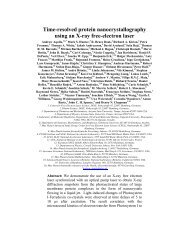
54. Device simulationsTwo <strong>and</strong> three dimensional simulation tools [16-19] are used to optimize the layout <strong>and</strong> the<strong>technology</strong> parameters. Fig.6 shows the simulatedpotential distribution (section A-A in Fig.4) duringthe clear operation.Internal GateSourceClearDrainswitching on the external gate the device current isread out. The drain current response to a given signalcharge defines the amplification <strong>of</strong> the internal gateg q = ♎ I D /♎ q. To analyze the signal response <strong>of</strong> the<strong>DEPFET</strong>, 1600 electron-hole pairs were introducedby a locally <strong>and</strong> temporally limited increase <strong>of</strong> theShockley-Read-Hall generation rate using the twodimensional device simulator TeSCA [16]. Thesimulated signal response, shown in Fig.7,demonstrates an amplification potential <strong>of</strong> more than1nA per electron <strong>for</strong> optimized <strong>DEPFET</strong> structures.Fig.7: Simulated signal response to a signal charge generation <strong>of</strong>1600 electron-hole pairs.Fig.6: Potential distribution <strong>of</strong> a 2x4 array section parallel to thesurface at a depth <strong>of</strong> z=1µm during charge collection simulatedwith Poseidon (VClear = 3V, VBack = -25V, VSource = 0V,VDrain = -5V, VGate = 2V, VClear-Gate = 1V). A single cell ismarked by the dashed line.The simulation illustrates that the electrons canflow unopposed from the internal gate into the clearcontact. The applied clear voltage <strong>of</strong> 20V can bereduced by lowering the potential barrier in the cleargate region. During charge collection, the transistor isswitched <strong>of</strong>f <strong>and</strong> the potential <strong>of</strong> the internal gate canbe adjusted by the voltage <strong>of</strong> the external gate viacapacitive coupling. Fig.6 shows the potential at adepth <strong>of</strong> 1µm, as seen by drifting electrons generatedin the bulk. Note that there is not any attraction <strong>of</strong> then+ clear contact to the electrons at this depth. This isthe result <strong>of</strong> the negative space charge <strong>of</strong> a deepboron doping implanted beneath the clear region. By5. Thinning <strong>technology</strong>The <strong>DEPFET</strong>, as a fully depleted device, needs, inaddition to the front side structures, a p+n diode atthe backside. There<strong>for</strong>e a st<strong>and</strong>ard thinning process isnot applicable because it would destroy the backsidepn – junctions. The key <strong>technology</strong> <strong>of</strong> the processsequence illustrated in Fig.8 is the direct waferbonding [20]. It starts with a sensor wafer on top <strong>and</strong>a h<strong>and</strong>le wafer on bottom, which are bonded togetheron their oxidized surfaces (Fig.8 a). The top wafer,which already contains the backside p+implantations, is thinned to a thickness <strong>of</strong> ~50µm byst<strong>and</strong>ard wafer grinding <strong>and</strong> polishing (Fig.8 b). Thisside is where the actual device is fabricated. Duringthe front side fabrication process, the obtaineds<strong>and</strong>wich package can be h<strong>and</strong>led like a st<strong>and</strong>ard
6wafer without special precautions <strong>for</strong> backsideprotection (Fig.8 c). After topside metallization <strong>and</strong>passivation, the h<strong>and</strong>le wafer is partially etched back(Fig.8 d) leaving a small frame large enough toprovide mechanical stability <strong>and</strong> space <strong>for</strong> the affixedsteering <strong>and</strong> readout chips [5].Fig.9: First results <strong>of</strong> the thinning <strong>technology</strong> development -mechanical samples. The size <strong>of</strong> the upper part is 800x104mm².6. SummaryFig.8 a-d: Joint process sequence <strong>of</strong> wafer thinning <strong>and</strong><strong>DEPFET</strong> production.An inherent advantage <strong>of</strong> this <strong>technology</strong> is thatthe inner silicon oxide acts as a stop layer <strong>for</strong> theetchant, leaving the backside diode <strong>of</strong> the sensorwafer unaffected by the etching. With the proposedconcept, the material budget per layer can be reducedto the range <strong>of</strong> 0.1-0.15% <strong>of</strong> a radiation length,including the already thinned read out <strong>and</strong> line driverchips. Pictures <strong>of</strong> the first mechanical samplesproduced with this <strong>technology</strong> are shown in Fig.9.The <strong>DEPFET</strong> is a promising c<strong>and</strong>idate to fulfillthe challenging detector requirements <strong>of</strong> future highenergy physics experiments, e.g. the TESLA vertexdetector. It <strong>of</strong>fers excellent low noise per<strong>for</strong>mance atroom temperature. Thus the <strong>DEPFET</strong> has thepotential to achieve a good spatial resolution <strong>and</strong> afast readout speed even on a thinned detectorsubstrate. The overall requirement <strong>of</strong> a minimummaterial budget is addressed by an intrinsically lowpower consumption, thereby saving material <strong>for</strong>cooling structures. At the MPI SemiconductorLaboratory, a new MOS based <strong>technology</strong> on 150mmwafer has been developed to produce large detectorarrays.Linearly shaped <strong>DEPFET</strong>s <strong>of</strong> a size <strong>of</strong> about25x25µm² can be made by using two polysiliconlayers. As a detector <strong>pixel</strong> cell consists <strong>of</strong> only onesingle <strong>DEPFET</strong> transistor, it can be produced byrather large lithographic structures with minimumsize <strong>of</strong> 2µm. There<strong>for</strong>e the yield problem occurringespecially in large area detectors is expected to berelaxed. Technology development <strong>and</strong> detectordesign based on two <strong>and</strong> three dimensional processes<strong>and</strong> device simulations demonstrating the operation<strong>and</strong> the technological feasibility <strong>of</strong> <strong>DEPFET</strong> arrays.The first production run has been started. A thinning<strong>technology</strong> based on direct wafer bonding isproposed. Mechanical samples with 50µm thinnedregions were fabricated successfully.
7AcknowledgmentsWe would like to thank K. E. Ehwald <strong>and</strong> B.Heinemann from IHP, Frankfurt/Oder <strong>for</strong> helpfuldiscussions <strong>and</strong> suggestions. The simulation s<strong>of</strong>twarePOSEIDON was developed by A. Castoldi, E. Gatti<strong>and</strong> P. Rehak within the INFN-RIMAX project.References[1] T. Behnke, S. Bertolucci, R.D. Heuer <strong>and</strong> R. Settles, TESLA:The superconducting electron positron linear collider with anintegrated X-ray laser laboratory. Technical design report. Pt4: A detector <strong>for</strong> TESLA’, DESY-01-011.[2] XEUS astrophysics working group, X-ray evolving universespectroscopy – the XEUS science case, ESA, SP-1238 (2000).[3] A <strong>DEPFET</strong> based <strong>pixel</strong> vertex detector <strong>for</strong> the detector atTESLA, LC-DET-2002-004, April 5 th , 2002.[4] J. Kemmer <strong>and</strong> G. Lutz, New semiconductor detectorconcepts, Nucl. Instr. & Meth. A253, 356 (1987).[5] M. Trimpl et al., A fast read out using switched currenttechniques <strong>for</strong> a <strong>DEPFET</strong> <strong>pixel</strong> based vertex detector atTESLA, these proceedings.[6] E. Gatti <strong>and</strong> P. Rehak, Semiconductor drift chamber – Anapplication <strong>of</strong> a novel charge transport scheme, Nucl. Instr. &Meth. A225, 608 (1984).[7] G. Cesura et al, New <strong>pixel</strong> detector concepts based onjunction field effecxt transistors on high resisitivity silicon,Nucl. Instr. & Meth. A377, 521 (1996).[8] J . Ulrici et al., Spectroscopic <strong>and</strong> imaging per<strong>for</strong>mance <strong>of</strong><strong>DEPFET</strong> <strong>pixel</strong> <strong>sensors</strong>, Nucl. Instr. & Meth. A465, 247(2001).[9] P. Klein et al., Study <strong>of</strong> a DEPJFET <strong>pixel</strong> matrix withcontinuos clear mechanism, Nucl. Instr. & Meth. A392, 254(1997).[10] P. Fischer et al., First operation <strong>of</strong> <strong>pixel</strong> imaging matrix basedon <strong>DEPFET</strong> <strong>pixel</strong>s, Nucl. Instr. & Meth. A451, 651 (2000)[11] W. Neeser et al., The <strong>DEPFET</strong> Pixel BIOSCOPE, IEEETrans. Nucl. Sci. 47 No.3 (2000).[12] W. Neeser et al., <strong>DEPFET</strong> a <strong>pixel</strong> device with integratedamplification, Nucl. Instr. & Meth. A477, 129 (2002).[13] G. Lutz, R.H. Richter <strong>and</strong> L.Strüder, Novel Pixel detectors <strong>for</strong>X-ray astronomy <strong>and</strong> other applications, Nucl. Instr. & Meth.A461, 393 (2001).[14] L. Strüder et al., Active <strong>pixel</strong> <strong>sensors</strong> <strong>for</strong> imaging x-rayspectrometers, submitted to SPIE[15] L. Strüder et al., Fully depleted backside illuminatedspectroscopic active <strong>pixel</strong> <strong>sensors</strong> from the infrared to X-rays,Proc. SPIE Conference, Munich 2000, Vol. 4012 (2000).[16] H. Gajewski et al., TeSCA – Two DimensionalSemiconductor Analysis Package, H<strong>and</strong>buch, WIAS, Berlin,1997.[17] ISE TCAD Release 7.0, V0l. 2b, DIOS, 2001.[18] A. Castoldi, E. Gatti <strong>and</strong> P. Rehak, Three-DimensionalAnalytical Solution <strong>of</strong> the Laplace Equation Suitable <strong>for</strong>Semiconductor Detector <strong>Design</strong>, IEEE Trans. on Nucl. Sci.,43, 256-265, (1996).[19] A. Castoldi <strong>and</strong> E. Gatti, Fast tools <strong>for</strong> 3-D design problems insemiconductor detectors, Nucl. Instr. & Meth. A377, 381(1996).[20] Q.-Y. Tong <strong>and</strong> U. Gösele, Semiconductor Wafer Bonding,John Wiley & Sons, Inc., NY, 1999.