X3-0 and X3-5 - Assembly Instructions - Life Fitness
X3-0 and X3-5 - Assembly Instructions - Life Fitness
X3-0 and X3-5 - Assembly Instructions - Life Fitness

You also want an ePaper? Increase the reach of your titles
YUMPU automatically turns print PDFs into web optimized ePapers that Google loves.
Item Qty Description<br />
1<br />
2<br />
3<br />
4<br />
5<br />
6<br />
7<br />
8<br />
9<br />
10<br />
11<br />
12<br />
13<br />
14<br />
15<br />
4<br />
7<br />
2<br />
21<br />
12<br />
2<br />
2<br />
2<br />
2<br />
2<br />
1<br />
6<br />
2<br />
2<br />
4<br />
67 mm Hex Head Bolt<br />
Hex Head Nut<br />
30 mm Hex Head Bolt<br />
16 mm Phillips Screw<br />
8.6 mm Lock Washer<br />
Large Flat Washer<br />
Large Wave Washer<br />
Flat Washer<br />
18.1 mm Lock Washer<br />
20 mm Hex Head Bolt<br />
74 mm Hex Head Bolt<br />
8mmPhillips<br />
Screw<br />
81.5 mm Hex Head Bolt<br />
8 mm Large Phillips Screw<br />
12 mm Phillips Screw<br />
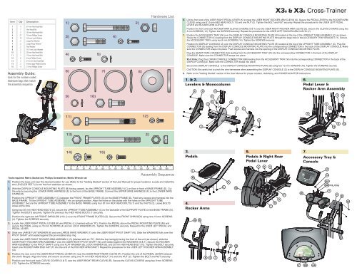
<strong>Assembly</strong> Guide:<br />
Look for the number coded<br />
hardware bags that match<br />
the assembly sequence.<br />
1)<br />
3) 4)<br />
4) 5)<br />
6) 7)<br />
8)<br />
9) 10)<br />
11)<br />
Hardware List<br />
10 20 30 40 50 60 70 80 90 100 110 120 130 140 150 160<br />
<strong>Assembly</strong> Sequence<br />
Tools required: Metric Socket set, Phillips Screwdriver, Metric Wrench set<br />
1. Position the base unit near the desired location for use (Refer to the "Getting Started" section of the User Manual for proper location). Locate <strong>and</strong> install the<br />
two LEVELER FEET (A) into the front stabilizer as shown.<br />
2. With the DISPLAY CONSOLE MOUNTING PLATE (B) facing upward, lay the UPRIGHT TUBE ASSEMBLY (C) on floor in front of BASE FRAME (D). Cut<br />
the wire tie securing the LOWER WIRE HARNESS (E) to the front of the BASE FRAME. Connect the UPPER WIRE HARNESS (F) to the LOWER WIRE<br />
HARNESS.<br />
Position the UPRIGHT TUBE ASSEMBLY (C) between the FRONT FRAME PLATES (G) on the BASE FRAME (D). Feed any excess wire harness into the<br />
BASE FRAME. Tilt the UPRIGHT TUBE ASSEMBLY into an upright position. Align the holes on the plates with the holes on the UPRIGHT TUBE<br />
ASSEMBLY. Secure the UPRIGHT TUBE ASSEMBLY to the BASE FRAME using four 67 mm HEX HEAD BOLTS (1) <strong>and</strong> four NUTS (2). Leave BOLTS<br />
loose at this time.<br />
Using two 30 mm HEX HEAD BOLTS (3), secure the UPRIGHT TUBE ASSEMBLY (C) to the backside of the SUPPORT PLATE on the BASE FRAME (D).<br />
Tighten the BOLTS securely. Tighten the previous four HEX HEAD BOLTS (1) securely.<br />
Position the right <strong>and</strong> left FRONT SHROUDS (H & J) over the FRONT FRAME PLATES (G) . Secure the FRONT SHROUDS using nine 16 mm SCREWS<br />
(4). Tighten the SCREWS securely.<br />
3. Locate the USER RIGHT PEDAL LEVER (K) <strong>and</strong> PEDAL (L) (marked with an “R”). Position the PEDAL above the PEDAL MOUNTING PLATE (M) <strong>and</strong><br />
secure the PEDAL using six 16 mm SCREWS (4) <strong>and</strong> six LOCK WASHERS (5). Tighten the SCREWS securely. Repeat for the USER LEFT PEDAL <strong>and</strong><br />
PEDAL LEVER.<br />
4. Slide one LARGE FLAT WASHER (6) <strong>and</strong> one LARGE WAVE WASHER (7) onto the USER RIGHT PIVOT SHAFT (N). Slide the WASHERS fully over the<br />
PIVOT SHAFT until seated against the pre-installed stop ring.<br />
Locate the USER RIGHT ROCKER ARM ASSEMBLY (O) (Marked with an “R”). With the top h<strong>and</strong>grip facing the front of the unit (as shown), slide the<br />
USER RIGHT ROCKER ARM ASSEMBLY onto the USER RIGHT PIVOT SHAFT (N) until seated against the WASHERS (6 & 7). Secure the ROCKER<br />
ARM ASSEMBLY to the PIVOT SHAFT using one FLAT WASHER (8), LOCK WASHER (9), <strong>and</strong> 20 mm HEX HEAD BOLT (10). Tighten the BOLT securely.<br />
Insert one ROCKER ARM END CAP (P) into the end of the ROCKER ARM SHAFT. Repeat the procedure for the USER LEFT ROCKER ARM ASSEMBLY<br />
(Q).<br />
5. Position the rear end of the USER RIGHT PEDAL LEVER (K) near the USER RIGHT REAR CLEVIS (R). Position the end of the PEDAL LEVER between<br />
the clevis flanges. Align the holes <strong>and</strong> secure as shown using one 74 mm HEX HEAD BOLT (11) <strong>and</strong> one NUT (2). Tighten the BOLT <strong>and</strong> NUT securely.<br />
Position one front <strong>and</strong> back CLEVIS COVER (S & T) over the USER RIGHT REAR CLEVIS (R). Secure the CLEVIS COVERS using two 8 mm SCREWS<br />
(12). Tighten the SCREWS securely.<br />
12)<br />
13) 2)<br />
14) 15)<br />
2)<br />
6.<br />
7.<br />
8.<br />
<strong>X3</strong>0 & <strong>X3</strong>5 Cross-Trainer<br />
Lift the front end of the USER RIGHT PEDAL LEVER (K) to meet the USER RIGHT ROCKER ARM CLEVIS (U). Secure the PEDAL LEVER to the ROCKER ARM<br />
CLEVIS using one 81.5 mm HEX HEAD BOLT (13) <strong>and</strong> one NUT (2). Tighten the BOLT <strong>and</strong> NUT securely. Repeat the procedure for the USER LEFT PEDAL<br />
LEVER <strong>and</strong> ROCKER ARM CLEVIS.<br />
Position the front <strong>and</strong> back ROCKER ARM CLEVIS COVERS (S & T) over the USER RIGHT ROCKER ARM CLEVIS (U). Secure the CLEVIS COVERS using two<br />
8 mm SCREWS (12). Tighten the SCREWS securely. Repeat the procedure for the USER LEFT ROCKER ARM CLEVIS (V).<br />
Position the ACCESSORY TRAY (W) over the DISPLAY CONSOLE MOUNTING PLATE (B) located at the top of the UPRIGHT TUBE ASSEMBLY (C) as shown.<br />
Route the CONNECTOR (X) leading from the DISPLAY CONSOLE MOUNTING PLATE through the large hole in the ACCESSORY TRAY BRACKET (Y). Secure<br />
the ACCESSORY TRAY using two 8 mm SCREWS (14). Tighten the SCREWS securely.<br />
Position the DISPLAY CONSOLE (Z) over the DISPLAY CONSOLE MOUNTING PLATE (B) located at the top of the UPRIGHT TUBE ASSEMBLY (C). Plug the<br />
CONNECTOR (X) leading from the DISPLAY CONSOLE MOUNTING PLATE into the corresponding CONNECTOR in the back of the DISPLAY CONSOLE. Make<br />
sure the CONNECTOR snaps into place. Push excess wire harness into the opening of the DISPLAY CONSOLE MOUNTING PLATE.<br />
Plug the HEART RATE CONNECTOR (AA) leading from the ACCESSORY TRAY (W) into the corresponding CONNECTOR in the back of the DISPLAY<br />
CONSOLE. Make sure the CONNECTOR snaps into place.<br />
<strong>X3</strong>-5 Only: Plug the LOWER CONSOLE CONNECTOR (BB) leading from the ACCESSORY TRAY (W) into the corresponding CONNECTOR in the back of the<br />
DISPLAY CONSOLE. Make sure the CONNECTOR snaps into place.<br />
Secure the DISPLAY CONSOLE to the DISPLAY CONSOLE MOUNTING PLATE (B) using four 12 mm SCREWS (15). Tighten the SCREWS securely.<br />
CAUTION: Be careful not to pinch the wire harnesses when assembling the DISPLAY CONSOLE (Z) to the DISPLAY CONSOLE MOUNTING PLATE (B).<br />
Refer to the "Getting Started" section of the User Manual for proper location, stabilizing, <strong>and</strong> POWER ADAPTER instructions.<br />
1.&2. 6.<br />
Levelers & Monocolumn<br />
Pedal Lever &<br />
Rocker Arm <strong>Assembly</strong><br />
3.<br />
Pedals<br />
L<br />
M<br />
4 H C<br />
4.<br />
Rocker Arms<br />
Q<br />
B<br />
3<br />
2<br />
F<br />
E<br />
N 6 7<br />
O<br />
4<br />
K<br />
A<br />
G<br />
1<br />
8 10<br />
9 P<br />
12<br />
J<br />
4<br />
5.<br />
Pedals & Right Rear<br />
Pedal Lever<br />
2 K<br />
V<br />
T<br />
R<br />
S<br />
11<br />
W<br />
7.<br />
V<br />
Accessory Tray &<br />
Console<br />
X BB AA<br />
2<br />
Z<br />
14<br />
AA<br />
BB<br />
U<br />
Y<br />
12<br />
<strong>X3</strong> Only<br />
5<br />
T 12<br />
X<br />
S 13<br />
B<br />
15
© 2005 <strong>Life</strong> <strong>Fitness</strong>, a division of Brunswick Corporation. All rights reserved. <strong>Life</strong> <strong>Fitness</strong> is a registered trademarks of Brunswick<br />
Corporation. Any use of this trademark, without the express written consent of <strong>Life</strong> <strong>Fitness</strong> is forbidden. 7954201 Rev A (06/05)<br />
5100 N. RIVER ROAD, SCHILLER PARK, ILLINOIS 60176<br />
LIFEFITNESS.COM<br />
<strong>Life</strong> <strong>Fitness</strong> offers a full line of premier fitness equipment for the home.<br />
TOTAL-BODY ELLIPTICAL CROSS-TRAINERS | TREADMILLS | LIFECYCLE EXERCISE BIKES<br />
STAIRCLIMBERS | GYM SYSTEMS<br />
®<br />
0 5 Cross-Trainer<br />
<strong>X3</strong> & <strong>X3</strong><br />
ASSEMBLY<br />
INSTRUCTIONS