G7 CABLE MOTION⢠GYM SYSTEM - Life Fitness
G7 CABLE MOTION⢠GYM SYSTEM - Life Fitness
G7 CABLE MOTION⢠GYM SYSTEM - Life Fitness

Create successful ePaper yourself
Turn your PDF publications into a flip-book with our unique Google optimized e-Paper software.
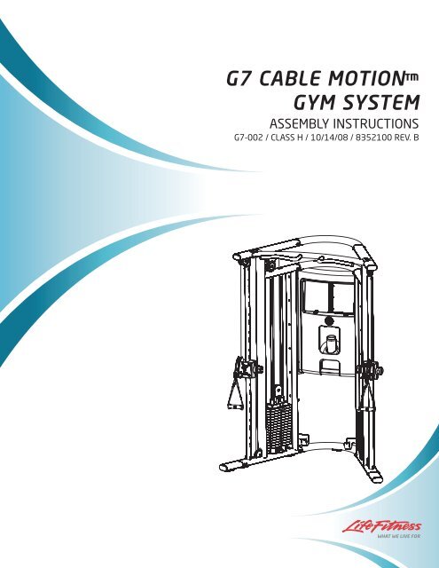
<strong>G7</strong> <strong>CABLE</strong> MOTION<br />
<strong>GYM</strong> <strong>SYSTEM</strong><br />
ASSEMBLY INSTRUCTIONS<br />
<strong>G7</strong>-002 / CLASS H / 10/14/08 / 8352100 REV. B
TABLE OF CONTENTS<br />
Safety Statement . . . . . . . . . . . . . . . .2 Required Hardware . . . . . . . . . . . . . . . .8<br />
<strong>G7</strong> Warning Labels . . . . . . . . . . . . . . .4 Assembly Instructions . . . . . . . . . . . . . .10<br />
Gym Dimensions. . . . . . . . . . . . . . . . .5 General Maintenance . . . . . . . . . . . . . .24<br />
<strong>G7</strong> Live Area . . . . . . . . . . . . . . . . . . .6 Warranty Statement . . . . . . . . . . . . . . .25<br />
Components List . . . . . . . . . . . . . . . . .7 Contact Information . . . . . . . . . . . . . . .26<br />
SAFETY INFORMATION<br />
It is the sole responsibility of the purchaser of LIFE FITNESS products to read the owner's manual, warning labels and<br />
instruct all individuals, whether they are the end user or supervising personnel on proper usage of the equipment.<br />
UNDERSTANDING EACH AND EVERY WARNING TO THE FULLEST IS IMPORTANT. IF ANY OF THESE INSTRUC-<br />
TIONS OR WARNINGS ARE UNCLEAR, CONTACT LIFE FITNESS CUSTOMER SERVICE IMMEDIATELY AT 1-800-<br />
351-3737 WITHIN THE US AND CANADA. INTERNATIONAL OFFICE CONTACT INFORMATION IS AVAILABLE ON<br />
PAGE 26.<br />
Keep children away from strength equipment. Parent or others supervising children must provide close supervision of<br />
children if the equipment is used in the presence of children.<br />
This equipment is categorized as class H per EN 957-1. And as such this equipment is only intended for Home use. It is<br />
not intended for commercial, institutional and/or studio facilities use. Contact LIFE FITNESS with any questions regarding<br />
this classification.<br />
It is recommended that all users of LIFE FITNESS exercise equipment be informed of the following information prior to<br />
use.<br />
ACCESS CONTROL<br />
LIFE FITNESS recommends that all fitness equipment be used in a supervised area. It is recommended that<br />
the equipment be located in an access controlled area. Control is the responsibility of the facility owner.<br />
INSTALLATION<br />
SECURING EQUIPMENT - LIFE FITNESS recommends that all equipment be secured to a solid, level<br />
surface to stabilize and eliminate rocking or tipping over. This must be per formed by a licensed contractor.<br />
PROPER USAGE<br />
1. Do not use any equipment in any way other than as designed or intended by the manufacturer. It is<br />
imperative that LIFE FITNESS equipment is used properly to avoid injury.<br />
2. Injuries may result if exercising improperly or excessively. It is recommended that all individuals consult a<br />
physician prior to commencing an exercise program. If at any time during exercise you feel faint, dizzy or<br />
experience pain, STOP EXERCIZING and consult your physician.<br />
3. Keep body parts (hands, feet, hair, etc.), clothing and jewelry away from moving parts to avoid injury.<br />
4. When adjusting any seat, knee hold down pad, range of motion limiter, foothold pad, pulley or any other<br />
type of adjuster, make certain that the adjusting pin is fully engaged in the hole to avoid injury.<br />
2
INSPECTION<br />
1. DO NOT use or permit use of any equipment that is damaged and or has worn or broken parts. For all<br />
LIFE FITNESS equipment use only replacement parts supplied by LIFE FITNESS.<br />
2. Cables and Belts pose an extreme liability if used when frayed. Always replace any cable at first sign of<br />
wear (consult LIFE FITNESS if uncertain).<br />
3. Routinely inspect all accessory clips that join attachments to the cables and replace at the first sign of<br />
wear.<br />
4. MAINTAIN LABELS AND NAMEPLATES - Do not remove labels for any reason. They contain important<br />
information. If unreadable or missing, contact LIFE FITNESS for a replacement.<br />
5. EQUIPMENT MAINTENANCE - Preventative maintenance is the key to smooth operating equipment as<br />
well as keeping your liability to a minimum. Equipment needs to be inspected at regular intervals.<br />
6. Ensure that any person(s) making adjustments or performing maintenance or repair of any kind is<br />
qualified to do so. LIFE FITNESS will provide service and maintenance training at our corporate facility<br />
upon request or in the field if proper arrangements are made.<br />
7. Before any use, examine all accessories approved for use with the LIFE FITNESS equipment for<br />
damage or wear.<br />
8. DO NOT ATTEMPT TO USE OR REPAIR ANY ACCESSORY APPROVED FOR USE WITH THE LIFE<br />
FITNESS EQUIPMENT WHICH APPEARS TO BE DAMAGED OR WORN.<br />
OPERATING WARNINGS<br />
1. It is the purchaser's sole responsibility to properly instruct its end users and supervising personnel as to<br />
the proper operating procedures of all LIFE FITNESS equipment.<br />
2. Keep children away from strength equipment. Parent or others supervising children must provide close<br />
supervision of children if the equipment is used in the presence of children.<br />
3. Do not allow users to wear loose fitting clothing or jewelry while using equipment. It is also<br />
recommended to have user's secure long hair back and up to avoid contact with moving parts.<br />
4. All bystanders must stay clear of all users, moving parts and attached accessories and components<br />
while machine is in operation.<br />
SELECTORIZED WEIGHT STACK <strong>SYSTEM</strong>S<br />
1. Use only weight selector pins supplied by LIFE FITNESS on weight stacks. Substitutes are forbidden.<br />
2. Fully insert weight selector pins. Partial insertion can cause weights to fall unexpectedly.<br />
3. Never pin the weight stack in an elevated position.<br />
4. Never remove selector pin if any weights are suspended.<br />
5. Never attempt to release jammed weights or parts.<br />
6. Never use dumbbells or other means to incrementally increase the weight resistance. Use only those<br />
means provided by LIFE FITNESS.<br />
3
<strong>G7</strong> WARNING LABELS<br />
NOTE: Lock the weight stack when not using the gym. Make sure all the weight plates are resting on the plate below<br />
with no gap in between. Insert the weight selector pin in the tab underneath the weight stack. The weight selector pin<br />
should be inserted until the knob touches the metal tab. Once the pin goes through the weight stack system, the weight<br />
stack becomes immobile. Verify that the pin has gone through the weight stack stem.<br />
4<br />
Schiller Park, IL www.lifefitness.com<br />
Model: FZCP-<br />
Serial Number:<br />
Class: S - Studio<br />
Maximum User Weight: 300 lbs (136kg)
Weight: 720 lbs<br />
Resistance Ratio: 1:2<br />
Weight Stack: 160 lbs<br />
<strong>GYM</strong> DIMENSIONS<br />
5
10’<br />
<strong>G7</strong> LIVE AREA<br />
18’-8”<br />
NOTE: The live area shows the extent of the <strong>G7</strong> gym. It does not include the user.<br />
6<br />
12”<br />
12”
ITEM NO. QTY. DESCRIPTION<br />
1 1 LEFT TOWER<br />
2 1 TOP BRACKET TUBE<br />
3 1 MIDDLE BRACKET TUBE<br />
4 1 BOTTOM BRACKET TUBE<br />
COMPONENTS LIST<br />
5 1 LEFT SLIDE TUBE (WITH ROLLER CARRIAGE) ASSEMBLY<br />
6 1 RIGHT U BRACKET<br />
7 1 LEFT U BRACKET<br />
8 1 RIGHT SWIVEL PULLEY<br />
9 1 LEFT SWIVEL PULLEY<br />
10 1 RIGHT SLIDE TUBE (WITH ROLLER CARRIAGE) ASSEMBLY<br />
11 1 RIGHT TOWER<br />
12 1 CHIN UP BAR<br />
13 16 PULLEY<br />
14 4 PARTIAL PULLEY COVER<br />
15 4 GUIDE ROD RETAINER<br />
16 4 GUIDE ROD ASSEMBLY<br />
17 30 10 LB WEIGHT PLATE<br />
18 2 TOP PLATE<br />
19 2 HEAD PLATE PULLEY ASSEMBLY<br />
20 4 WEIGHT STACK CUSHION<br />
21 2 <strong>CABLE</strong><br />
22 2 FOOT EXTENSION<br />
23 2 SIDE SHROUD<br />
24 6 KIOSK BRACKET<br />
25 1 KIOSK ASSEMBLY<br />
26 2 WEIGHT PIN & RING<br />
27 4 FULL PULLEY COVER<br />
28 1 LEFT ROLLER CARRIAGE<br />
29 1 RIGHT ROLLER CARRIAGE<br />
30 2 D RINGS<br />
31 1 THIGH STRAP<br />
32 1 FOOT STRAP<br />
33 1 TOWEL<br />
34 1 MARKER<br />
35 2 HANDLES<br />
36 2 SNAP LINKS<br />
37 1 DVD<br />
38 1 TOUCH-UP PAINT<br />
39 1 EXERCISE BALL<br />
40 1 PUMP<br />
41 1 LONG BAR<br />
42 1 WATER BOTTLE<br />
60 1 EXERCISE BOOKLET<br />
7
HARDWARE<br />
ITEM NO. QTY. DESCRIPTION<br />
43 32 M10 X 20MM SCREW<br />
44 58 M10 WASHER<br />
45 20 M5 HEX SCREW<br />
46 20 M6 WASHER<br />
47 4 M10 X 55MM SCREW<br />
48 2 M10 X 45MM SCREW<br />
49 13 M10 HEX NYLOCK NUT<br />
50 7 M10 X 70MM SCREW<br />
51 2 M10 SOCKET HEAD NUT<br />
52 2 M10 X 50MM SCREW<br />
53 2 PULLEY RETAINER<br />
54 4 RETAINER RING<br />
COMPONENTS LIST<br />
55 4 M10 X 50MM HEX TENSION SCREW<br />
56 32 M5 SHOULDER SCREW<br />
57 12 M10 X 16MM SCREW<br />
58 12 M10.5 WASHER<br />
59 2 .500-13 JAM NUT<br />
BLISTER PACKS<br />
Blister Pack 7-1 1<br />
Blister Pack 7-2 1<br />
Blister Pack 7-3 1<br />
Blister Pack 7-4 1<br />
Blister Pack 7-5 1<br />
Blister Pack 7-6 1<br />
REQUIRED TOOLS<br />
ADJUSTABLE WRENCH<br />
EXTERNAL SNAP RING PLIERS<br />
PHILLIPS SCREW DRIVER<br />
ALLEN WRENCHES (4mm, 5mm, 7mm)<br />
WRENCH (17mm)<br />
8
M10 X 20MM SCREW (#43)<br />
M6 WASHER (#46)<br />
PULLEY RETAINER (#53)<br />
M5 SHOULDER SCREW (#56)<br />
M6 JAM NUT (#59)<br />
M10 X 45MM SCREW (#48)<br />
HARDWARE:<br />
M10 WASHER (#44)<br />
RETAINER RING (#54)<br />
M10 X 55MM SCREW (#47)<br />
M10 HEX NYLOCK NUT (#49)<br />
M10.5 WASHER (#58)<br />
9<br />
M5 HEX SCREW (#45)<br />
M10 SOCKET NUT (#51)<br />
M10 X 70MM SCREW (#50) M10 X 50MM SCREW (#52)<br />
Centimeters<br />
M10 X 50MM HEX TENSION SCREW (#55)<br />
M10 X 16MM SCREW (#57)
A<br />
1<br />
B<br />
NOTE: Two person assembly is recommended.<br />
STEP 1:<br />
Use the following hardware contained in Blister Pack (7-1):<br />
� M10 x 20mm SCREW (Qty. 24)<br />
� M10 WASHER (Qty. 24)<br />
11<br />
1<br />
� Make sure the LEFT TOWER (1) and the RIGHT TOWER (11) are positioned correctly prior to assembly. The LEFT<br />
U BRACKET (A) and RIGHT U BRACKET (B) should point towards each other as shown in the above illustration.<br />
� Use four M10 x 20mm SCREWS (43) and four M10 WASHERS (44) to connect the BOTTOM BRACKET TUBE (4)<br />
to the LEFT TOWER (1). Finger tighten only.<br />
NOTE: THE BOTTOM BRACKET TUBE (4) HAS A RUBBER PAD ATTACHED TO IT TO MAKE CONTACT WITH THE<br />
FLOOR.<br />
10<br />
43<br />
43<br />
44<br />
44<br />
2<br />
44 43<br />
44 43<br />
� Repeat the above process using the TOP BRACKET TUBE (2) and the MIDDLE BRACKET TUBE (3).<br />
NOTE: THE TOP BRACKET TUBE (2) DOES NOT HAVE ANY HOLES. THE MIDDLE BRACKET TUBE (3) HAS<br />
THREE HOLES THROUGH THE TOP AND BOTTOM.<br />
� Repeat all of the above steps to attach the TOP (2), MIDDLE (3), and BOTTOM (4) BRACKET TUBES to the RIGHT<br />
TOWER (11).<br />
4<br />
3<br />
11
STEP 2:<br />
Use the following hardware contained in Blister Pack (7-1):<br />
� M10 x 70mm SCREW (Qty. 4)<br />
� M10 WASHER (Qty. 8)<br />
� M10 HEX NYLOCK NUT (Qty. 4)<br />
50<br />
44<br />
1<br />
44<br />
49<br />
� Attach the CHIN UP BAR (12) between the LEFT TOWER (1) and RIGHT TOWER (11) using four M10 x 70mm<br />
SCREWS (50), eight M10 WASHERS (44), and four M10 HEX NYLOCK NUTS (49). Finger tighten only.<br />
NOTE: Make sure the CHIN UP BAR (12) is in the correct position as shown.<br />
� Tighten all FRAME and CHIN UP BAR screws and nuts securely.<br />
11<br />
12<br />
50<br />
44<br />
11
STEP 3:<br />
28<br />
5<br />
Use the following hardware contained in Blister Pack (7-2):<br />
� M10 x 45mm SCREW (Qty. 2)<br />
� M10 WASHER (Qty. 8)<br />
� M10 HEX NYLOCK NUT (Qty. 4)<br />
� M10 x 55mm SCREW (Qty. 2)<br />
49<br />
44<br />
49<br />
C<br />
44<br />
44<br />
48<br />
1<br />
D<br />
44<br />
47<br />
� Slide the top of the LEFT SLIDE TUBE ASSEMBLY (5) over the UPPER BRACKET (C) on the LEFT TOWER (1).<br />
NOTE: MAKE SURE THE ENGRAVED NUMBERS ON THE LEFT SLIDE TUBE ASSEMBLY (5) FACE THE INSIDE<br />
OF THE <strong>GYM</strong>. NOTE THE ORIENTATION OF THE CARRIAGE.<br />
� Secure the LEFT SLIDE TUBE ASSEMBLY (5) to the UPPER BRACKET (C) of the LEFT TOWER (1) using one<br />
M10 x 45mm SCREW (48), two M10 WASHERS (44), and one M10 HEX NYLOCK NUT (49). Do not tighten at<br />
this time.<br />
� Secure the LEFT SLIDE TUBE ASSEMBLY (5) to the LOWER BRACKET (D) of the LEFT TOWER (1) using one<br />
M10 x 55mm SCREW (47), two M10 WASHERS (44), and one M10 HEX NYLOCK NUT (49).<br />
� Repeat the above process to secure the RIGHT SLIDE TUBE ASSEMBLY (10) to the RIGHT TOWER (11). Tighten<br />
all nuts and screws securely.<br />
12<br />
29<br />
10<br />
11
STEP 4:<br />
1<br />
Use the following hardware contained in Blister Pack (7-2):<br />
� M5 SHOULDER SCREW (Qty. 32)<br />
� M5 HEX SCREW (Qty. 8)<br />
� M6 WASHER (Qty. 8)<br />
F<br />
6<br />
7<br />
45<br />
� Remove the protective paper from the SIDE SHROUD (23) before installation.<br />
� Install one SIDE SHROUD (23) to the RIGHT TOWER (11) using sixteen M5 SHOULDER SCREWS (56) on the<br />
inside of the SIDE SHROUD (23) into the UPRIGHT TUBES (E) of the RIGHT TOWER (11). Tighten the screws<br />
securely.<br />
NOTE: YOU MUST BE STANDING INSIDE THE <strong>GYM</strong> TO INSTALL THE SIDE SHROUD (23).<br />
� Repeat this process for installing one SIDE SHROUD (23) to the LEFT TOWER (1).<br />
46<br />
E<br />
� Attach the RIGHT U BRACKET (6) onto the back of the UPRIGHT TUBE (E) of the RIGHT TOWER (11) using four<br />
M5 HEX SCREWS (45) and four M6 WASHERS (46). Tighten the screws securely.<br />
� Repeat this process for installing the LEFT U BRACKET (7) onto the back of the UPRIGHT TUBE (F) of the LEFT<br />
TOWER (1).<br />
13<br />
11<br />
56<br />
23
STEP 5:<br />
Use the following hardware contained in Blister Pack (7-3):<br />
� M10 x 50mm HEX TENSION SCREW (Qty. 4)<br />
� GUIDE ROD RETAINER (Qty. 4)<br />
� RETAINER RING (Qty. 4)<br />
NOTE: INSTALL FROM THE INSIDE OF THE UNIT.<br />
11<br />
G<br />
� Position two WEIGHT STACK CUSHIONS (20) and GUIDE RODS (16) at the GUIDE ROD BRACKET (G) on the<br />
RIGHT TOWER (11) as shown.<br />
NOTE: MAKE SURE THAT THE PLUGGED END OF THE GUIDE RODS (16) ARE FACING UP.<br />
� Slide one WEIGHT PLATE (17) over the GUIDE RODS (16) and slowly lower the WEIGHT PLATE (17) onto the<br />
WEIGHT STACK CUSHIONS (20).<br />
� Continue stacking a total of fifteen WEIGHT PLATES (17).<br />
� Slide one TOP PLATE (18) over the GUIDE RODS (16) and slowly lower it onto the WEIGHT PLATES (17).<br />
� Slide one WEIGHT PIN with RING (26) over the stem of the TOP PLATE (18).<br />
� Thread the HEAD PLATE PULLEY ASSEMBLY (19) into the TOP PLATE (18). Do not tighten! This will be adjusted<br />
later. Make sure the JAM NUT (59) is threaded onto the HEAD PLATE PULLEY ASSEMBLY (19) before threading<br />
into the TOP PLATE (18).<br />
� Slide one RETAINER RING (54) over each of the GUIDE RODS (16).<br />
� Thread an M10 x 50mm HEX TENSION SCREW (55) into each of the two GUIDE ROD RETAINERS (15). Do not<br />
fully thread the M10 x 50mm HEX TENSION SCREWS (55) into the GUIDE ROD RETAINERS (15).<br />
� Slide the GUIDE ROD RETAINERS (15) into the holes on the RIGHT TOWER (11). Make sure the M10 x 50mm<br />
HEX TENSION SCREWS (55) in the GUIDE ROD RETAINERS (15) are facing up.<br />
� Push the GUIDE ROD RETAINERS (15) up high enough so that the GUIDE RODS (16) can be placed under<br />
them.<br />
� Lower the GUIDE ROD RETAINERS (15) over the GUIDE RODS (16).<br />
� Slide the RETAINER RINGS (54) up. Use a RETAINING RING PLIER to secure the RETAINER RINGS (54) into<br />
the groove on the GUIDE ROD RETAINERS (15). If the groove is hidden inside the hole on the tube, use a 5mm<br />
ALLEN WRENCH to loosen the M10 x 50mm HEX TENSION SCREW (55) until the groove is accessible.<br />
� Repeat this step to complete the LEFT TOWER assembly.<br />
14<br />
54<br />
16<br />
55<br />
15<br />
20<br />
19<br />
26<br />
18<br />
17<br />
59<br />
NOTE: The Side Shroud is not shown in<br />
this illustration for clarity.
STEP 6:<br />
� Uncoil the cables to remove all twists.<br />
48<br />
44<br />
13<br />
Lower Pulley<br />
44<br />
49<br />
51<br />
� Remove the (UPPER) PULLEYS (13) on the RIGHT TOWER (11) and LEFT TOWER (1) by removing the M10 x<br />
50mm SCREW (52), PULLEY RETAINER (53), M10 SOCKET HEAD NUT (51), and PARTIAL PULLEY COVERS<br />
(14). Set the (UPPER) PULLEYS (13) and hardware aside.<br />
� Remove the (LOWER) PULLEYS (13) on the RIGHT TOWER (11) and LEFT TOWER (1) by removing the M10 x<br />
45mm SCREW (48), two M10 WASHERS (44), and M10 HEX NYLOCK NUT (49).<br />
15<br />
14<br />
13<br />
Upper Pulley<br />
14<br />
53<br />
52
13<br />
Upper Pulley<br />
21<br />
29<br />
19<br />
13<br />
Lower Pulley<br />
STEP 7:<br />
Use the following hardware contained in Blister Packs (7-3), (7-4) and (7-5):<br />
� M10 WASHER (Qty. 4)<br />
� M10 HEX NYLOCK NUT (Qty. 2)<br />
� M10 x 45mm SCREW (Qty. 2)<br />
� M10 SOCKET HEAD NUT (Qty. 2)<br />
� M10 x 50mm SCREW (Qty. 2)<br />
� PULLEY RETAINER (Qty. 2)<br />
13<br />
59<br />
Middle Upper Pulley<br />
� Remove the JAM NUT (59) from the threaded end of the <strong>CABLE</strong> (21).<br />
� Lower the threaded end of the <strong>CABLE</strong> (21) down the long vertical tube that is in front of the gym until it can be retrieved near<br />
where the (LOWER) PULLEY (13) was located. Carefully pull enough cable out to reach the RIGHT ROLLER CARRIAGE (29).<br />
� INSTALL the (LOWER) PULLEY (13) using the M10 x 45mm SCREW (48), two M10 WASHERS (44), and M10 HEX NYLOCK<br />
NUT (49). Be sure that the <strong>CABLE</strong> (21) is properly routed around the (LOWER) PULLEY (13).<br />
� Bring the threaded end of the <strong>CABLE</strong> (21) up to the RIGHT ROLLER CARRIAGE (29) and thread the <strong>CABLE</strong> (21) into the<br />
RIGHT ROLLER CARRIAGE (29). Do not tighten!<br />
� Assemble the (MIDDLE UPPER) PULLEY (13) by using two FULL PULLEY COVERS (14), one PULLEY RETAINER (53), one<br />
M10 SOCKET HEAD NUT (51) and one M10 x 50mm SCREW (52).<br />
� Feed the cable end with the small ball between the MIDDLE UPPER PULLEY BRACKET (H) and then through the forward most<br />
hole in the MIDDLE BRACKET TUBE (3) above the HEAD PLATE PULLEY ASSEMBLY (19).<br />
� Take the <strong>CABLE</strong> (21) down and around the HEAD PLATE PULLEY (19) and back up through the MIDDLE BRACKET TUBE (3)<br />
again, passing through the remaining access hole.<br />
� Feed the <strong>CABLE</strong> (21) around where the (UPPER) PULLEY (13) of the RIGHT TOWER (11) was located. Forward the <strong>CABLE</strong><br />
(21) through the TOP BRACKET TUBE (2) and out the access hole where the (UPPER) PULLEY (13) was located.<br />
� REINSTALL the (UPPER) PULLEY (13) using the previously removed M10 x 50mm SCREW (I), PULLEY RETAINER (J), M10<br />
SOCKET HEAD NUT (K), and PARTIAL PULLEY COVER (L). Be sure that the <strong>CABLE</strong> (21) is properly routed around the PUL-<br />
LEY.<br />
� Bring the <strong>CABLE</strong> (21) down to the RIGHT ROLLER CARRIAGE (29).<br />
� Feed the <strong>CABLE</strong> (21) through the two pulleys in the RIGHT ROLLER CARRIAGE (29) as shown.<br />
� Repeat Step 6 to route the cable through the LEFT TOWER (1).<br />
2<br />
3<br />
16<br />
51<br />
51<br />
14<br />
27<br />
H<br />
13<br />
Upper Pulley<br />
Middle Upper Pulley<br />
13<br />
27<br />
53<br />
14<br />
38<br />
53<br />
52
STEP 8:<br />
Slide Mechanism to insert<br />
or Exchange Handles<br />
I<br />
17<br />
ITEM QTY DESCRIPTION<br />
I 1 QUICK CONNECT COUPLER<br />
J 1 QUICK CONNECT HOUSING<br />
K 1 QUICK CONNECT SLEEVE<br />
L 1 QUICK CONNECT SPRING<br />
M 2 M5 HEX SCREW<br />
K<br />
Cable<br />
� Dissemble one QUICK CONNECT by removing the two M5 HEX SCREWS (M) from the QUICK CONNECT COU-<br />
PLER (I). Carefully remove the QUICK CONNECT SPRING (L), the QUICK CONNECT SLEEVE (K) and the QUICK<br />
CONNECT HOUSING (J).<br />
� Slide the QUICK CONNECT HOUSING (J), QUICK CONNECT SPRING (L), and QUICK CONNECT SLEEVE (K)<br />
onto the cable as shown. Insert the cable end into the QUICK CONNECT COUPLER (I).<br />
� Slide the entire assembly over the QUICK CONNECT COUPLER (I). Attach the QUICK CONNECT COUPLER (I) and<br />
QUICK CONNECT HOUSING (J) together. Use the two M5 HEX SCREWS (M) to tighten.<br />
NOTE: IF NECESSARY, ENSURE <strong>CABLE</strong>S ARE PROPER LENGTH; MAKE NECESSARY ADJUSTMENTS TO THE<br />
WEIGHT STACK PULLEY (TIGHTEN OR LOOSEN); THREAD THE END OF THE <strong>CABLE</strong>; AND REMOVE THE PUL-<br />
LEY FROM THE HOUSING AND SPIN CLOCKWISE OR COUNTER CLOCKWISE TO LOOSEN/TIGHTEN.<br />
L<br />
K<br />
J<br />
M
STEP 9:<br />
28<br />
19<br />
18<br />
21<br />
� Make adjustments to the HEAD PLATE PULLEY (19) and the threaded cable end to adjust cable length and to<br />
ensure the cable is taut.<br />
� If the threaded cable end is completely threaded into the LEFT ROLLER CARRIAGE (28) and there is still some<br />
slack in the <strong>CABLE</strong> (21), remove the pulley from the HEAD PLATE PULLEY (19). Thread the HEAD PLATE PULLEY<br />
(19) further into the TOP PLATE ASSEMBLY (18) and reinstall the pulley.<br />
� Once the <strong>CABLE</strong> (21) is taut, engage the jam nut at the threaded end of the cable as well as at the HEAD PLATE<br />
PULLEY ASSEMBLY (19).<br />
18
STEP 10:<br />
22<br />
Use the following hardware contained in Blister Pack (7-4):<br />
� M10 x 20mm SCREW (Qty. 8)<br />
� M10 WASHER (Qty. 8)<br />
43<br />
44<br />
44<br />
43<br />
� Install one FOOT EXTENSION (22) to the bottom of the LEFT TOWER (1) using four M10 x 20mm SCREWS (43)<br />
and four M10 WASHERS (44).<br />
� Repeat the above step to attach the other FOOT EXTENSION (22) to the bottom of the RIGHT TOWER (11).<br />
19<br />
1
STEP 11:<br />
Use the following hardware contained in Blister Pack (7-6):<br />
� M5 HEX SCREW (Qty. 12)<br />
� M6 WASHER (Qty. 12)<br />
� M10 x 16mm SCREW (Qty. 12)<br />
� M10.5 WASHER (Qty. 12)<br />
� M10 x 70mm SCREW (Qty. 3)<br />
� M10 WASHER (Qty. 6)<br />
� M10 HEX NYLOCK NUT (Qty. 3)<br />
3<br />
25<br />
50<br />
44<br />
44<br />
49<br />
20<br />
46<br />
11<br />
24<br />
3<br />
45 58<br />
� Attach the six KIOSK BRACKETS (24) to the RIGHT TOWER (11) and LEFT TOWER (1) using two M5 HEX<br />
SCREWS (45) and two M6 WASHERS (46) each. Tighten the screws securely.<br />
� Fasten the KIOSK (25) to the KIOSK BRACKETS (24) using twelve M10 x 16mm SCREWS (57) and twelve M10.5<br />
WASHERS (58).<br />
NOTE: SUPPORT THE KIOSK (25) UNTIL THE SCREWS ARE INSTALLED.<br />
� Secure the top of the KIOSK (25) to the MIDDLE BRACKET TUBE (3) using three M10 x 70mm SCREWS (50), six<br />
M10 WASHERS (44), and three M10 HEX NYLOCK NUTS (49).<br />
NOTE: THE TOP OF THE KIOSK (25) HAS THREE SLOTS THAT FIT UNDERNEATH THE THREE HOLES OF THE<br />
MIDDLE BRACKET TUBE (3).<br />
25<br />
57
STEP 12:<br />
N<br />
� Adjust the rollers if the ROLLER CARRIAGE (28) rolls up and down the tube with difficulty, or if it seems to sloppy.<br />
� Unscrew the cable end from the roller carriage housing.<br />
� Remove the SCREWS (N) that hold the two PLASTIC COVERS (O) together.<br />
O<br />
� There are two ROLLER ADJUSTMENT SCREWS (P), each with a spring, on the back side of the roller carriage<br />
housing. The roller drag can be increased/decreased by adjusting these screws.<br />
21<br />
28<br />
O<br />
P
31<br />
STEP 13:<br />
39<br />
32<br />
36 35<br />
41<br />
� The <strong>G7</strong> comes with the following accessories: THIGH STRAP (31), FOOT STRAP (32), HANDLES (35), SNAP<br />
LINKS (36), LONG BAR (41), and EXERCISE BALL (39).<br />
22
STEP 14:<br />
� Use the FRONT HANDLE (Q) to tilt the bench.<br />
� Steer the bench to align with the U BRACKETS (R).<br />
� Insert one PIN (S) into each bracket so the bench is restrained.<br />
Q<br />
23<br />
R<br />
S
Please note:<br />
MAINTENANCE<br />
* We recommend cleaning your product (pads and frame) on a regular basis, using<br />
warm soapy water. Touch-up paint can be purchased from your <strong>Life</strong> <strong>Fitness</strong> customer<br />
service representative at (800) 351-3737.<br />
* Inspect equipment before each use. Tighten all loose connections are replace worn<br />
parts immediately. Failure to do so may result in serious injury.<br />
* PLEASE RECORD THE INFORMATION REQUESTED BELOW. IN THE EVENT<br />
YOU MAY NEED SERVICE YOU WILL BE ASKED FOR THIS INFORMATION.<br />
REMEMBER TO FILL OUT YOUR WARRANTY REGISTRATION CARD ON-LINE<br />
AT WWW.LIFEFITNESS.COM.<br />
Model #: _____________________________________<br />
Serial #'s: _____________________________________<br />
(Note: The Model/Serial label is located on the back side of the UPRIGHT TUBE of the LEFT TOWER)<br />
Date of Purchase: _____________________________________<br />
Dealer’s Name _____________________________________<br />
Dealer’s Phone# _____________________________________<br />
Thank you for purchasing the <strong>Life</strong> <strong>Fitness</strong><br />
<strong>G7</strong> <strong>CABLE</strong> MOTION <strong>GYM</strong> <strong>SYSTEM</strong><br />
24
LIMITED WARRANTY<br />
<strong>Life</strong> <strong>Fitness</strong>® <strong>G7</strong> Cable Motion Gym System<br />
<strong>Life</strong> <strong>Fitness</strong> extends the following LIMITED WARRANTY to the original owner (proof of purchase required, keep your<br />
receipt with this manual) of the <strong>Life</strong> <strong>Fitness</strong> product. The Warranty terms apply to IN HOME and LIGHT INSTITUTIONAL<br />
USE ONLY.<br />
1. LIMITED WARRANTY ON FRAME AND WELDS. If the frame of the <strong>Life</strong> <strong>Fitness</strong> product or a weld should crack<br />
or break, it will be repaired or replaced by <strong>Life</strong> <strong>Fitness</strong>. Terms: IN HOME USE ONLY: <strong>Life</strong>time – for so long as the<br />
Customer owns the <strong>Life</strong> <strong>Fitness</strong> product; LIGHT INSTITUTIONAL USE: Ten (10) years.<br />
2. LIMITED WARRANTY ON PARTS. If the following parts are defective in material or workmanship, <strong>Life</strong> <strong>Fitness</strong> will<br />
supply replacement parts: all bolts, nuts, washers, bearings, bushings, pulleys, thumbscrews, collars, cable retaining<br />
clips, adjustable pre-stretch slides, roller pad shafts, allen head bolts, weight selector pin, weight stack shaft,<br />
set screws, protector caps, adjustment chain, cotter pin, plunger, spring and knob. Terms: IN HOME USE ONLY:<br />
<strong>Life</strong>time – for so long as the Customer owns the <strong>Life</strong> <strong>Fitness</strong> product; LIGHT INSTITUTIONAL USE: One (1) year.<br />
3. LIMITED WARRANTY ON <strong>CABLE</strong>S AND UPHOLSTERY. If the coated cables or upholstery are defective in material<br />
or workmanship, <strong>Life</strong> <strong>Fitness</strong> will repair or replace them, at its option. Terms: IN HOME USE ONLY: Three (3)<br />
years; LIGHT INSTITUTIONAL USE: Ninety (90) days.<br />
4. CONDITIONS AND EXCEPTIONS. Any product misuse, abuse or alteration, any attempt to repair by a person<br />
other than an authorized <strong>Life</strong> <strong>Fitness</strong> Service Center, any improper assembly, accident, or any other condition<br />
resulting from occurrences beyond the control of <strong>Life</strong> <strong>Fitness</strong> will void this Limited Warranty.<br />
5. REPLACEMENT AND REPAIR EXPENSES. <strong>Life</strong> <strong>Fitness</strong> will provide only replacement parts or repair under this<br />
warranty. The Owner is responsible for all other costs. Such costs may include, but are not limited to: a. labor<br />
charges for service, removal, repair or reinstallation of the <strong>Life</strong> <strong>Fitness</strong> product or any component part; b. shipping,<br />
delivery, handling and administrative charges for returning parts to <strong>Life</strong> <strong>Fitness</strong>; and c. all necessary or incidental<br />
costs related to installation of the replacement parts.<br />
6. SHIPPING. If shipping by the Owners is deemed necessary (in sole discretion of <strong>Life</strong> <strong>Fitness</strong>), parts should be<br />
shipped in their original carton or equivalent packaging, fully insured with shipping charges prepaid. <strong>Life</strong> <strong>Fitness</strong><br />
will not assume any responsibility for any loss or damage incurred in shipping.<br />
7. CLAIM PROCEDURES. If service on your <strong>Life</strong> <strong>Fitness</strong> product is required during the warranty period, please contact<br />
our Customer Service Department at 1-800-351-3737 (U.S. and Canada) or +1-847-288-3300 (outside of U.S.<br />
and Canada) for instructions regarding returning or replacing parts. Please have available the following information:<br />
(i) the dealer’s name; (ii) the date of purchase; (iii) the serial # (s) of your product(s) (the serial number location<br />
is called out on the final assembly drawing included with your assembly instruction); (iv) a description of the<br />
nature of the problem.<br />
8. OWNER’S RIGHT. This Limited Warranty gives you specific legal rights. You may also have other rights, which<br />
vary depending on local law.<br />
9. LIMITATION OF IMPLIED WARRANTIES. All implied warranties, except to the extent prohibited by applicable law,<br />
shall have no greater duration than the warranty period set forth above. There are no warranties which extend<br />
beyond the description in this Limited Warranty. Because local laws do not allow limitations on how long an implied<br />
warranty lasts, the above limitations may not apply to you.<br />
10. DISCLAIMER. No other express warranty has been made or will be made on behalf of <strong>Life</strong> <strong>Fitness</strong> with respect to<br />
any <strong>Life</strong> <strong>Fitness</strong> product or the operation, repair or replacement of any <strong>Life</strong> <strong>Fitness</strong> product. <strong>Life</strong> <strong>Fitness</strong> shall not<br />
be responsible for injury, loss of use of the <strong>Life</strong> <strong>Fitness</strong> product, inconvenience, loss or damage to personal property,<br />
whether direct or indirect, and incidental or consequential damages, so the above limitation or exclusion may<br />
not apply to you.<br />
Notes:<br />
25
AMERICA’S<br />
North America<br />
<strong>Life</strong> <strong>Fitness</strong> Inc.<br />
5100 N River Road<br />
Schiller Park, IL 60176 U.S.A<br />
Telephone: (847) 288 3300<br />
Fax: (847) 288 3703<br />
Brazil<br />
<strong>Life</strong> <strong>Fitness</strong> Do Brazil<br />
Av. Dr. Dib Sauaia Neto 1478<br />
Alphaville, Barueri, SP<br />
06465-140<br />
BRAZIL<br />
Telephone: (800) 773 8282<br />
Fax: (+55) 11.4133.2893<br />
Latin America & Caribbean*<br />
<strong>Life</strong> <strong>Fitness</strong> Inc.<br />
5100 N River Road<br />
Schiller Park, IL 60176 U.S.A<br />
Telephone: (847) 288 3300<br />
Fax: (847) 288 3703<br />
EUROPE, MIDDLE EAST, & AFRICA<br />
(EMEA)<br />
Netherlands & Luxemburg<br />
<strong>Life</strong> <strong>Fitness</strong> Atlantic BV<br />
Bijdorpplein 25-31<br />
2992 LB Barendrecht<br />
THE NETHERLANDS<br />
Telephone: (+31) 180 646 666<br />
Fax: (+31) 180 646 699<br />
United Kingdom & Ireland<br />
<strong>Life</strong> <strong>Fitness</strong> UK LTD<br />
Queen Adelaide<br />
Ely, Cambs, CB7 4UB<br />
Telephone: General Office (+44) 1353.666017 Customer<br />
Support (+44) 1353.665507<br />
Fax: (+44) 1353.666018<br />
Germany & Switzerland<br />
<strong>Life</strong> <strong>Fitness</strong> Europe GMBH<br />
Siemensstrasse 3<br />
85716 Unterschleissheim<br />
GERMANY<br />
Telephone: (+49) 89.31 77 51.0 (Germany)<br />
(+41) 0848 000 901 (Switzerland)<br />
Fax: (+49) 89.31 77 51.99 (Germany)<br />
(+41) 043 818 07 20 (Switzerland)<br />
CORPORATE HEADQUARTERS<br />
5100 North River Road<br />
Schiller Park, Illinois 60176 • U.S.A.<br />
847.288.3300 • FAX: 847.288.3703<br />
800.735.3867 (Toll-free within U.S.A., Canada)<br />
INTERNATIONAL OFFICES<br />
Austria<br />
<strong>Life</strong> <strong>Fitness</strong> Austria<br />
Vertriebs G.m.b.H.<br />
Dückegasse 7-9/3/36<br />
1220 Vienna<br />
AUSTRIA<br />
Telephone: (+43) 1.61.57.198<br />
Fax: (+43) 1.61.57.198.20<br />
Spain<br />
<strong>Life</strong> <strong>Fitness</strong> IBERIA<br />
C/Frederic Mompou 5,1º1ª<br />
08960 Sant Just Desvern Barcelona<br />
SPAIN<br />
Telephone: (+34) 936 724 660<br />
Fax: (+34) 936 724 670<br />
Italy<br />
<strong>Life</strong> <strong>Fitness</strong> ITALIA S.R.L.<br />
Via Crivellin 7/N<br />
37010 Affi Verona<br />
ITALY<br />
Telephone: (+39) 045.7237811<br />
Fax: (+39) 045.7238197<br />
Belgium<br />
<strong>Life</strong> <strong>Fitness</strong> Benelux NV<br />
Parc Industrial de Petit-Rechain<br />
4800 Verviers<br />
BELGIUM<br />
Telephone: (+32) 87 300 942<br />
Fax: (+32) 87 300 943<br />
All Other EMEA countries &<br />
distributor business C-EMEA*<br />
Bijdorpplein 25-31<br />
2992 LB Barendrecht<br />
THE NETHERLANDS<br />
Telephone: (+31) 180 646 666<br />
Fax: (+31) 180 646 699<br />
<strong>G7</strong>-002 Rev A<br />
10/08<br />
ASIA PACIFIC (AP)<br />
Japan<br />
<strong>Life</strong> <strong>Fitness</strong> Japan<br />
Nippon Brunswick Bldg., #8F<br />
5-27-7 Sendagaya<br />
Shibuya-Ku, Tokyo<br />
Japan 151-0051<br />
Telephone: (+81) 3.3359.4309<br />
Fax: (+81) 3.3359.4307<br />
China and Hong Kong<br />
<strong>Life</strong> <strong>Fitness</strong> Asia Pacific LTD<br />
Room 2610, Miramar Tower<br />
132 Nathan Road<br />
Tsimshatsui, Kowloon<br />
HONG KONG<br />
Telephone: (+852) 2891.6677<br />
Fax: (+852) 2575.6001<br />
All Other Asia Pacific countries &<br />
distributor business Asia Pacific*<br />
Room 2610, Miramar Tower<br />
132 Nathan Road<br />
Tsimshatsui, Kowloon<br />
HONG KONG<br />
Telephone: (+852) 2891.6677<br />
Fax: (+852) 2575.6001