
Create successful ePaper yourself
Turn your PDF publications into a flip-book with our unique Google optimized e-Paper software.
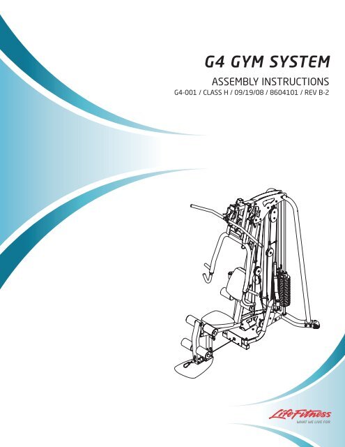
<strong>G4</strong> <strong>GYM</strong> <strong>SYSTEM</strong><br />
ASSEMBLY INSTRUCTIONS<br />
<strong>G4</strong>-001 / CLASS H / 09/19/08 / 8604101 / REV B-2
TABLE OF CONTENTS<br />
Safety Statement . . . . . . . . . . . . . . . . . . . . . . . . . . . . . . . . . . . . . . . . . . . . . . . . . . . . . . . . . . .1<br />
Important Notes . . . . . . . . . . . . . . . . . . . . . . . . . . . . . . . . . . . . . . . . . . . . . . . . . . . . . . . . . . . .3<br />
Tools Required for Assembly . . . . . . . . . . . . . . . . . . . . . . . . . . . . . . . . . . . . . . . . . . . . . . . . . . .3<br />
Gym Layout . . . . . . . . . . . . . . . . . . . . . . . . . . . . . . . . . . . . . . . . . . . . . . . . . . . . . . . . . . . . . . .4<br />
Parts List . . . . . . . . . . . . . . . . . . . . . . . . . . . . . . . . . . . . . . . . . . . . . . . . . . . . . . . . . . . . . . . . .5<br />
Assembly Instructions . . . . . . . . . . . . . . . . . . . . . . . . . . . . . . . . . . . . . . . . . . . . . . . . . . . . . . . .6<br />
General Maintenance . . . . . . . . . . . . . . . . . . . . . . . . . . . . . . . . . . . . . . . . . . . . . . . . . . . . . . .28<br />
Warranty Statement . . . . . . . . . . . . . . . . . . . . . . . . . . . . . . . . . . . . . . . . . . . . . . . . . . . . . . . .29<br />
Contact Information . . . . . . . . . . . . . . . . . . . . . . . . . . . . . . . . . . . . . . . . . . . . . . . . . . . . . . . . .30<br />
IMPORTANT SAFETY INFORMATION<br />
It is the sole responsibility of the purchaser of LIFE FITNESS products to read the owner's manual, warning labels and<br />
instruct all individuals, whether they are the end user or supervising personnel on proper usage of the equipment.<br />
UNDERSTANDING EACH AND EVERY WARNING TO THE FULLEST IS IMPORTANT. IF ANY OF THESE INSTRUC-<br />
TIONS OR WARNINGS ARE UNCLEAR, CONTACT LIFE FITNESS CUSTOMER SERVICE IMMEDIATELY AT 1-800-<br />
351-3737 WITHIN THE US AND CANADA. INTERNATIONAL OFFICE CONTACT INFORMATION IS AVAILABLE ON<br />
PAGE 30.<br />
Keep children away from strength equipment. Parent or others supervising children must provide close supervision of<br />
children if the equipment is used in the presence of children.<br />
This equipment is categorized as class H per EN 957-1. And as such this equipment is only intended for Home use. It is<br />
not intended for commercial, institutional and/or studio facilities use. Contact LIFE FITNESS with any questions regarding<br />
this classification.<br />
It is recommended that all users of LIFE FITNESS exercise equipment be informed of the following information prior to<br />
use.<br />
ACCESS CONTROL<br />
LIFE FITNESS recommends that all fitness equipment be used in a supervised area. It is recommended that the<br />
equipment be located in an access controlled area. Control is the responsibility of the facility owner.<br />
INSTALLATION<br />
SECURING EQUIPMENT - LIFE FITNESS recommends that all equipment be secured to a solid, level surface<br />
to stabilize and eliminate rocking or tipping over. This must be performed by a licensed contractor.<br />
PROPER USAGE<br />
1 Do not use any equipment in any way other than as designed or intended by the manufacturer. It is imperative<br />
that LIFE FITNESS equipment is used properly to avoid injury.<br />
2. Injuries may result if exercising improperly or excessively. It is recommended that all individuals consult a<br />
physician prior to commencing an exercise program. If at any time during exercise you feel faint, dizzy or<br />
experience pain, STOP EXERCIZING and consult your physician.<br />
3. Keep body parts (hands, feet, hair, etc.), clothing and jewelry away from moving parts to avoid injury.<br />
4. When adjusting any seat, knee hold down pad, range of motion limiter, foothold pad, pulley or any other type<br />
of adjuster, make certain that the adjusting pin is fully engaged in the hole to avoid injury.<br />
1
INSPECTION<br />
1. DO NOT use or permit use of any equipment that is damaged and or has worn or broken parts. For all LIFE<br />
FITNESS equipment use only replacement parts supplied by LIFE FITNESS.<br />
2. Cables and Belts pose an extreme liability if used when frayed. Always replace any cable at first sign of<br />
wear (consult LIFE FITNESS if uncertain).<br />
3. Routinely inspect all accessory clips that join attachments to the cables and replace at the first sign of wear.<br />
4. MAINTAIN LABELS AND NAMEPLATES - Do not remove labels for any reason. They contain important<br />
information. If unreadable or missing, contact LIFE FITNESS for a replacement.<br />
5. EQUIPMENT MAINTENANCE - Preventative maintenance is the key to smooth operating equipment as well<br />
as keeping your liability to a minimum. Equipment needs to be inspected at regular intervals.<br />
6. Ensure that any person(s) making adjustments or performing maintenance or repair of any kind is qualified<br />
to do so. LIFE FITNESS will provide service and maintenance training at our corporate facility upon request<br />
or in the field if proper arrangements are made.<br />
7. Before any use, examine all accessories approved for use with the LIFE FITNESS equipment for damage or<br />
wear.<br />
8. DO NOT ATTEMPT TO USE OR REPAIR ANY ACCESSORY APPROVED FOR USE WITH THE LIFE FIT-<br />
NESS EQUIPMENT WHICH APPEARS TO BE DAMAGED OR WORN.<br />
OPERATING WARNINGS<br />
1. It is the purchaser's sole responsibility to properly instruct its end users and supervising personnel as to the<br />
proper operating procedures of all LIFE FITNESS equipment.<br />
2. Keep children away from strength equipment. Parent or others supervising children must provide close<br />
supervision of children if the equipment is used in the presence of children.<br />
3. Do not allow users to wear loose fitting clothing or jewelry while using equipment. It is also recommended to<br />
have user's secure long hair back and up to avoid contact with moving parts.<br />
4. All bystanders must stay clear of all users, moving parts and attached accessories and components while<br />
machine is in operation.<br />
SELECTORIZED WEIGHT STACK <strong>SYSTEM</strong>S<br />
1. Use only weight selector pins supplied by LIFE FITNESS on weight stacks. Substitutes are forbidden.<br />
2. Fully insert weight selector pins. Partial insertion can cause weights to fall unexpectedly.<br />
3. Never pin the weight stack in an elevated position.<br />
4. Never remove selector pin if any weights are suspended.<br />
5. Never attempt to release jammed weights or parts.<br />
6. Never use dumbbells or other means to incrementally increase the weight resistance. Use only those means<br />
provided by LIFE FITNESS.<br />
Note: In our continuing effort to improve our products, specifications are subject to change.<br />
©2008 <strong>Life</strong> <strong>Fitness</strong>, a division of Brunswick Corporation. All rights reserved.<br />
www.lifefitness.com<br />
2
IMPORTANT NOTES<br />
Thank you for purchasing the <strong>Life</strong> <strong>Fitness</strong> <strong>G4</strong> Gym System. Please read these instructions thoroughly<br />
and keep them for future reference.<br />
This product must be assembled on a flat, level surface to assure its proper function. DO NOT<br />
securely tighten any frame connections until the entire frame has been assembled, unless<br />
otherwise stated.<br />
TOOLS REQUIRED FOR ASSEMBLY<br />
• Rubber mallet or hammer<br />
• 3/4” wrench<br />
• 9/16” wrench<br />
• Ratchet with 3/4” and 9/16” sockets<br />
• 5/32” Allen wrench<br />
• 6mm Allen wrench<br />
• 5/16” Allen wrench<br />
• 3/16” Allen wrench<br />
• Adjustable wrench<br />
• Tape measure<br />
BOLT LENGTH RULER<br />
Note: Bolt length is measured from the underside of the head of the bolt.<br />
BOLT LENGTH<br />
1/2 1/2 1/2 1/2 1/2 1/2<br />
0 1 2 3 4 5 6<br />
3
4<br />
1<br />
2<br />
3<br />
4<br />
5<br />
6<br />
7<br />
8<br />
9<br />
1 Square = 1’ X 1’<br />
1 2 3 4 5 6 7 8<br />
Minimum Required Usable Space<br />
Max User Weight = 300 pounds (136 kg)<br />
Length = 86 inches (219 cm)<br />
Width = 70 inches (178 cm)<br />
Height = 83 inches (211 cm)<br />
Weight = 484 pounds (220 kg)<br />
Dimensions Including GLP Leg Press (optional)<br />
Length = 107 inches (272 cm)<br />
Width = 101 inches (257 cm)<br />
Height = 83 inches (211 cm)<br />
9
PARTS LIST<br />
COMPONENTS PARTS LIST<br />
KEY<br />
DESCRIPTION QTY<br />
A<br />
FRAME<br />
1<br />
B<br />
BASE<br />
1<br />
C<br />
BASE PLATE<br />
2<br />
D<br />
BOOM PLATE LEFT 1<br />
E<br />
BOOM PLATE RIGHT 1<br />
F<br />
LEFT PEC FLYARM 1<br />
G<br />
RIGHT PEC FLYARM 1<br />
H<br />
PRESS ARM<br />
1<br />
I<br />
PEC FLY HANDLE 2<br />
J<br />
SEATADJUST<br />
1<br />
K<br />
LEG PEDESTAL 1<br />
L<br />
FOOT PLATE<br />
1<br />
M<br />
LEFT REAR UPRIGHT 1<br />
N<br />
RIGHT REAR UPRIGHT 1<br />
O<br />
PEC PLATE<br />
1<br />
P<br />
“L” CABLE RETAINER 2<br />
Q<br />
3-1/2” PULLEY GUARD 2<br />
R<br />
SHORT “L” CABLE BRACE 2<br />
S<br />
LONG “L” CABLE BRACE 1<br />
T<br />
3/4 X 17-7/8” TUBE 1<br />
U<br />
3/4 X 18-3/8” TUBE 1<br />
V<br />
3/4 X 21” TUBE 1<br />
W<br />
BACK INCLINE ADJUST 1<br />
X<br />
PRESS ARM SUPPORT FRAME 1<br />
Y<br />
PRESS ARM ADJUSTMENT 1<br />
Z<br />
FLOATING PULLEY BRKT 1<br />
AA<br />
DBL FLOATING PULLEY BRKT ASSY 1<br />
AB<br />
DBL FLOATING PULLEY 2<br />
AC<br />
GUIDE ROD 2<br />
AD<br />
WEIGHT STACK SPACER 2<br />
AE<br />
WEIGHT STACK CUSHION 2<br />
AF<br />
HEAD PLATE ASSY 1<br />
AG<br />
LAT BAR ASSY 1<br />
AH<br />
LOW ROW BAR 1<br />
AI<br />
SEAT PAD<br />
1<br />
AJ<br />
ROLLER PAD 6<br />
AK<br />
AB STRAP<br />
1<br />
AL<br />
ANKLE STRAP 1<br />
AM<br />
LAT CABLE 199-3/6” 1<br />
AN<br />
LOW CABLE 168” 1<br />
AO<br />
GUIDE CABLE 96” 1<br />
AP<br />
PEC FLY CABLE 90-1/2” 1<br />
AQ<br />
WEIGHT PLATE LABEL 1<br />
AR BACK PAD 1<br />
AS WEIGHT PLATES 15<br />
Note: Some of the parts listed may be pre-installed.<br />
KEY<br />
1<br />
2<br />
3<br />
4<br />
5<br />
6<br />
7<br />
8<br />
9<br />
10<br />
11<br />
12<br />
13<br />
14<br />
15<br />
16<br />
17<br />
18<br />
19<br />
20<br />
21<br />
22<br />
23<br />
24<br />
25<br />
26<br />
27<br />
28<br />
29<br />
30<br />
31<br />
32<br />
33<br />
34<br />
35<br />
36<br />
37<br />
38<br />
HARDWARE PARTS LIST<br />
PART<br />
DESCRIPTION<br />
1/2 X 5-3/4” BOLT<br />
1/2 X 104mm BOLT<br />
3/8 X 8” BOLT<br />
3/8 X 5-3/4” BOLT<br />
3/8 X 4” BOLT<br />
3/8 X 3-3/4” BOLT<br />
3/8 X 3-1/4” BOLT<br />
3/8X3”BLK BOLT<br />
3/8 X 2-3/4” BOLT<br />
3/8X3”SILVER BOLT<br />
3/8 X 1-3/4” BOLT<br />
3/8 X 1-1/4” BOLT<br />
3/8” SHIMWASHER<br />
3/8 X 3/4” BOLT<br />
1/2 X 3/4” BTN HEAD<br />
3/8 X 1” FLAT HEAD<br />
1/2” FLAT WASHER<br />
3/8” FLAT WASHER<br />
3/8 ”SILVER LOCK NUT<br />
1/2” LOCK NUT<br />
CHAIN<br />
SNAP LINK<br />
CABLE WIRE GUIDE<br />
1” SPACER<br />
1-1/4” SPACER<br />
1-1/16” STEP SPACER<br />
11/16” STEP SPACER<br />
1/2” STEP SPACER<br />
SHAFT COLLAR<br />
ROLLER PAD CAP<br />
3/8” STAR KNOB<br />
RH CAP<br />
3/4” PLASTIC WASHER<br />
PLASTIC SLEEVE<br />
3-1/2” PULLEY<br />
4-1/2” PULLEY<br />
V PULLEY<br />
5/16 x 1” BTN HEAD<br />
QTY<br />
1<br />
1<br />
2<br />
1<br />
1<br />
24<br />
2<br />
2<br />
2<br />
2<br />
5<br />
2<br />
2<br />
2<br />
4<br />
2<br />
2<br />
15<br />
39<br />
2<br />
1<br />
4<br />
1<br />
11<br />
2<br />
6<br />
2<br />
2<br />
2<br />
6<br />
1<br />
2<br />
12<br />
2<br />
20<br />
2<br />
1<br />
6<br />
39 PULLEY GUARD 2<br />
40<br />
3/8” BLACK LOCK NUT 2<br />
41<br />
SILICON<br />
1<br />
42<br />
<strong>G4</strong> EXERCISE CARD 1<br />
43<br />
TOUCH-UP PAINT(PLAT) 1<br />
44<br />
TOUCH-UP PAINT(SHDW GRY) 1<br />
5
STEP 1:<br />
• LOOSELY assemble two BASE PLATES (C) to the FRAME (A) and BASE (B) using three 3/8 X<br />
3-3/4” BOLTS (6) and three 3/8” SILVER LOCK NUTS (19). See FIGURE 1.<br />
• LOOSELY assemble the FOOTPLATE (L) to the lower holes in FRAME (A) using one 3/8 X 3”<br />
BOLT (8) and one 3/8” BLACK LOCK NUT (40) as shown in FIGURE 1.<br />
6<br />
FIGURE 1<br />
3/8 X 3-3/4<br />
3/8 X 3” 8<br />
L<br />
6<br />
40<br />
A<br />
B<br />
C<br />
19
CHECK THAT THE WEIGHT PLATES (AS) AND HEAD PLATE (AF)<br />
ARE ASSEMBLED AS SHOWN IN FIGURES 2 & 3.<br />
AF<br />
AS<br />
FIGURE 2<br />
FIGURE 3<br />
7
8<br />
FIGURE 4<br />
S<br />
BOTTOM<br />
T<br />
STEP 4:<br />
• Place the GUIDE RODS (AC) through the BOTTOM SHROUD BRACKET and into the BASE<br />
FRAME (B) as shown in FIGURE 4.<br />
• Note: Lubricate the GUIDE RODS (AC) with the included silicon package.<br />
• Slide two WEIGHT STACK SPACERS (AD) and two WEIGHT STACK CUSHIONS (AE) down<br />
over the GUIDE RODS (AC).<br />
• Using EXTREME CARE slide all fifteen WEIGHT PLATES (AS) down over the GUIDE RODS<br />
(AC) on to the WEIGHT STACK CUSHIONS (AE). Make sure that the WEIGHT PLATES (AS)<br />
are all facing as shown.<br />
• Slide the HEAD PLATE (AF) down over the GUIDE RODS (AC) onto the weight stack.<br />
• Slide two SHAFT COLLARS (29) over the GUIDE RODS (AC) as shown in FIGURE 4.<br />
• Apply WEIGHT STACK LABELS (AQ) to the WEIGHT PLATES (AS) and the HEAD PLATE (AF)<br />
as shown in FIGURE 4. Begin with number one at the HEAD PLATE (AF) with larger numbers in<br />
consecutive order towards the bottom of the weight stack.
STEP 5:<br />
FIGURE 5<br />
E 14<br />
• Carefully slide the RIGHT (N) and LEFT (M) REAR UPRIGHTS over the GUIDE RODS (AC) as<br />
shown in FIGURE 5 and SECURELY assemble the RIGHT (N) and LEFT (M) REAR UPRIGHTS<br />
to the BASE (B) using four 3/8 X 3-3/4” BOLTS (6), four 3/8” WASHERS (18) and four 3/8” SIL-<br />
VER LOCK NUTS (19) as shown in FIGURE 5.<br />
• SECURELY assemble the RIGHT (E) and LEFT (D) BOOM PLATES to the RIGHT (N) and LEFT<br />
(M) REAR UPRIGHTS using two 3/8 X 3/4” BOLTS W/LOCKTITE (14) as shown in FIGURE 5.<br />
1/2 1/2 1/2 1/2 1/2 1/2<br />
0 1 2 3 4 5 6<br />
B<br />
AC<br />
D<br />
M<br />
9
STEP 6:<br />
• SECURELY assemble the LEFT (D) and RIGHT (E) BOOM PLATES to the FRAME (A) using two<br />
3/8 X 3-3/4” BOLTS (6) and two 3/8” SILVER LOCK NUTS (19). See FIGURE 6.<br />
• Slide up both SHAFT COLLARS (29) to the top until flush with the bottom of the guide rod bushings<br />
in both the LEFT (M) and RIGHT (N) REAR UPRIGHTS and SECURELY TIGHTEN as<br />
shown in FIGURE 6.<br />
10<br />
A<br />
FIGURE 6<br />
N E<br />
AC<br />
D<br />
M
G<br />
STEP 7:<br />
B<br />
• Securely tighten all frame connections except the FOOTPLATE/FRAME connection as noted in<br />
FIGURE 7.<br />
• Slide the LEFT (F) and RIGHT (G) PEC FLY ARMS over the BASE (B) as shown in FIGURE 7.<br />
• SECURELY assemble the PEC FLY HANDLES (I) to the LEFT (F) and RIGHT (G) PEC FLY<br />
ARMS using two 1/2 X 3/4” BUTTON HEAD BOLTS (15), and two 1/2” WASHERS (17) as shown<br />
in FIGURE 7.<br />
1/2 1/2 1/2 1/2 1/2 1/2<br />
0 1 2 3 4 5 6<br />
F<br />
15<br />
FIGURE 7<br />
11
STEP 9:<br />
• Assemble the LEG PEDESTAL (K) to the FRAME (A) using two RH CAPS (32), one 1/2 X 104mm BOLT (2), two<br />
3/8” SHIM WASHERS (13), and one 1/2” LOCK NUT (20). (Note: Tighten this connection enough to remove<br />
excess play yet allow the LEG PEDESTAL to rotate freely.)<br />
• Assemble two ROLLER PADS (AJ) to the LEG PEDESTAL (K) using one 3/4 X 17-7/8” TUBE (T), and four PLASTIC<br />
WASHERS (33).<br />
• Assemble two ROLLER PAD CAPS (30) using two 5/16” X 1” ALLEN SCREWS (38) as shown in FIGURE 9.<br />
12<br />
FIGURE 8<br />
STEP 8:<br />
• SECURELY assemble the PEC PLATE (O) to the BASE (B) using two 3/8 X 2-3/4” BOLTS (9), one 3/8 X 4” BOLT<br />
(5), two 3/8” WASHERS (18) and three 3/8” SILVER LOCK NUTS (19) as shown in FIGURE 8.<br />
• SECURELY assemble the LEFT (F) and RIGHT (G) PEC FLY ARMS to the BASE (B) using two 1/2 X 3/4” BUTTON<br />
HEAD BOLTS (15) as shown in FIGURE 8. (Note: Tighten this connection enough to remove excess play yet<br />
allow the PEC FLY ARMS freely.)<br />
FIGURE 9<br />
18
STEP 10:<br />
FIGURE 10<br />
• SECURELY assemble the SEAT PAD (AI) to the SEAT ADJUST (J) using two 3/8 X 3” SILVER BOLTS (10) and two<br />
3/8” WASHERS (18).<br />
• Assemble two ROLLER PADS (AJ) to the SEAT ADJUST (J) using one 3/4 X 18-3/8” TUBE (U), four PLASTIC<br />
WASHERS (33), two ROLLER PAD CAPS (30), and two 5/16 X 1” ALLEN SCREWS (38) as shown in FIGURE 10.<br />
• CAREFULLY insert the SEAT ADJUST ASSEMBLY into the FRAME (A) as shown. The SEAT height can be adjusted<br />
using the PLUNGER PIN.<br />
AJ<br />
38<br />
FIGURE 11<br />
AR<br />
33<br />
1<br />
STEP 11:<br />
• SECURELY assemble the BACK PAD (AR) to the BACK INCLINE ADJUST (W) using two 3/8 X 1-1/4” BOLTS (12).<br />
• SECURELY assemble the BACK INCLINE ADJUST (W) to the FRAME (A) using one 1/2 X 5-3/4” BOLT (1) and one<br />
1/2” LOCK NUT (20). The BACK PAD angle can be adjusted using the PLUNGER. (Note: Tighten this connection<br />
enough to remove excess play yet allow the BACK INCLINE ADJUST to rotate freely.)<br />
• Assemble two ROLLER PADS (AJ) to the BACK INCLINE ADJUST (W) using one 3/4 X 21” TUBE (V), four PLAS-<br />
TIC WASHERS (33), two ROLLER PAD CAPS (30), and two 5/16 X 1” ALLEN SCREWS (38) as shown in FIGURE<br />
11.<br />
W<br />
12<br />
18<br />
A<br />
13
STEP 12:<br />
• Disassemble one of the BEARING BLOCKS from the PRESS ARM SUPPORT FRAME (X) and<br />
remove the PRESS ARM SUPPORT PIVOT as shown in FIGURE 12.<br />
• Insert the PRESS ARM SUPPORT PIVOT thru the PRESS ARM SUPPORT FRAME (X) and the<br />
FRAME (A). Assemble the BEARING BLOCKS to the PRESS ARM SUPPORT FRAME (X) as<br />
shown in FIGURE 12.<br />
• SECURELY tighten the two 5/16 X 1/4” SET SCREWS (PRE-INSTALLED) on the FRAME (A) as<br />
shown in FIGURE 12.<br />
• SECURELY assemble the PRESS ARM ADJUSTMENT PLATE (Y) to the PRESS ARM SUP-<br />
PORT FRAME (X) using two 3/8 X 1” FLAT HEAD ALLEN BOLTS (16) as shown in FIGURE 12.<br />
14<br />
FIGURE 12<br />
1/2 1/2 1/2 1/2 1/2 1/2<br />
0 1 2 3 4 5 6
STEP 13:<br />
FIGURE 13<br />
FLAT<br />
• Disassemble the PRESS ARM PIVOT SHAFT from the PRESS ARM (H) by removing the two 3/8 X 3/4” ALLEN<br />
SCREWS and two 3/8” FLAT WASHERS as shown in FIGURE 13.<br />
• Insert the PRESS ARM PIVOT SHAFT thru the PRESS ARM (H) and the PRESS ARM SUPPORT FRAME (X) and<br />
then reassemble the 3/8 X 3/4” ALLEN SCREWS and 3/8” FLAT WASHERS to the PRESS ARM PIVOT SHAFT as<br />
shown in FIGURE 13. (Note: Tighten this connection enough to remove excess play yet allow the PRESS ARM<br />
to rotate freely.)<br />
• Pull back on the SPRING PIN and rotate the PRESS ARM (H) until the SPRING PIN connects with the PRESS ARM ADJUST-<br />
MENT (Y).<br />
15
STEP 14:<br />
• Route the LAT CABLE (AM) through the FRAME (A) and assemble one 3-1/2” PULLEY (35) to the<br />
FRAME (A) using one 3/8” X 3-3/4” BOLT (6), two 3/8” X 1-1/16” FLANGE SPACERS (26), and<br />
one 3/8” SILVER LOCK NUT (19). See FIGURE 14.<br />
NOTE: Make sure the cable runs in the grooves of the pulleys.<br />
16<br />
FIGURE 14<br />
1/2 1/2 1/2 1/2 1/2 1/2<br />
0 1 2 3 4 5 6
STEP 15:<br />
FIGURE 15<br />
• Route the LAT CABLE (AM) through the PRESS ARM SUPPORT FRAME (X) and assemble one<br />
3-1/2” PULLEY (35) to the FRAME PRESS ARM SUPPORT FRAME (X) using one 3/8 X 8” BOLT<br />
(3), two 3/8” WASHERS (18), two PULLEY GUARD SPACERS (39) and one 3/8” SILVER LOCK<br />
NUT (19). See FIGURE 15.<br />
• Route the LAT CABLE (AM) around one 3-1/2” PULLEY (35) and assemble the PULLEY to the<br />
LEFT (D) and RIGHT (E) BOOM PLATES using one 3/8 X 3-3/4” BOLT (6), two 3/8 X 1” SPAC-<br />
ERS (24) and one 3/8” SILVER LOCK NUT (19). See FIGURE 15.<br />
NOTE: Make sure the cable runs in the grooves of the pulleys.<br />
39<br />
17
STEP 16:<br />
• Route the LAT CABLE (AM) through the PRESS ARM SUPPORT FRAME (X) and assemble one<br />
3-1/2” PULLEY (35) to the FRAME PRESS ARM SUPPORT FRAME (X) using one 3/8 X 8” BOLT<br />
(3), two 3/8” WASHERS (18), two 3/8 X 1-1/4” SPACERS (25) and one 3/8” SILVER LOCK NUT<br />
(19). See FIGURE 16.<br />
• Route the LAT CABLE (AM) through the FRAME (A) and assemble one 3-1/2” PULLEY (35) to<br />
the FRAME (A) using one 3/8 X 3-3/4” BOLT (6), two 3/8 X 1-1/16” FLANGE SPACERS (26) and<br />
one 3/8” SILVER LOCK NUT (19). See FIGURE 16.<br />
• Route the LAT CABLE (AM) around one 3-1/2” PULLEY (35) and assemble the PULLEY to the<br />
DOUBLE FLOATING PULLEY BRACKET ASSEMBLY (AA) using one 3/8 X 1-3/4” BOLT (11) and<br />
one 3/8” SILVER LOCK NUT (19). See FIGURE 16.<br />
NOTE: Make sure the cable runs in the grooves of the pulleys.<br />
18<br />
FIGURE 16<br />
1/2 1/2 1/2 1/2 1/2 1/2<br />
0 1 2 3 4 5 6
STEP 17:<br />
AM<br />
• Route the LAT CABLE (AM) around one 4-1/2” PULLEY (36) and assemble the PULLEY to the<br />
LEFT (D) and RIGHT (E) BOOM PLATES using one 3/8 X 3-3/4” BOLT (6), one LONG “L” CABLE<br />
BRACE (S), one 1” SPACER (24) and one 3/8” SILVER LOCK NUT (19). See FIGURE 17.<br />
• SECURELY assemble two PLASTIC SLEEVES (34) to the LEFT (D) and RIGHT (E) BOOM<br />
PLATES using two 3/8 X 3-3/4” BOLTS (6) and two 3/8” SILVER LOCK NUTS (19) as shown in<br />
FIGURE 17.<br />
• Route the LAT CABLE (AM) around one 3-1/2” PULLEY (35) and assemble two DOUBLE FLOAT-<br />
ING PULLEY PLATES (AB) to the 3-1/2” PULLEY (35) using one 3/8 X 1-3/4” BOLT (11) and one<br />
3/8” SILVER LOCK NUT (19). See FIGURE 17. (Note: Make sure the cable runs in the<br />
grooves of the pulleys.)<br />
• Route the LAT CABLE (AM) over two 3-1/2” PULLEYS (35) and assemble the PULLEYS to the<br />
LEFT (D) and RIGHT (E) BOOM PLATES using two 3/8 X 3-3/4” BOLTS (6), two SHORT “L”<br />
CABLE BRACES (R), two 1” SPACERS (24) and two 3/8” SILVER LOCK NUTS (19). See FIG-<br />
URE 17.<br />
• Screw the threaded end of the LAT CABLE (AM) into the end of the HEAD PLATE ASSEMBLY<br />
(AF). See FIGURE 17.<br />
36<br />
19<br />
FIGURE 17<br />
19
STEP 18:<br />
• Securely assemble the PEC FLY CABLE (AP) to the LEFT PEC ARM (F) as shown in FIGURE 18.<br />
• Assemble one 3-1/2” PULLEY (35) to the PEC PLATE (O) using one 3/8 X 3-1/4” BOLT (7), one “L” CABLE RETAIN-<br />
ER (P) and one 3/8” SILVER LOCK NUT (19). See FIGURE 18. (Note: Loop the PEC FLY CABLE (AP) around the<br />
PULLEY prior to assembling the PULLEY to the PEC PLATE.)<br />
• Assemble two 3-1/2” PULLEYS (35) to the BASE PLATES (C) using one 3/8 X 5-3/4” BOLT (4), two PULLEY<br />
GUARDS (Q) and one 3/8” SILVER LOCK NUT (19). See FIGURE 18. (Note: Loop the PEC FLY CABLE (AP)<br />
around the PULLEY prior to assembling the PULLEY to the PEC PLATE.)<br />
• Route the PEC FLY CABLE (AP) around one 4-1/2” PULLEY (36) and assemble the 4-1/2” PULLEY (36) to the DOU-<br />
BLE FLOATING PULLEY BRACKET ASSEMBLY (AA) using one 3/8” X 1-3/4” BOLT (11) and one 3/8” SILVER LOCK<br />
NUT (19). See FIGURE 18.<br />
• Assemble one 3-1/2” PULLEY (35) to the PEC PLATE (O) using one 3/8 X 3-1/4” BOLT (7), one “L” CABLE RETAIN-<br />
ER (P) and one 3/8” SILVER LOCK NUT (19). See FIGURE 18. (Note: Loop the PEC FLY CABLE (AP) around the<br />
PULLEY prior to assembling the PULLEY to the PEC PLATE.)<br />
• Securely assemble the PEC FLY CABLE (AP) to the RIGHT PEC ARM (G) as shown in FIGURE 18.<br />
20<br />
19<br />
FIGURE 18<br />
1/2 1/2 1/2 1/2 1/2 1/2<br />
0 1 2 3 4 5 6<br />
19
STEP 19:<br />
FIGURE 19<br />
• Screw the threaded end of the GUIDE CABLE (AO) into the end of the FLOATING PULLEY<br />
BRACKET (Z). Secure the CABLE GUIDE (23) in place with the JAM NUT on the GUIDE CABLE.<br />
See FIGURE 19.<br />
• Route the GUIDE CABLE (AO) around one 3-1/2” PULLEY (35) and assemble the PULLEY to the<br />
FLOATING PULLEY PLATES (AB) using one 3/8 X 1-3/4” BOLT (11) and one 3/8” SILVER LOCK<br />
NUT (19). See FIGURE 19. (Note: Make sure the cable runs in the grooves of the pulleys.)<br />
• Route the hook end of the GUIDE CABLE (AO) thru the CABLE GUIDE (23) then the GUIDE<br />
CABLE (AO) to the BASE using one 3/8 X 3-3/4” BOLT (6), one 3/8” WASHER (18) and one 3/8”<br />
SILVER LOCK NUT (19) as shown in FIGURE 19.<br />
21
STEP 20:<br />
• Route the large ball end of the LOW CABLE (AN) around one V- PULLEY (37) and assemble the<br />
PULLEY to the FRAME (A) using two 3/8 X 3-3/4” BOLTS (6), two 1/2” FLANGE SPACERS (28),<br />
two 3/8” WASHERS (18) and two 3/8” SILVER LOCK NUTS (19) as shown in FIGURE 20.<br />
• Route the small ball end of the LOW CABLE (AN) through the BASE PLATES (C) and assemble<br />
two 3-1/2” PULLEYS (35) to the BASE PLATES (C) using two 3/8 X 3-3/4” BOLTS (6), four 1”<br />
SPACERS (24) and two 3/8” SILVER LOCK NUTS (19). See FIGURE 20.<br />
22<br />
FIGURE 20<br />
3/8 X 3-3/4” 6<br />
18<br />
28<br />
A<br />
AN<br />
37<br />
19<br />
C<br />
6 3/8 X 3-3/4”<br />
24<br />
35<br />
19
STEP 21:<br />
FIGURE 21<br />
AN<br />
3/8 X 1-3/4” 11<br />
6 3/8 X 3-3/4”<br />
• Route the LOW CABLE (AN) around one 3-1/2” PULLEY (35) and assemble the PULLEY to the<br />
PULLEY BRACKET (Z) using one 3/8 X 1-3/4” BOLT (11) and one 3/8” SILVER LOCK NUT (19)<br />
as shown in FIGURE 21.<br />
• Route the LOW CABLE (AN) through the BASE PLATES (C) and assemble one 3-1/2” PULLEY<br />
(35) to the BASE PLATES (C) using one 3/8 X 3-3/4” BOLT (6), two 1” SPACERS (24) and one<br />
3/8” SILVER LOCK NUT (19). See FIGURE 21.<br />
7<br />
35<br />
C<br />
19<br />
35<br />
24<br />
19<br />
23
STEP 22:<br />
• Assemble one 3-1/2” PULLEY (35) to the FOOT PLATE (L) using one 3/8 X 3” BLACK BOLT (8),<br />
two STEP SPACERS 11/16” (27) and one 3/8” BLACK LOCK NUT (40). See FIGURE 22.<br />
• Route the small ball end of the LOW CABLE (AN) around one 3-1/2” PULLEY (35) and assemble<br />
the PULLEY to the LEG PEDESTAL (K) using one 3/8 X 3-3/4” BOLT (6), two 1-1/16” STEP<br />
SPACERS (26) and one 3/8” SILVER LOCK NUT (19) as shown in FIGURE 22. (NOTE: The<br />
LOW CABLE (AN) should be routed over the retaining bolt as shown in FIGURE 22.)<br />
24<br />
FIGURE 22<br />
1/2 1/2 1/2 1/2 1/2 1/2<br />
0 1 2 3 4 5 6<br />
40
STEP 23:<br />
FIGURE 23<br />
• If upon completion of assembly, the HEAD PLATE (AF) does not sit on top of the first WEIGHT<br />
PLATE, push the HEAD PLATE (AF) down, insert the WEIGHT SELECTOR PIN and perform several<br />
repetitions at the press station. This will relax the cable system and prevent the HEAD PLATE<br />
(AF) from lifting up. See FIGURE 23.<br />
• If after completing the previous step, the HEAD PLATE (AF) still does not sit on top of the first<br />
WEIGHT PLATE or if there is excess slack in the cable system, adjust the threaded end of the<br />
LAT CABLE (AM) and ADJUSTABLE GLIDE accordingly and retighten the jam nuts. See FIGURE<br />
23.<br />
• For maximum performance, the HEAD PLATE (AF) should just barely sit on the top WEIGHT<br />
PLATE.<br />
• Attach the LAT BAR (AG) to the ball end of LAT CABLE (AM) using one SNAP LINK (22) as<br />
shown in FIGURE 23.<br />
• Attach the ANKLE STRAP (AL) to the 12 LINK CHAIN (21) using one SNAP LINK (22) as shown<br />
in FIGURE 23.<br />
• Attach the AB STRAP (AK) to the ball end of LOW CABLE (AN) using one SNAP LINK (22) as<br />
shown in FIGURE 23.<br />
25
STEP 24:<br />
• SECURELY assemble the TOP SHROUD BRACKET (3) to the RIGHT and LEFT BOOM PLATES<br />
using two 3/8 X 2-1/2” BOLTS (7) and two 3/8” BLACK LOCK NUTS (8) as shown in FIGURE 24.<br />
The BOTTOM SHROUD BRACKET (4) was previously inserted under the weight stack.<br />
26<br />
KEY<br />
1<br />
2<br />
3<br />
4<br />
DESCRIPTION<br />
LEFT SHROUD<br />
RIGHT SHROUD<br />
TOP SHROUD BRACKET<br />
BOTTOM SHROUD BRACKET<br />
PARTS LIST<br />
QTY<br />
1<br />
1<br />
1<br />
1<br />
DESCRIPTION<br />
3/8 X 1” BUTTON HEAD BOLT<br />
3/8” BLACK SAE WASHER<br />
3/8 X 2-1/2” BOLT<br />
3/8” LOCK NUT<br />
FIGURE 24 7 3/8 X 2-1/2”<br />
Note: Figure 24 Depicts the<br />
G3 Gym System. Assembly<br />
is the same as the <strong>G4</strong> Gym<br />
System.<br />
KEY<br />
5<br />
6<br />
7<br />
8<br />
RIGHT BOOM PLATE<br />
8<br />
LEFT BOOM PLATE<br />
3<br />
4<br />
QTY<br />
8<br />
8<br />
2<br />
2
STEP 25:<br />
KEY<br />
1<br />
2<br />
3<br />
4<br />
DESCRIPTION<br />
LEFT SHROUD<br />
RIGHT SHROUD<br />
TOP SHROUD BRACKET<br />
BOTTOM SHROUD BRACKET<br />
QTY<br />
1<br />
1<br />
1<br />
1<br />
PARTS LIST<br />
DESCRIPTION<br />
3/8 X 1” BUTTON HEAD BOLT<br />
3/8” BLACK SAE WASHER<br />
3/8 X 2-1/2” BOLT<br />
3/8” LOCK NUT<br />
FIGURE 25 7 3/8 X 2-1/2”<br />
Note: Figure 25 depicts<br />
the G3 Gym System.<br />
Assembly is the same as<br />
the <strong>G4</strong> Gym System.<br />
• SECURELY assemble the LEFT SHROUD (1) and RIGHT SHROUD (2) to the TOP (3) and BOT-<br />
TOM (4) SHROUD BRACKETS using eight 3/8 X 1” BUTTON HEAD BOLTS (5) and eight 3/8”<br />
BLACK SAE WASHERS (6) as shown in FIGURE 21.<br />
• One M4 X 20mm SHOULDER BOLT, M4 WASHER, and M4 NUT are pre-assembled to the<br />
shroud. Use use the M4 X 20MM SHOULDER BOLT to hang the <strong>G4</strong> Exercise Cards.<br />
KEY<br />
5<br />
6<br />
7<br />
8<br />
RIGHT BOOM PLATE<br />
8<br />
4<br />
3<br />
QTY<br />
8<br />
8<br />
2<br />
2<br />
LEFT BOOM PLATE<br />
This completes the assembly of the <strong>G4</strong> Gym System.<br />
27
MAINTENANCE<br />
28<br />
� We recommend cleaning your product (pads and frame) on a regular basis, using warm<br />
soapy water. Touch-up paint can be purchased from your <strong>Life</strong> <strong>Fitness</strong> customer service representative<br />
at 1-800-351-3737.<br />
� Inspect equipment daily. Tighten all loose connections and replace worn parts immediately.<br />
Failure to do so may result in serious injury.<br />
� Lubricate the guide rods with a teflon based (or equivalent) lubricant on a regular basis.<br />
� PLEASE RECORD THE INFORMATION REQUESTED BELOW. IN THE EVENT THAT<br />
YOUR EQUIPMENT REQUIRES SERVICE YOU WILL BE ASKED FOR THIS INFORMA-<br />
TION.<br />
Remember to fill out your registration card on-line at www.lifefitness.com/registration.<br />
MODEL #______________________________________________________<br />
SERIAL #______________________________________________________<br />
DATE OF PURCHASE: ___________________________________________<br />
DEALER’S NAME: ______________________________________________<br />
DEALER’S PHONE # ____________________________________________<br />
THANK YOU FOR PURCHASING THE LIFE FITNESS <strong>G4</strong> <strong>GYM</strong> <strong>SYSTEM</strong>!<br />
SERIAL NUMBER LOCATED<br />
ON BACK OF BASE AND ON<br />
FRONT UPRIGHT
WARRANTY<br />
<strong>Life</strong> <strong>Fitness</strong> extends the following LIMITED WARRANTY to the original owner of the <strong>Life</strong> <strong>Fitness</strong> products. The Warranty<br />
terms apply to IN HOME USE ONLY.<br />
1. LIMITED WARRANTY ON FRAME AND WELDS. If the frame of the <strong>Life</strong> <strong>Fitness</strong> product or a weld should crack or<br />
break, it will be repaired or replaced by <strong>Life</strong> <strong>Fitness</strong>. Terms: <strong>Life</strong>time – for so long as the Customer owns the <strong>Life</strong><br />
<strong>Fitness</strong> product.<br />
2. LIMITED WARRANTY ON PARTS. If the following parts are defective in material or workmanship, <strong>Life</strong> <strong>Fitness</strong> will<br />
supply replacement parts: all bolts, nuts, washers, bearings, bushings, pulleys, thumbscrews, collars, cable retaining<br />
clips, adjustable pre-stretch slides, roller pad shafts, allen head bolts, weight selector pin, weight stack shaft, set<br />
screws, protector caps, adjustment chain, cotter pin, plunger, spring and knob. Terms: <strong>Life</strong>time – for so long as the<br />
Customer owns the <strong>Life</strong> <strong>Fitness</strong> product.<br />
3. LIMITED WARRANTY ON CABLES AND UPHOLSTERY. If the coated cables or upholstery are defective in material<br />
or workmanship, <strong>Life</strong> <strong>Fitness</strong> will repair or replace them, at its option. Terms: Three (3) years.<br />
4. CONDITIONS AND EXCEPTIONS. Any product misuse, abuse or alteration, any attempt to repair by a person other<br />
than an authorized <strong>Life</strong> <strong>Fitness</strong> Service Center, any improper assembly, accident, or any other condition resulting<br />
from occurrences beyond the control of <strong>Life</strong> <strong>Fitness</strong> will void this Limited Warranty.<br />
5. REPLACEMENT AND REPAIR EXPENSES. <strong>Life</strong> <strong>Fitness</strong> will provide only replacement parts or repair under this warranty.<br />
The Owner is responsible for all other costs. Such costs may include, but are not limited to: a. labor charges<br />
for service, removal, repair or reinstallation of the <strong>Life</strong> <strong>Fitness</strong> product or any component part; b. shipping, delivery,<br />
handling and administrative charges for returning parts to <strong>Life</strong> <strong>Fitness</strong>; and c. all necessary or incidental costs related<br />
to installation of the replacement parts.<br />
6. SHIPPING. If shipping by the Owners is deemed necessary (in sole discretion of <strong>Life</strong> <strong>Fitness</strong>), parts should be<br />
shipped in their original carton or equivalent packaging, fully insured with shipping charges prepaid. <strong>Life</strong> <strong>Fitness</strong> will<br />
not assume any responsibility for any loss or damage incurred in shipping.<br />
7. CLAIM PROCEDURES. If service on your <strong>Life</strong> <strong>Fitness</strong> product is required during the warranty period, please contact<br />
our Customer Service Department at 1-800-351-3737 for instructions regarding returning or replacing parts. Please<br />
have available the following information: (i) the dealer’s name; (ii) the date of purchase; (iii) the serial # (s) of your<br />
product (the serial number location is called out on the final assembly drawing included with your assembly instruction);<br />
(iv) a description of the nature of the problem.<br />
8. OWNER’S RIGHT. This Limited Warranty gives you specific legal rights. You may also have other rights, which vary<br />
depending on local law.<br />
9. LIMITATION OF IMPLIED WARRANTIES. All implied warranties, except to the extent prohibited by applicable law,<br />
shall have no greater duration than the warranty period set forth above. There are no warranties which extend<br />
beyond the description in this Limited Warranty.<br />
Because local laws do not allow limitations on how long an implied warranty lasts, the above limitations may not<br />
apply to you.<br />
10. DISCLAIMER. No other express warranty has been made or will be made on behalf of <strong>Life</strong> <strong>Fitness</strong> with respect to<br />
any <strong>Life</strong> <strong>Fitness</strong> product or the operation, repair or replacement of any <strong>Life</strong> <strong>Fitness</strong> product. <strong>Life</strong> <strong>Fitness</strong> shall not be<br />
responsible for injury, loss of use of the <strong>Life</strong> <strong>Fitness</strong> product, inconvenience, loss or damage to personal property,<br />
whether direct or indirect, and incidental or consequential damages. The above limitation or exclusion may not apply<br />
to you.<br />
29
30<br />
AMERICAS<br />
North America<br />
<strong>Life</strong> <strong>Fitness</strong> Inc.<br />
5100 N River Road<br />
Schiller Park, IL 60176 U.S.A<br />
Telephone: +1(847) 288 3300<br />
Fax: +1(847) 288 3703<br />
Service Email: internationalservicesupport@lifefitness.com<br />
Sales/Marketing Email: commercialsales@lifefitness.com<br />
Operating Hours: 7:00 am-6:00 pm (CST)<br />
Brazil<br />
<strong>Life</strong> <strong>Fitness</strong> Do Brazil<br />
Av. Dr. Dib Sauaia Neto 1478<br />
Alphaville, Barueri, SP<br />
06465-140<br />
BRAZIL<br />
Telephone: (800) 773 8282<br />
Fax: (+55) 11.4133.2893<br />
Service Email: suporte@lifefitness.com.br<br />
Sales/Marketing Email: lifefitness@lifefitness.com.br<br />
Operating Hours: 8:30 am-17:30 pm (BRT)<br />
Latin America & Caribbean*<br />
<strong>Life</strong> <strong>Fitness</strong> Inc.<br />
5100 N River Road<br />
Schiller Park, IL 60176 U.S.A<br />
Telephone: +1(847) 288 3300<br />
Fax: +1(847) 288 3703<br />
Service Email: internationalservicesupport@lifefitness.com<br />
Sales/Marketing Email:commercialsales@lifefitness.com<br />
Operating Hours: 8:00am-5:00pm (CST)<br />
EUROPE, MIDDLE EAST, & AFRICA<br />
(EMEA)<br />
Netherlands & Luxemburg<br />
<strong>Life</strong> <strong>Fitness</strong> Atlantic BV<br />
Bijdorpplein 25-31<br />
2992 LB Barendrecht<br />
THE NETHERLANDS<br />
Telephone: (+31) 180 646 666<br />
Fax: (+31) 180 646 699<br />
Service Email: service.benelux@lifefitness.com<br />
Sales/Marketing Email:marketing.benelux@lifefitness.com<br />
Operating Hours: 9.00h-17.00h (CET)<br />
United Kingdom & Ireland<br />
<strong>Life</strong> <strong>Fitness</strong> UK LTD<br />
Queen Adelaide<br />
Ely, Cambs, CB7 4UB<br />
Telephone: General Office (+44) 1353.666017<br />
Customer Support (+44) 1353.665507<br />
Fax: (+44) 1353.666018<br />
Service Email: uk.support@lifefitness.com<br />
Sales/Marketing Email: life@lifefitness.com<br />
Operating Hours:<br />
General Office: 9.00am - 5.00pm (GMT)<br />
Customer Support: 8.30am - 5.00pm (GMT)<br />
CORPORATE HEADQUARTERS<br />
5100 North River Road<br />
Schiller Park, Illinois 60176 • U.S.A.<br />
847.288.3300 • FAX: 847.288.3703<br />
800.735.3867 (Toll-free within U.S.A., Canada)<br />
INTERNATIONAL OFFICES<br />
Germany & Switzerland<br />
<strong>Life</strong> <strong>Fitness</strong> Europe GMBH<br />
Siemensstrasse 3<br />
85716 Unterschleissheim<br />
GERMANY<br />
Telephone: (+49) 89.31 77 51.0 (Germany)<br />
(+41) 0848 000 901 (Switzerland)<br />
Fax: (+49) 89.31 77 51.99 (Germany)<br />
(+41) 043 818 07 20 (Switzerland)<br />
Service Email: kundendienst@lifefitness.com<br />
Sales/Marketing Email: kundenberatung@lifefitness.com<br />
Operating Hours: 9.00h-17.00h (CET)<br />
Austria<br />
<strong>Life</strong> <strong>Fitness</strong> Austria<br />
Vertriebs G.m.b.H.<br />
Dückegasse 7-9/3/36<br />
1220 Vienna<br />
AUSTRIA<br />
Telephone: (+43) 1.61.57.198<br />
Fax: (+43) 1.61.57.198.20<br />
Service Email: kundendienst@lifefitness.com<br />
Marketing/Sales Email: kundenberatung@lifefitness.com<br />
Operating Hours: 9.00h-17.00h (CET)<br />
Spain<br />
<strong>Life</strong> <strong>Fitness</strong> IBERIA<br />
C/Frederic Mompou 5,1º1ª<br />
08960 Sant Just Desvern Barcelona<br />
SPAIN<br />
Telephone: (+34) 936 724 660<br />
Fax: (+34) 936 724 670<br />
Service Email: info.iberia@lifefitness.com<br />
Sales/Marketing Email: info.iberia@lifefitness.com<br />
Operating Hours:<br />
9.00h-18.00h (Monday-Thursday) (GMT)<br />
8.30h-15.00h (Friday) (GMT)<br />
Italy<br />
<strong>Life</strong> <strong>Fitness</strong> ITALIA S.R.L.<br />
Via Crivellin 7/N<br />
37010 Affi Verona<br />
ITALY<br />
Telephone: (+39) 045.7237811<br />
Fax: (+39) 045.7238197<br />
ServiceEmail: assistenzatecnica@lifefitness.com<br />
Sales/Marketing Email: info@lifefitnessitalia.com<br />
Operating Hours: 8.30h -18.00h (CET)<br />
Belgium<br />
<strong>Life</strong> <strong>Fitness</strong> Benelux NV<br />
Parc Industrial de Petit-Rechain<br />
4800 Verviers<br />
BELGIUM<br />
Telephone: (+32) 87 300 942<br />
Fax: (+32) 87 300 943<br />
Service Email: service.benelux@lifefitness.com<br />
Sales/Marketing Email: marketing.benelux@lifefitness.com<br />
Operating Hours: 9.00h -17.00h (CET)<br />
All Other EMEA countries &<br />
distributor business C-EMEA*<br />
Bijdorpplein 25-31<br />
2992 LB Barendrecht<br />
THE NETHERLANDS<br />
Telephone: (+31) 180 646 666<br />
Fax: (+31) 180 646 699<br />
Service Email: service.db.cemea@lifefitness.com<br />
Sales/Marketing Email: marketing.db.cemea@lifefitness.com<br />
Operating Hours: 9.00h-17.00h (CET)<br />
ASIA PACIFIC (AP)<br />
Japan<br />
<strong>Life</strong> <strong>Fitness</strong> Japan<br />
Nippon Brunswick Bldg., #8F<br />
5-27-7 Sendagaya<br />
Shibuya-Ku, Tokyo<br />
JAPAN 151-0051<br />
Telephone: (+81) 3.3359.4309<br />
Fax: (+81) 3.3359.4307<br />
Service Email:<br />
service@lifefitnessjapan.com<br />
Sales/Marketing Email<br />
sales@lifefitnessjapan.com<br />
Operating Hours: 9.00h-17.00h (GMT)<br />
China and Hong Kong<br />
<strong>Life</strong> <strong>Fitness</strong> Asia Pacific LTD<br />
Room 2610, Miramar Tower<br />
132 Nathan Road<br />
Tsimshatsui, Kowloon<br />
HONG KONG<br />
Telephone: (+852) 2891.6677<br />
Fax: (+852) 2575.6001<br />
Service Email: HongKongEnquiry@lifefitness.com<br />
Sales/Marketing Email: ChinaEnquiry@lifefitness.com<br />
Operating Hours: 9.00h-18.00h (GMT)<br />
All Other Asia Pacific countries &<br />
distributor business Asia Pacific*<br />
Room 2610, Miramar Tower<br />
132 Nathan Road<br />
Tsimshatsui, Kowloon<br />
HONG KONG<br />
Telephone: (+852) 2891.6677<br />
Fax: (+852) 2575.6001<br />
Service Email: HongKongEnquiry@lifefitness.com<br />
Sales/Marketing Email: ChinaEnquiry@lifefitness.com<br />
Operating Hours: 9.00h-18.00h (GMT)<br />
* Also check www.lifefitness.com for local representation or distributor/dealer.