pa93ss hedgecutter / mower - McConnel
pa93ss hedgecutter / mower - McConnel
pa93ss hedgecutter / mower - McConnel
You also want an ePaper? Increase the reach of your titles
YUMPU automatically turns print PDFs into web optimized ePapers that Google loves.
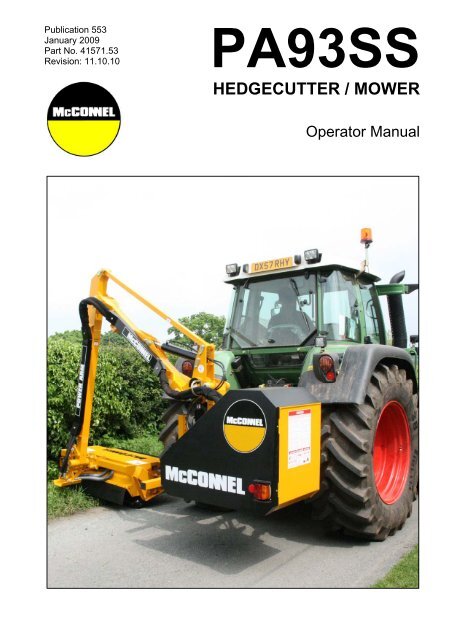
Publication 553January 2009Part No. 41571.53Revision: 11.10.10PA93SSHEDGECUTTER / MOWEROperator Manual
WARRANTY POLICYWARRANTY REGISTRATIONAll machines must be registered, by the selling dealer with <strong>McConnel</strong> Ltd, before delivery to the end user.On receipt of the goods it is the buyer’s responsibility to check that the Verification of Warranty Registrationin the Operator’s Manual has been completed by the selling dealer.1. LIMITED WARRANTIES1.01. All machines supplied by <strong>McConnel</strong> Limited are warranted to be free from defects in material andworkmanship from the date of sale to the original purchaser for a period of 12 months, unless adifferent period is specified.1.02. All spare parts supplied by <strong>McConnel</strong> Limited are warranted to be free from defects in material andworkmanship from the date of sale to the original purchaser for a period of 6 months.1.03. The manufacturer will replace or repair for the purchaser any part or parts found, upon examination atits factory, to be defective under normal use and service due to defects in material or workmanship.Returned parts must be complete and unexamined.1.04. This warranty does not apply to any part of the goods, which has been subjected to improper orabnormal use, negligence, alteration, modification, fitment of non-genuine parts, accident damage, ordamage resulting from contact with overhead power lines, damage caused by foreign objects (e.g.stones, iron, material other than vegetation), failure due to lack of maintenance, use of incorrect oil orlubricants, contamination of the oil, or which has served its normal life. This warranty does not apply toany expendable items such as blades, flails, flap kits, skids, soil engaging parts, shields, guards, wearpads or pneumatic tyres.1.05. Temporary repairs and consequential loss - i.e. oil, downtime and associated parts are specificallyexcluded from the warranty.1.06. Warranty on hoses is limited to 12 months and does not include hoses which have suffered externaldamage. Only complete hoses may be returned under warranty, any which have been cut or repairedwill be rejected.1.07. Machines must be repaired immediately a problem arises. Continued use of the machine after aproblem has occurred can result in further component failures, for which <strong>McConnel</strong> Ltd cannot be heldliable, and may have safety implications.1.08. Except as provided herein, no employee, agent, dealer or other person is authorised to give anywarranties of any nature on behalf of <strong>McConnel</strong> Ltd.1.09. For machine warranty periods in excess of 12 months the following additional exclusions shall apply:1) Hoses, external seals, exposed pipes and hydraulic tank breathers.2) Filters.3) Rubber mountings.4) External electric wiring.N.B. Warranty cover will be invalid if any non-genuine parts have been fitted or used. Use of nongenuineparts may seriously affect the machine’s performance and safety. <strong>McConnel</strong> Ltd. cannot beheld responsible for any failures or safety implications that arise due to the use of non-genuineparts.
2. REMEDIES AND PROCEDURES2.01. The warranty is not effective unless the Selling Dealer registers the machine, via the <strong>McConnel</strong> website and confirms the registration to the purchaser by completing the Verification of WarrantyRegistration in the operator’s manual.2.02. Any fault must be reported to an authorised <strong>McConnel</strong> dealer as soon as it occurs. Continued use of amachine, after a fault has occurred, can result in further component failure for which <strong>McConnel</strong> Ltdcannot be held liable.2.03. Repairs should be undertaken within two days of the failure. Claims submitted for repairs undertakenmore than 2 weeks after a failure has occurred, or 2 days after the parts were supplied will be rejected,unless the delay has been authorised by <strong>McConnel</strong> Ltd.2.04. All claims must be submitted, by an authorised <strong>McConnel</strong> Service Dealer, within 30 days of the date ofrepair.2.05. Following examination of the claim and parts the manufacture will pay, at their discretion, for any validclaim the cost of any parts and an appropriate labour allowance if applicable.2.06. The submission of a claim is not a guarantee of payment.2.07. Any decision reached by <strong>McConnel</strong> Ltd. is final.3. LIMITATION OF LIABILITY3.01. The manufacturer disclaims any express (except as set forth herein) and implied warranties withrespect to the goods including, but not limited to, merchantability and fitness for a particular purpose.3.02. The manufacturer makes no warranty as to the design, capability, capacity or suitability for use of thegoods.3.03. Except as provided herein, the manufacturer shall have no liability or responsibility to the purchaser orany other person or entity with respect to any liability, loss, or damage caused or alleged to be causeddirectly or indirectly by the goods including, but not limited to, any indirect, special, consequential, orincidental damages resulting from the use or operation of the goods or any breach of this warranty.Notwithstanding the above limitations and warranties, the manufacturer’s liability hereunder fordamages incurred by the purchaser or others shall not exceed the price of the goods.3.04. No action arising out of any claimed breach of this warranty or transactions under this warranty may bebrought more than one (1) year after the cause of the action has occurred.4. MISCELLANEOUS4.01. The manufacturer may waive compliance with any of the terms of this limited warranty, but no waiverof any terms shall be deemed to be a waiver of any other term.4.02. If any provision of this limited warranty shall violate any applicable law and is held to be unenforceable,then the invalidity of such provision shall not invalidate any other provisions herein.4.03. Applicable law may provide rights and benefits to the purchaser in addition to those provided herein.
EC DECLARATION OF CONFORMITYConforming to EEC Machinery Directive 98/37/EC*We,McCONNEL LIMITED,Temeside Works, Ludlow, Shropshire SY8 1JL.Declare under our sole responsibility that:The product (type) ……………………………………………………………………Tractor Mounted Hedge Cutter / Trimmer………………………………………………………………………………………….Product Code …………………………………………………………………………..PA93SSSerial No. & Date ……………………………………. Type …………………………Manufactured by the above company/* ………………………………………………………………………………………………………………………………….(* insert business name and full address if not stated above)Complies with the required provisions of the Machinery Directive 98/37/EC, * previouslyDirective 89/392/EEC as amended by Directives 91/368/EEC, 93/44/EEC and 93/68/EEC.The machinery directive is supported by;• BS EN ISO 12100:2003 Safety of Machinery. This standard is made up of two parts;Part 1 Terminology, methodology, Part 2 Technical Specifications.• BS EN 1050 Safety of machinery - Principles of risk assessment.• and other national standards associated with its design and construction as listed inthe Technical File.The Machinery Directive is fully implemented into UK law by means of the Supply ofMachinery (Safety) Regulations 1992 (SI 1992/3073) as amended by The Supply ofMachinery (Safety) (Amendment) Regulations 1994 (SI 1994/2063).Signed …………………………..……………………………………………………...on behalf of McCONNEL LIMITEDResponsible PersonStatus: Chief Design Engineer Date: January 2009
EC DECLARATION OF CONFORMITYConforming to EEC Machinery Directive 98/37/EC*We,McCONNEL LIMITED,Temeside Works, Ludlow, Shropshire SY8 1JL.Declare under our sole responsibility that:The product (type) ……………………………………………………………………Hydraulic Arm Mounted Flailhead………………………………………………………………………………………….Product Code …………………………………………………………………………..BD12, BD16, F110, F112, F115, F012, F016Serial No. & Date ……………………………………. Type …………………………Manufactured by the above company/* ………………………………………………………………………………………………………………………………….(* insert business name and full address if not stated above)Complies with the required provisions of the Machinery Directive 98/37/EC, * previouslyDirective 89/392/EEC as amended by Directives 91/368/EEC, 93/44/EEC and 93/68/EEC.The machinery directive is supported by;• BS EN ISO 12100:2003 Safety of Machinery. This standard is made up of two parts;Part 1 Terminology, methodology, Part 2 Technical Specifications.• BS EN 1050 Safety of machinery - Principles of risk assessment.• and other national standards associated with its design and construction as listed inthe Technical File.The Machinery Directive is fully implemented into UK law by means of the Supply ofMachinery (Safety) Regulations 1992 (SI 1992/3073) as amended by The Supply ofMachinery (Safety) (Amendment) Regulations 1994 (SI 1994/2063).Signed …………………………..……………………………………………………...on behalf of McCONNEL LIMITEDResponsible PersonStatus: Chief Design Engineer Date: January 2009
CONTENTSGeneral Information 1Features 2Safety Information 3Tractor Requirements 9Tractor Preparation 10Initial Attachment 11Machine Attachment 12PTO Driveshaft Installation 16Flailhead Attachment 17Hydraulic Oil 18Running Up Procedure 20Storage 22Operation 23Cable Controls 24Cable Rotor Control 27Electric Switchbox Controls 28Electric Monolever Controls 32XTC Proportional Switchbox Controls 36Breakaway 40Powered Slew 41Moving Into Transport 42Transport Position 43Transport 44Operating Speeds 45Public Highways 46Overhead Power Lines 47Hazards & Dangers 48Hedgecutting Procedure 49Lift Float Kit for Ground Work 50Head Angle Float Kit 51Cooler Kit 52General Maintenance 54Hydraulic System 55Hydraulic Hoses 56Control Cables 57Flail Head 57PTO Shaft Maintenance 58
For Safety and Performance …ALWAYS READ THIS BOOK FIRSTMcCONNEL LIMITEDTemeside WorksLudlowShropshireEnglandTelephone: 01584 873131www.mcconnel.comNOISE STATEMENTThe equivalent daily personal noise exposure from this machine measured at the operators’ ear iswithin the range 78 – 85 dB, these figures apply to a normal distribution of use where the noisefluctuates between zero and maximum. The figures assume that the machine is fitted to a tractor witha ‘quiet’ cab with the windows closed in a generally open environment. We recommend that thewindows are kept closed. With the cab rear window open the equivalent daily personal noiseexposure will increase to a figure within the range 82 – 88 dB. At equivalent daily noise exposurelevels of between 85 – 90 dB ear protection is recommended – it should be used if any window is leftopen.
GENERAL INFORMATIONRead this manual before fitting or operating the machine. Whenever any doubt existscontact your dealer or the <strong>McConnel</strong> Service Department for assistance.Use only <strong>McConnel</strong> Genuine spare parts on <strong>McConnel</strong> equipment and machines.DEFINITIONS: The following definitions apply throughout this manual:WARNING:An operating procedure, technique etc., which can result in personal injury or loss of life ifnot observed carefully.CAUTION:An operating procedure, technique etc., which can result in the damage of either machineor equipment if not observed carefully.NOTE:An operating procedure, technique etc., which is considered essential to emphasize.LEFT AND RIGHT HAND:This term is applicable to the machine when fitted to the tractor and viewed from the rear.This also applies to tractor references.Record the serial number of your machine on this page and always quote this number whenordering spares. Whenever information concerning the machine is requested remember to alsostate the type of tractor to which the machine is fitted.MACHINE SERIAL No.INSTALLATION DATE:MODEL DETAILS:DEALER NAME:DEALER TELEPHONE:DEALER ADDRESS:1
FEATURESPA93SS – all models• Linkage mounted.• Left hand cutting.• Operator guard.• Hydraulic breakaway.• 95° powered slew.• 200 litre hydraulic reservoir.• Choice of 1.2m Supercut/Multicut or 1.5m Super Multicut flailheads.PA93SS Cable models• Totally independent hydraulics powered by tandem PTO pump.• Independent reversible rotor on/off valve.• 54HP hydraulic system.• Cable controls• Head angle float.PA93SS Electric models• Totally independent hydraulics powered by tandem PTO pump.• Independent reversible rotor on/off valve.• Solenoid operated controls.• Choice of ‘Multi switch’ or ‘Joystick’ or ‘XTC Proportional’ controls.• 54HP hydraulic system.Optional Extras• Lift float – All models.• Angle Float – Electric models only.2
This machine has the potential to be extremely dangerous, in the wrong hands it can kill ormaim. It is therefore imperative that both owner, and operator of this machine, read andunderstand the following section to ensure that they are fully aware of the dangers that do,or may exist, and their responsibilities surrounding the use and operation of the machine.The operator of this machine is responsible not only for their own safety but equally for thesafety of others who may come into the close proximity of the machine, as the owner youare responsible for both.When the machine is not in use the cutting head should be lowered to rest on the ground.In the event of a fault being detected with the machine’s operation it should be stoppedimmediately and not used again until the fault has been corrected by a qualified technician.POTENTIAL SIGNIFICANT DANGERS ASSOCIATED WITH THE USE OF THISMACHINE:▲ Being hit by debris thrown by rotating components.▲ Being hit by machine parts ejected through damage during use.▲ Being caught on a rotating power take-off (PTO) shaft.▲ Being caught in other moving parts i.e.: belts, pulleys and cutting heads.▲ Electrocution from Overhead Power Lines (by contact with or ‘flashover’ from).▲ Being hit by cutting heads or machine arms as they move.▲ Becoming trapped between tractor and machine when hitching or unhitching.▲ Tractor overbalancing when machine arm is extended.▲ Injection of high-pressure oil from hydraulic hoses or couplings.▲ Machine overbalancing when freestanding (out of use).▲ Road traffic accidents due to collision or debris on the road.3
BEFORE USING THIS MACHINE YOU MUST:▲ Ensure you read all sections of the operator handbook.▲ Ensure the operator is, or has been, properly trained to use the machine.▲ Ensure the operator has been issued with and reads the operator handbook.▲ Ensure the operator understands and follows the instructions in operator handbook.▲ Ensure the tractor front, rear and side(s) are fitted with metal mesh or polycarbonateguards of suitable size and strength to protect the operator against thrown debris orparts.▲ Ensure tractor guards are fitted correctly, are undamaged and kept properlymaintained.▲ Ensure that all machine guards are in position, are undamaged, and are keptmaintained in accordance with the manufacturer’s recommendations.▲ Ensure flails and their fixings are of a type recommended by the manufacturer, aresecurely attached and that none are missing or damaged.▲ Ensure hydraulic pipes are carefully and correctly routed to avoid damage by chaffing,stretching or pinching and that they are held in place with the correct fittings.▲ Always follow the manufacturer’s instructions for attachment and removal of themachine from the tractor.▲ Check that the machine fittings and couplings are in good condition.▲ Ensure the tractor meets the minimum weight recommendations of the machine’smanufacturer and that ballast is used as necessary.▲ Always inspect the work area thoroughly before starting to note obstacles and removewire, bottles, cans and other debris.▲ Use clear suitably sized warning signs to alert others to the nature of the machineworking within that area. Signs should be placed at both ends of the work site. (It isrecommended that signs used are of a size and type specified by the Department ofTransport and positioned in accordance with their, and the Local Highways Authority,guidelines).▲ Ensure the operator is protected from noise. Ear defenders should be worn and tractorcab doors and windows must be kept closed. Machine controls should be routedthrough proprietary openings in the cab to enable all windows to be shut fully.▲ Always work at a safe speed taking account of the conditions i.e.: terrain, highwayproximity and obstacles around and above the machine. Extra special attention shouldbe applied to Overhead Power Lines. Some of our machines are capable of reach inexcess of 8 metres (26 feet) this means they have the potential to well exceed, bypossibly 3 metres (9’ 9”), the lowest legal minimum height of 5.2 metres from theground for 11,000 and 33,000 volt power lines. It cannot be stressed enough thedangers that surround this capability, it is therefore vital that the operator is fully awareof the maximum height and reach of the machine, and that they are fully conversantwith all aspects regarding the safe minimum distances that apply when working withmachines in close proximity to Power Lines. (Further information on this subject can beobtained from the Health & Safety Executive or your Local Power Company).4
▲ Always disengage the machine, kill the tractor engine, remove and pocket the keybefore dismounting for any reason.▲ Always clear up all debris left at the work area, it may cause hazard to others.▲ Always ensure when you remove your machine from the tractor that it is left in a safeand stable position using the stands and props provided and secured if necessary.WHEN NOT TO USE THIS MACHINE:▲ Never attempt to use this machine if you have not been trained to do so.▲ Never use a machine until you have read and understood the operator handbook, arefamiliar with it, and practiced the controls.▲ Never use a machine that is poorly maintained.▲ Never use a machine if guards are missing or damaged.▲ Never use a machine on which the hydraulic system shows signs of wear or damage.▲ Never fit, or use, a machine on a tractor that does not meet the manufacturer’sminimum specification level.▲ Never use a machine fitted to a tractor that does not have suitable front, rear andside(s) cab guarding made of metal mesh or polycarbonate.▲ Never use the machine if the tractor cab guarding is damaged, deteriorating or badlyfitted.▲ Never turn a machine cutting head to an angle that causes debris to be ejectedtowards the cab.▲ Never start or continue to work a machine if people are nearby or approaching - Stopand wait until they are at a safe distance before continuing. WARNING: Some CuttingHeads may continue to ‘freewheel’ for up to 40 seconds after being stopped.▲ Never attempt to use a machine on materials in excess of its capability.▲ Never use a machine to perform a task it has not been designed to do.▲ Never operate the tractor or machine controls from any position other than from thedriving seat, especially whilst hitching or unhitching the machine.▲ Never carry out maintenance of a machine or a tractor whilst the engine is running –the engine should be switched off, the key removed and pocketed.▲ Never leave a machine unattended in a raised position – it should be lowered to theground in a safe position on a level firm site.▲ Never leave a tractor with the key in or the engine running.▲ Never carry out maintenance on any part or component of a machine that is raisedunless that part or component has been properly substantially braced or supported.▲ Never attempt to detect a hydraulic leak with your hand – use a piece of cardboard.▲ Never allow children near to, or play on, a tractor or machine under any circumstances.5
WARNING!PTO DRIVE SHAFT SAFETY PRECAUTIONSOn Each Tractor Check:▲ Ensure the correct end of the driveshaft is fitted to the tractor. See labels on the driveshaft.▲ Check carefully that the drive shaft does not ‘bottom out’ and that a minimum of 6"(150mm) of engagement is maintained.▲ Ensure that the guards are always in position, can rotate freely and the check chainsare not stretched when the machine is raised or lowered.▲ Check that when, in the continuous working position, the drive shaft is not at an angleof more than 20 degrees to the PTO centre line.▲ Ensure the drive shaft does not foul the tractor PTO guard, the gearbox-input shield orthe tractor draw bar.6
ADDITIONAL SAFETY ADVICETrainingOperators need to be competent and fully capable of operating this machine in a safe andefficient way prior to attempting to use it in any public place. We advise therefore that theprospective operator make use of relevant training courses available such as those run bythe Agricultural Training Board, Agricultural Colleges, Dealers and <strong>McConnel</strong>.Working in Public PlacesWhen working in public places such as roadsides, consideration should be paid to othersin the vicinity. Stop the machine immediately when pedestrians, cyclists and horse ridersetc. pass. Restart only when they are at a distance that causes no risk to their safety.Warning SignsIt is advisable that any working area be covered by suitable warning signs and statutory inpublic places. Signs should be highly visible and well placed in order to give clearadvanced warning of the hazard. Contact the Department of Transport or your LocalHighways Authority to obtain detailed information on this subject. The latter should becontacted prior to working on the public highway advising them of the time and location ofthe intended work asking what is required by way of signs and procedure. – ‘Nonauthorisedplacement of road signs may create offences under the Highways Act’.Suggested Warning Signs Required“Road works ahead” warning sign with a supplementary “Hedge cutting” plate. “For 1mile” or appropriate shorter distance may be added to the plate.“Road narrows” warning sign with supplementary “Single file traffic” plate.White on blue “Keep right” (*) arrow sign on rear of machine.* Note – this applies to UK Market machines where traffic passes to the right of a machine workingin the same direction as the traffic flow. The direction, use and colour of the arrow sign will dependon the country of use and the Local Highway Authorities regulations in the locality.Use of Warning Signs▲ On two-way roads one set of signs is needed facing traffic in each direction.▲ Work should be within 1 mile of the signs.▲ Work only when visibility is good and at times of low risk e.g.: NOT during ‘rush-hour’.▲ Vehicles should have an amber-flashing beacon.▲ Ideally, vehicles should be conspicuously coloured.▲ Debris should be removed from the road and path as soon as practicable, and atregular intervals, wearing high visibility clothing and before removing the hazardwarning signs.▲ Collect all road signs promptly when the job is completed.Although the information given here covers a wide range of safety subjects, it is impossible topredict every eventuality that can occur under differing circumstances whilst operating thismachine. No advice given here can replace ‘good common sense’ and ‘total awareness’ at all times,but will go a long way towards the safe use of your <strong>McConnel</strong> machine.7
FITTING – Tractor requirementsMinimum Tractor Weights - including ballast weight if necessary.All models – 3250 kg.Minimum Hp RequirementsAll models – 60 HPLinkageCategory 2PTO ShaftTractor must be equipped with a live drive PTO to enable forward motion to be stoppedwhile the flail head continues to operate.Linkage IsolationA linkage isolation facility is necessary for Si models only.Check Chains/StabilizersCheck chains or stabilizers must be fitted and tightened.Tractor Relief ValveFor SI models only tractor relief valve must be set above 2000 psi (140 bar).Tractor Hydraulic Flow RateHydraulic flow rates are not crucial for SI models.9
TRACTOR PREPARATIONFitting Tractor Guard: Use tractor withsafety glass windows if possible and fitOperator guard (part no. 73 13 324) usingthe hooks provided. Shape mesh to coverall vulnerable areas. Remember the drivermust be looking through mesh and/orpolycarbonate glazing when viewing theflail head in any working position - unlessthe tractor/cab manufacturer candemonstrate that the penetration resistance is equivalent to, or higher than, that providedby mesh/polycarbonate glazing. If the tractor has a roll bar only, a frame must be made tocarry both mesh and polycarbonate glazing.Wheel Width: Set wheel widths as wide as possible.Lift Links: Adjust lift links until they are equal length.Tractor Ballast: It is imperative when attaching ‘third-party’ equipment to a tractor that themaximum possible stability of the machine and tractor combination is achieved – this canbe accomplished by the utilization of ‘ballast’ in order to counter-balance the additionalequipment added.Front weights may be required to place 15% of total outfit weight on the front axle forstable transport on the road and to reduce ‘crabbing’ due to the drag of the cutting unitwhen working on the ground.Rear weights may be required to maintain a reasonable amount of rear axle load on theopposite wheel from the arms when in work; for normal off-ground work i.e. hedge cuttingthis should be 20% of rear axle weight or more for adequate control, and for ground worki.e. verge mowing with experienced operators, this can be reduced to 10%.All factors must be addressed in order to match the type and nature of the equipmentadded to the circumstances under which it will be used – in the instance of Power ArmHedgecutters it must be remembered that the machines centre of gravity during work willbe constantly moving and will differ from that during transport mode, therefore balancebecomes critical.Factors that effect stability:• Centre of gravity of the tractor/machine combination.• Geometric conditions, e.g. position of the cutting head and ballast.• Weight, track width and wheelbase of the tractor.• Acceleration, braking, turning and the relative position of the cutting head during theseoperations.• Ground conditions, e.g. slope, grip, load capability of the soil/surface.• Rigidity of implement mounting.Suggestions to increase stability:• Increasing rear wheel track; a tractor with a wider wheel track is more stable.• Ballasting the wheel; it is preferable to use external weights but liquid can be added toaround 75% of the tyre volume – water with anti-freeze or the heavier Calcium Chloridealternative can be used.• Addition of weights – care should be taken in selecting the location of the weights toensure they are added to a position that offers the greatest advantage.• Front axle locking; a ram can be used to ‘lock’ the front axle in work only – locking the axlemoves the ‘balance line’ and can be used to transfer weight to the front axle from the rear(check with tractor manufacturer).The advice above is offered as a guide for stability only and is not a guide to tractor strength - it istherefore recommended that you consult your tractor manufacturer or local dealer to obtain specificadvise on this subject, additionally advice should be sought from a tyre specialist with regard to tyrepressures and ratings suitable for the type and nature of the machine you intend to fit.10
INITIAL ATTACHMENT TO TRACTORThe machine will be delivered in a partially dismantled condition, secured with transportstrap and banding.• Choose a firm level site.• Remove the transport strap, bandingstraps and loose items.• Fill tank with oil from the chartor equivalent (see page 18).• Raise the machine using overheadlifting equipment with a minimumcapacity of 1500kg SWL.LEAVE IN POSITION AT THIS STAGE.• Lower the legs and pin in positionselecting the holes that position themachines gearbox stub shaft approx.75 mm below the tractors P.T.O. shaft.Note: Leg pin position used.• Unbolt stabiliser from machine andremove the stabiliser nose quadrant pin.11
MACHINE ATTACHMENTAttachment of the machine should always be performed on a firm level site.CAUTION: During the attachment procedure bystanders must be kept at a safe distancefrom the machine at all times. Never operate the tractors linkage system or machinecontrols when persons are standing on, or working between, the tractor and machine.PTO NOTE: Due to the close coupled design of the machine it is advisable to fit the PTOshaft to the machines gearbox stub axle prior to attaching the machine to the tractor. Oninitial installation the machine will need to be attached without the PTO fitted in order tomeasure for the required shaft length – In some cases the machine will then need to beremoved from the tractor and subsequently refitted with the PTO pre-attached.Attach stabiliser to machine frame at points ‘A’ -selecting a mid-point position initially – securewith nuts and bolts provided. Fit top link atpoints ‘B’ and secure with pins & lock pins.Fit lower link balls and spacers into lower frameconnection points and secure with linkage andlock pins – place spacers to position lower linkballs for best alignment with tractor lower links.Fit PTO shaft to the stub axle of the machinesgearbox. NOTE: for initial installation of a newmachine or attachment to a different tractor referto PTO note at top of page.Adjust the drop arms so that lower links are level.12
312Reverse tractor squarely and centrally to themachine - set tractor lower links to a height thatwill permit attachment to lower frame attachmentpoints.Reverse fully in to attachment points then raisethe tractor linkage until it locks onto the lowerlink balls on both sides of the machine.213Adjust top link to position the stabiliser tonguefor attachment to the tractors top link clevis.NOTE: Alternative tongues for stabilisers areavailable for differing applications.Attach stabiliser tongue to highest suitable clevisposition that does not interfere with or foul tractorcomponents - secure with pin and lock pin.IMPORTANT: Rear of stabiliser tongue should be as close as possible to the bottom of the stabiliserslot with the machine at rest on the ground – if required change the stabiliser lower attachmentpoints and/or clevis attachment position to achieve this setting. This is a vital requirement to ensurethe tongue is located at the slots mid-point when the machine is raised to the work position thusallowing float in each direction.13
Feed control lines into tractor cab – avoid sharpbends and keep lines well clear of all movingparts on the machine or tractor.Connect control lines to the machines controlunit in the tractor cab.Tighten tractor stabilisers - raise tractor linkageto lift the machine to its working height.Attach PTO shaft to the output shaft of thetractor.Attach torque chains to convenient locations toprevent rotation of PTO shaft guarding.14Remove stand legs from both sides of themachine.
Finally, slew the machine into the transportposition, replace slew lock pin (transportmode) and close lift ram tap.Attachment is now complete and themachine ready for transportation to thework site.NOTE:For initial installation refer to running upprocedure.With machine in work position adjust the top linkto bring machine frame into the vertical position.On semi independent machines onlyConnect up the supply and return hoses;Supply – from tractors auxiliary service.Return – to tractors transmission casing (refer to tractor handbook).NOTE: On semi independent machines only select tractors external services.Ensure the Lift Ram tap and Slew Ram taps are open.Request assistanceOperate ‘lift up’ on machine controls sufficient only for the end of the dipper arm to clearthe ground.Pivot out the dipper arm until the tension link can be connected.15
PTO DRIVESHAFT INSTALLATIONThe PTO driveshaft attaches between the tractor and the machine gearbox to transfer thepower required to the run and operate the machine – it is important to achieve the correctshaft length to avoid risk of it ‘bottoming out’ when raising or lowering the machine.The procedure for measuring and cutting the shaft is as follows:Measuring the PTO ShaftWith the machine attached to thetractor in the working position measurethe horizontal distance ‘A’ from thetractor’s PTO to the input shaft on themachines gearbox and subtract 75mm(3”) – this figure is the required shaftlength.Place the fully closed PTO shaft onthe ground and measure its overalllength, if the shaft is shorter than therequired length you can use it withoutthe need to shorten - providing itallows for a minimum 150mm (6”)overlap when fitted.If the shaft is longer subtract therequired shaft length plus an additional75mm (3”) - the resulting figure is theexcess length that will need to beremoved from each half of the shaft.Cutting the PTO ShaftSeparate the two halves and using themeasurement obtained above shortenboth the plastic guarding and the innersteel profile tubes of each shaft by thissame amount. De-burr the cut tubeswith a file to remove rough or sharpedges and thoroughly clean to removeswarf before greasing, assembling andfitting the shaft.NOTE: For subsequent use with different tractors the shaft should be measured again tocheck suitability – there must be a minimum shaft overlap of 150mm (6”).MaintenanceTo increase the working life of the PTO shaft it should be periodically checked, cleanedand lubricated – refer to the PTO maintenance section for further details on this subject.16
FLAILHEAD ATTACHMENTFor ease of attachment and safety this procedure is best performed on a firm level site.With the tractor parked alongside the flailhead operate the controls of the machine toposition the pivot bracket of the machines head angling mechanism directly behindflailhead with the base of the hose tray (or junction bracket) parallel to the ground.Manoeuvre the flailhead backwards on its roller until the heads attachment bracket isadjacent to the machines pivot bracket. Fit the 4 attachment bolts through the bracketsfrom the arm side - if the holes are mis-aligned carefully operate the angling ram until theholes correspond.WARNING: Ensure all persons remain at a safe distance whilst operating the angling function as thegeometry of the head angling mechanism produces several pinch risk areas.With the attachment bolts correctly located through the brackets fit the self-locking nutsand tighten alternately until the brackets are drawn flush before finally tightening them to atorque setting of 203Nm (150ft.lbs).Flailhead Hose AttachmentWith the flailhead attached to themachine the hydraulic hoses cannow be connected – refer todiagrams opposite. Upper port ‘A’on the motor connects to junctionbracket point ‘A’ on the arm andlower port ‘B’ on the motorconnects to junction bracket point‘B’ on the arm.Note: If a hose tray is already fitted tothe arm it will need to be removed toallow the hoses to be connected to thejunction bracket – ensure the hose trayis replaced once the hoses have beenconnected.17
HYDRAULIC OILHydraulic Oil ReservoirFill the tank with oil selected from the chartbelow or a good quality equivalent to a pointwhere the level is between the minimum andmaximum marks on the tank gauge. Whenthe machine is initially run the level will dropas the oil is drawn into the circuit - top backup as required to the correct level on thegauge.Always use clean receptacles when handlingand transferring oil to avoid moisture or dirtcontamination that can damage componentsand/or reduce machine performance.NOTE: Refer to the maintenance section for further information on the subject of hydraulic oil andsystem filtration.Reservoir CapacityThe oil tank capacity of the machine is approximately 200 Litres.Recommended Hydraulic OilsFor initial filling of the oil reservoir, periodic oil changes and replenishment purposes the following hydraulicoils, or a good quality equivalent are recommended:NOTE: Only use oils that are ISO 18/13 or cleaner.Manufacturer Cold or Temperate Climate Hot ClimateBP Bartran 46Energol HLP-HM 46Bartran 68Energol HLP-HM 68CASTROL Hyspin AWH-M 46 Hyspin AWH-M 68COMMA Hydraulic Oil LIC 15 Hydraulic Oil LIC 20ELF Hydrelf HV 46Hydrelf HV 68Hydrelf XV 46ESSO Univis N 46 Univis N 68FUCHS(UK/Non UK markets*)Renolin 46Renolin HVZ 46Renolin CL46/B15*Renolin AF46/ZAF46B*Renolin 68Renolin HVZ 68Renolin CL68/B20*Renolin AF68/ZAF68B*GREENWAY Excelpower HY 68 Excelpower HY 68MILLERS Millmax 46Millmax HV 46MORRIS Liquimatic 5Liquimatic HV 46Triad 46SHELL Tellus 46Tellus T46TEXACO Rando HD 46Rando HDZ 46Millmax 68Millmax HV 68Liquimatic 6Liquimatic HV 68Triad 68Tellus 68Tellus T68Rando HD 68Rando HDZ 68TOTAL Equivis ZS 46 Equivis ZS 6818
FITTING CONTROL UNIT IN CABFitment of the operator controls in the tractor cab will vary depending on the particularmodel or specification of machine – the information below lists the differing methods offitment for the various types of controls available.NOTE: Electric control units work within the range of 12v-16v DC and will require aminimum power supply of 12v DC.Cable ControlsCable control units are provided with, and attached to, a mounting bracket – the bracketshould be securely fixed to the internal mud wing or cab cladding in a suitable convenientlocation that offers ease of use without interfering with normal tractor operation.In deciding the final position of the control unit bear in mind the location of the cable run –make sure the minimum acceptable cable bend radii of 8” (200mm) is not exceeded.Ensure during fitting that no structural member of the tractor cab or roll bar is drilled ordamaged.The cable rotor control valve lever on cable controlled machines will be assembled as acomponent part of the main bank of controls and therefore shares the same mountingbracket.On electric machines with cable operated rotor control valve the lever will be supplied as a‘standalone’ unit with its own individual mounting bracket – this should be fitted in thesame manner as above adopting the same precautions pertaining to attachment and cableruns.Electric ControlsDepending on the particular type of control, electric units are supplied either with amounting bracket or a mounting pillar which should be bolted to the internal mud wing orcab cladding in a suitable convenient location that offers ease of use without interferingwith normal tractor operation. Mounting pillars can be bent or twisted to achieve acomfortable working position. Ensure during fitting that no structural member of the tractorcab or roll bar is drilled or damaged.The power supply cable should be connected directly to the tractors battery - do not usecigarette lighter type connections as these prove to be sporadic and unreliable for controlapplications. Control units are 12 volt DC operated; the brown lead is positive (+) and theblue lead is negative (-).19
RUNNING UP PROCEDURECAUTION! Before initial use of a new machine, all lubrication points must be greasedand the gearbox and oil tank levels checked and where required topped up beforeattempting to use the machine. Refer to maintenance section for details.TI Models onlyEnsure that the rotor control valve is in "STOP" position, start tractor, engage PTO allowthe oil to circulate through the return line filter for about 5 minutes without operation of thearmhead control lever.Operate the armhead levers through their complete range ensuring that all movements arefunctioning correctly.Place the flail head at a safe attitude and move the rotor control to "START" position. Afterinitial fluctuation the rotor should settle to a steady speed. Increase PTO speed toapproximately 360RPM and run for a further five minutes before disengaging and stoppingtractor.Check the hose runs and observe that they are free from any pinching, chaffing, strainingor kinks. Re-check the oil level in the tank-and top up as necessary.SI Models onlyEnsure PTO lever is in neutral position, and isolate tractor hydraulic linkage. Start tractorand select external service supply. Allow the tractor to run for several minutes beforeattempting to operate any of the machine control levers.On operating move the levers through their complete range ensuring that all movementsare functioning correctly.Check the tractor rear axle oil level and top up if necessary.Place the flail head at a safe attitude and bring tractor engine revolutions to 1000RPM.Engage PTO and allow the rotor to run for several minutes. Do not leave the tractor cab orallow anyone to approach the flail head at this time.CAUTION!Do not allow the pump to continue working if the rotor does not turn.Overheating and serious damage to the pump can be caused in a very short time.After running up the machine, increase PTO speed to approximately 360RPM and run fora further five minutes to allow the oil to circulate through the return line filter beforedisengaging the PTO and stopping tractor.Check the hose runs and observe that they are free from any pinching, chafing, strainingor kinks. Re-check the oil level in the tank and top up as necessary.20
REMOVAL FROM TRACTORDANGER!READ CAREFULLY BEFORE COMMENCING TO REMOVE THE MACHINE FROMTHE TRACTOR.THE ORDER OF THE FOLLOWING STEPS MUST BE FOLLOWED EXACTLYDISCONNECTING THE TOP LINK MUST BE THE LAST OPERATION PRIOR TODRIVING THE TRACTOR AWAY FROM THE MACHINE.WARNING!Do not operate quadrant lever or machine controls through the rear cab window whilststanding on or amongst linkage components. Always seek assistance.• Select a firm level site for parking the machine.• Replace parking legs in their sockets and secure in their lowest position.• Raise the machine on the tractor linkage until the weight is taken off the stabiliser.• Remove the lower stabiliser pins.• Unscrew the lift ram tap.• Lower the machine to be ground.• Extend the arms and place the flail head on the ground at half reach.• Disengage tractor PTO and remove.• Disconnect stabiliser bars or loosen check chains as applicable.• Unbolt the control unit from the mounting pillar, remove from tractor cab and stow thelevers or switchbox clear of the ground.• On Si models only disconnect the supply and return hoses and stow with hose endsclear of the ground.• Disconnect the stabiliser from the tractors top hitch position. Allow the stabiliser toslide along the rail until it contacts the eccentric stops.• Remove draft link pins and drive tractor away from machine.21
STORAGEIf machine is to be left standing for an extended period of time, lightly coat the exposedportions of the ram rods with grease. Subsequently this grease should be wiped off beforethe rams are next moved.If the machine has to be stored outside tie a piece of tarpaulin or canvas over the controlassembly, do not use a plastic fertilizer bag which could lead to rapid corrosion.Subsequent Attachment to Identical TractorRefer to and follow steps on ‘initial attachment to tractor’.• Connect stabiliser into tractors top hitch position used previously.• Raise the machine on the tractor linkage until the stabiliser contacts the eccentricstops.• Fit stabiliser lower pins.• Mount controls in the tractor cab.• Fit PTO shaft and attach torque chain to a convenient point to prevent the shaft guardrotating.• Place arms in work position at half reach and adjust lift arm levelling box to bring framehorizontal.• Tighten check chains.• Stow parking legs.• Fold machine into transport position.• Proceed to the work site.Subsequent Attachment to Different Tractor• Remove stabiliser and top link from machine and separate.Refer to and follow steps ‘initial attachment to tractor’.22
OPERATIONOperator GuardPreparationREAD THE BOOK FIRSTPractice operating the machine in an open space without the rotor running until you arefully familiar with the controls and operation of the machine.Tractor ControlsFor Si models only the tractor linkage will need to be isolated.23
CABLE CONTROLSCable controlled machines are supplied with a control unit of the type shown below – theparticular version will be dependent on the specification and features of the machine.Versions differ primarily in the number of armhead control levers assembled within thecontrol bank – some versions will have the rotor control lever assembled alongside thearmhead control levers as shown below left and others will be supplied with the rotorcontrol lever as a ‘standalone’ unit with its own individual mounting bracket.The armhead control levers all move in a forwards and backwards direction eachcontrolling a specific arm function with the exception of the auto reset lever which operatesonly in the backward direction (from central ‘off’ position to the backwards ‘on’ position).Where applicable, if a machine is fitted with the optional lift float feature, operation of thelift float will be via an additional electrical switch which will need to be installed in aconvenient location in the tractor cab.Basic Cable Control UnitCable Control Unit with Auto ResetLOCATION & FUNCTION OF CONTROLS1. Arm Lift Control2. Arm Reach Control3. Head Angle Control / Angle Float Selection4. Arm Slew Control5. Rotor Control6. Auto Reset (where applicable)7. Midcut/VFR (where applicable)24Cable Control Unit with Auto Reset & MidcutNOTE: The illustrations on the following pages show the method of operating all possible functions –depending on individual specifications some features may not be present on your particular machineand therefore will not be applicable.
ARM OPERATIONAutoReset25
Rotor ControlRefer to specific cable rotor control sectionfor additional information on rotor operationMidcut/VFR ModelsFLOAT OPERATION (Angle Float standard/ Lift Float optional)HEAD ANGLE FLOAT -Push angle lever fullyforward into the detentposition.A) Angle Float OFF B) Angle Float ONLift Float (where applicable)A) Lift Float OFF B) Lift Float ON26
CABLE ROTOR CONTROLOn cable rotor control machines the rotor is operated by the lever shown below – from theupright ‘off’ position pushing the lever forward switches the rotor on for downhill cutting andpulling the lever backwards switches the rotor on for uphill cutting. The small pivot lockinglever mounted on the side of the control assembly rotates through 180° to lock the rotor ina specific cutting direction – this is a safety feature to avoid changes of rotor directionwithout first stopping the rotor. To change the direction of cut the rotor lever must beplaced in the upright ‘off’ position; when the rotor has stopped rotating completely the pivotlocking lever can be turned to the opposing position allowing the control lever to beoperated for opposite cutting direction.On some cable operated machines the rotor control lever will be assembled as part of themain bank of controls, whereas on others and all electric models it will be supplied as a‘standalone’ unit with its own mounting bracket.UPHILL CUTTINGLockDOWNHILL CUTTINGLockCAUTION: Ensure the rotor has stopped turning completely before attempting to changedirection - When switched off a rotor can continue to ‘freewheel’ under its own momentumfor up to 40 seconds before stopping.27
ELECTRIC SWITCHBOX CONTROLSMachines with Electric Switchbox Controls will be supplied with one of the control unitsshown below, the particular version will be dependent on the specification of the machine;machines fitted with cable rotor control will use the unit shown left whilst machines withelectric rotor control will use the unit shown right – the only differences between the unitsis that the latter has 2 addition switches fitted for operation of the electric rotor control.Cable Rotor Control Version▼Electric Rotor Control Version▼LOCATION & FUNCTION OF CONTROLS6. Arm Lift Control7. Arm Reach Control8. Flailhead Angle Control9. Arm Slew Control10. Tele/Midcut/VFR Control (Applicable models only)H. Power On/OffI. Auto ResetJ. Head Float - Angle/Lift (Option)K. Rotor On/Off (Electric RCV models)L. Rotor Direction (Electric RCV models)Powering the ControlsActivation of power to the control unit is by operation of switch ‘A’ as shown below:Press the switch down for Power ON (LED light on)Press the switch up for Power OFF (LED light off)PowerONPowerOFF28
ARM OPERATIONAutoResetTele or Midcut/VFR Models only29
HEAD FLOAT OPERATION (Angle Float standard / Lift Float optional)Angle Float OFFLift Float OFFAngle Float OFFLift Float ONAngle Float ONLift Float ONROTOR OPERATION – Electric Rotor Control Models onlyNOTE: The following section relates to machines with Electric Rotor Control only – for Cable RotorControl models refer to the cable rotor control section.Selection of Rotor Cutting DirectionUphill CuttingDownhill Cutting30
Switching the Rotor OnFor safety reasons, to prevent accidental starting of the rotor, the ‘Rotor On’ switch cannotbe activated in a single operation or without first selecting the direction of cut – theprocedure for starting the rotor is as follows:Select the required cutting direction - the Rotor On/Off Switch (D) must then be switchedupwards and held in position for a minimum of 8 seconds before switching it into the fullydown ‘on’ position where it will remain until it is switched off. When the switch is moved tothe down position the red LED light below the switch will be lit to signify the rotor is on – ifthe LED does not light the switch was not held in its up position for long enough and therotor will not have started, repeat the process again holding the switch upwards for alonger period.Rotor StartSwitching the Rotor OffStopping the rotor is performed by switching either the Rotor Power Switch (D) or theRotor Direction Switch (E) to the central (off) position – the red LED light will go out tosignify the rotor has been switched off.Rotor StopCAUTION: When the rotor is switched off it will continue to ‘freewheel’ under its ownmomentum for up to 40 seconds before finally coming to a standstill – do not leave thetractor cab or attempt to approach the flailhead until the rotor has stopped turningcompletely.Alternative Rotor Stop31
ELECTRIC MONOLEVER CONTROLSMachines with Electric Monolever Controls will be supplied with one of the control unitsshown below, the particular version will be dependent on the specification of the machine;machines fitted with cable rotor control will use the unit shown left whilst machines withelectric rotor control will use the unit shown right – the only differences between the unitsis that the latter has 2 addition switches fitted for operation of the electric rotor control.Cable Rotor Control Version▼Electric Rotor Control Version▼LOCATION & FUNCTION OF CONTROLS1. Arm Lift Control2. Arm Reach Control3. Flailhead Angle Control4. Arm Slew Control5. Tele/Midcut/VFR Control (Applicable models only)A. Power On/Off (Emergency Stop)B. Auto ResetC. Head Float - Angle/Lift (Option)D. Rotor On/Off (Electric RCV models)E. Rotor Direction (Electric RCV models)Powering the ControlsActivation of power to the control unit is by operation of switch ‘A’ as shown below:Rotate the switch clockwise to Power ON (LED light on)Press the switch to Power OFF or Emergency Stop (LED light off)PowerONPowerOFF32
ARM OPERATIONAutoResetTele or Midcut/VFR Models only33
HEAD FLOAT OPERATION (Angle Float standard / Lift Float optional)Angle Float OFFLift Float OFFAngle Float OFFLift Float ONAngle Float ONLift Float ONROTOR OPERATION – Electric Rotor Control Models onlyNOTE: The following section relates to machines with Electric Rotor Control only – for Cable RotorControl models refer to the cable rotor control section.Selection of Rotor Cutting DirectionUphill CuttingDownhill Cutting34
Switching the Rotor OnFor safety reasons, to prevent accidental starting of the rotor, the ‘Rotor On’ switch cannotbe activated in a single operation or without first selecting the direction of cut – theprocedure for starting the rotor is as follows:Select the required cutting direction - the Rotor On/Off Switch (D) must then be switchedupwards and held in position for a minimum of 8 seconds before switching it into the fullydown ‘on’ position where it will remain until it is switched off. When the switch is moved tothe down position the red LED light above the switch will be lit to signify the rotor is on – ifthe LED does not light the switch was not held in its up position for long enough and therotor will not have started, repeat the process again holding the switch upwards for alonger period.Rotor StartSwitching the Rotor OffStopping the rotor is performed by switching either the Rotor Power Switch (D) or theRotor Direction Switch (E) to the central (off) position – the red LED light will go out tosignify the rotor has been switched off.Rotor StopCAUTION: When the rotor is switched off it will continue to ‘freewheel’ under its ownmomentum for up to 40 seconds before finally coming to a standstill – do not leave thetractor cab or attempt to approach the flailhead until the rotor has stopped turningcompletely.Alternative Rotor Stop35
XTC (Mk2) PROPORTIONAL SWITCHBOX CONTROLSMachines with XTC Mk2 Proportional Controls (5 service models) will be supplied with thecontrol unit shown below. The units for both electric and cable controlled rotor machinesare identical except that for cable versions the rotor control switches B, C & D (shownbelow) will not provide a function as rotor operation will be controlled by a separate cablelever unit (refer to specific cable rotor control page for operation details of that unit).LOCATION & FUNCTION OF CONTROLS1. Arm Lift Control2. Arm Reach Control3. Head Angle Control4. Arm Slew Control (Default Mode)5. Tele*/Midcut*/VFR* Control (Default Mode)* Applies to the specific model onlyA. Power On/Off (LED ‘a’ indicates status)B. Rotor Start (Uphill Cutting Direction)C. Rotor Start (Downhill Cutting Direction)D. Rotor StopE. Auto ResetF. Head Angle Float On/OffG. Lift Float On/Off (Option)Note: 2 sets of control buttons are installed on each side of the unit for operation of Angle Float &Lift Float, both sets of buttons and their LED’s are linked and therefore perform exactly the samefunction; they are installed to allow for operator preference.LED LightsAn LED light adjacent to each control button reports the status of that particular function –when the function is selected the LED light will illuminate to confirm the function is active;the light will switch off on de-selection of that function.Powering the ControlsActivation of power to the control unit is by operation of the red button switch ‘A’ as shownbelow:Rotate clockwise for Power ON (LED light on)Press for Power OFF / Emergency Stop (LED light off)36
ARM OPERATIONTele or Midcut/VFR Models only37
HEAD FLOAT OPERATIONAngle Float (Standard Feature)Lift Float (Optional Feature)ROTOR OPERATION – Electric Rotor Control Models onlyNOTE: The following section relates to machines with electric rotor control only – for cable rotorcontrol models refer to the specific cable rotor control section.Rotor Start (Selection of Rotor Cutting Direction)Select rotor start for required direction (LED will light to indicate the active direction).Uphill CuttingDownhill Cutting38
Switching Rotor DirectionWith the rotor running, changing the rotor cutting direction can only be achieved after firstoperating ‘rotor stop’, when stop has been selected the specific direction button can thenbe operated to command the rotor to switch to the desired direction. NOTE: This functionhas a built in time delay of approximately 8 seconds - this is a machine protection featurethat allows the rotor sufficient time to de-accelerate before restarting in the oppositedirection. The LED light of the active cutting direction will flash on and off during theslowing down period, when the direction has changed the LED for the new direction will beilluminated.Switching the Rotor OffStopping the rotor is performed by operation of the rotor stop button as illustrated below.When rotor off has been selected the LED light above the button of the active cuttingdirection will flash on and off for approximately 8 seconds to signify that the rotor has beenswitched off, after this 8 second period the light will go off completely. NOTE: The rotor willcontinue to rotate under its own power until it finally comes to a standstill.CAUTION: When the rotor is switched off it will continue to ‘freewheel’ under its ownmomentum for up to 40 seconds before finally coming to a standstill – do not leave thetractor cab or attempt to approach the flailhead until the rotor has stopped turning completely.39
BREAKAWAYThe machine is fitted with a hydraulic breakaway device which protects the structure of themachine should an unforeseen obstacle be encountered.NOTEThe breakaway function does not relieve the operator of his responsibility to drivecarefully, be alert and AVOID OBVIOUS HAZARDS BEFORE CONTACT OCCURS.Breakaway may occur momentarily during normal work should an extra thick or densepatch of vegetation be encountered. In these instances tractor forward motion may bemaintained with care.Where breakaway has occurred as a result of contacting a post or tree etc. the tractormust be halted and the controls of the machine utilised to manoeuvre the head away fromthe obstacle. NEVER CONTINUE FORWARD MOTION TO DRAG THE HEAD AROUNDTHE OBSTACLE IN BREAKBACK POSITION.NOTEThe force required to activate the breakaway system will vary dependent upon thegradient of work. It will require less force when working uphill and vice versa.On mid-cut machines the geometry of the breakaway will cause the head to initially moveoutwards in addition to rearwards. Therefore be aware that the breakaway action will beimpeded if the outer end of the head is working against a steep bank. In this circumstanceextra care must be taken during operation to avoid this occurrence.Breakaway occurs at the slew column pivot. When an obstacle is encountered continuedforward motion causes the pressure in the slew ram base to rise until the relief valvesetting is exceeded.With 'AUTO RESET' selected:When the slew relief valve setting is exceeded oil isdisplaced from the slew ram into the base of the liftram which causes the head to rise as the arm pivotsbackwards to clear the obstruction.Resetting of the head into the work position occursautomatically.With 'SLEW' selected:When the slew relief valve setting is exceeded oil isdisplaced from the slew ram allowing the arm topivot backwards horizontally and the obstacle to becleared.Re-setting the head into the work position is carriedout manually by selecting 'SLEW OUT' on thecontrol assembly40
POWERED SLEWThe slew feature allows a 95° arc of powered arm movement on the working side fromright angles to the tractor to 50 beyond the direct line astern.The feature is required to place the machine in the transport position but can also be usedto sweep the arm to and fro whilst cutting awkward areas and corners thus avoiding theneed to constantly re-position the tractor. To operate in this way 'SLEW' must be selectedon the control assembly.If breakaway occurs the slew motion must be reversed to allow the slew breakaway reliefvalve to re seat and the ram to become operable again.CAUTIONExtra care must be taken when working in 'SLEW’ mode with the reach fully in –IT IS POSSIBLE FOR THE FLAILHEAD TO HIT THE TRACTOR OR MACHINE FRAME.41
MOVING INTO THE TRANSPORT POSITION• Select ‘ROTOR OFF’ and wait until the rotor has stopped turning.• Ensure that the ‘lift’ and ‘angle float’ areswitched off.• Select ‘SLEW’ mode on the controlassembly.• Operate ‘SLEW IN’.• Operate ‘LIFT’ and ‘REACH’ to position themachine (see diagram).• Operate ‘REACH IN’ until the dipper arm contacts thetransport cradle.• Select ‘LIFT UP’ and raise the arms until the tension linkis 300mm from the tractor cab.• Operate ‘ANGLE’ and position the flail head in ascompact position as possible (see transport position).• Fully screw in the lift ram and slew ram taps.42
Shaw, J.D., Gupta, N. & Delery, J.E. (2002). Pay dispersion and workforceperformance: Moderating effects of incentives and interdependence.Strategic Management Journal, 23, 491-512.Simon, H.A. (1978). Rationality as process and as product of thought. AmericanEconomic Review, 68 (May), 1-16.Simon, H.A. (1996). The Sciences of the Artificial (3 rd edition). Cambridge, MA:MIT Press.Simon, H.A. (1997). Administrative Behavior (4 th edition). New York, NY: TheFree Press (Originally published in 1947).Snook, B. Eastwood, J., Gendreau, P., Goggin, C. & Cullen, R.M. (2007). Takingstock of criminal profiling: A narrative review and meta-analysis.Criminal Justice and Behavior, 34, 437-453.Science and Technological Innovation. Washington, DC: Brookings InstitutionPress.Taylor, S.E., & Brown, J. (1988). Illusion and well-being: A social psychologicalperspective on mental health. Psychological Bulletin, 103, 193-210.Timmerman, T.A. (2010). Misconceptions about HRM start early. Journal ofHuman Resources Education, 4, 31-40.Trank, C.Q. & Rynes, S.L. (2003). Who moved our cheese? Reclaimingprofessionalism in business education. Academy of Management Learning& Education, 2, 189-205.238
TRANSPORTWhen in transport the PTO must be disengaged and the power to the control box switchedoff.The acceptable speed of transport will vary greatly depending upon the ground conditions.In any conditions avoid driving at a speed which causes exaggerated bouncing as this willput unnecessary strain on the tractors top hitch position and increase the likelihood of thetension link contacting the cab rear cross member.Transport HeightThere is no fixed dimension for transportheight. It will vary depending on the heightthat the machine is carried and the degreeof arm fold that the rear of the cab willallow.For the majority of installations thetransport height will generally fall betweena minimum of 3.45m and a maximum of3.65m when the machine is correctlyfoldedMoving From Transport to Work Position (All Models)To revert to the work position' the previous procedures for the relevant models are largelyreversed. Remember to unscrew the lift ram tap.Engaging DriveTI ModelsEnsure that the rotor control lever is in the 'Stop’ position before engaging the PTO shaft.Allow the oil to circulate for a minute or so before operating the armhead levers. Positionthe flail head in a safe position, increase the engine speed to a high idle and move rotorcontrol lever to 'START’. After initial surging the rotor will run at an even speed.SI ModelsPlace the flail head at a safe attitude and bring the tractor engine revolutions to 1000RPM.Engage the PTO and slowly increase revs. until operating speeds are attained.44
OPERATING SPEEDSPTO Operating SpeedThe correct PTO speeds for operation of machines are as follows:Gear Machines:500 - 540 rpm (Max)Piston Machines: 800 - 830 rpm (Max)WARNING: Damage to the machine may occur if the maximum PTO speed is exceeded.Engaging DriveEnsure the rotor control lever/switch is in the ‘stop’ position before engaging the PTO.Allow the oil to circulate for a minute or so before operating the armhead controls.Move the flail head into a safe working position just clear of the material to be cut.Increase engine speed to a high idle and start the rotor – after initial ‘surging’ the rotor willrun at an even speed.Carefully lower the flail head into the work area and begin work.Tractor Forward SpeedThe material being cut will determine the tractorforward speed. Forward speed can be as fast asthat which allows the flail head sufficient time to cutthe vegetation both efficiently and neatly.If forward speed is too fast this be indicated by overfrequent operation of the breakaway system, a falloff in tractor revs and a poor untidy finish to thework leaving ragged uncut tufts and poorly mulchedcuttings.‘Running In’ a New MachineFor the first days work with a new machine it isrecommended that tractor forward speed isrestricted to 3 km/hr (2 mph) maximum. This willallow machine components ‘bed in’ and allow theoperator to become familiar with the controls andtheir response under working conditions whilstoperating at a relatively slow speed. If possible,select a first days work that affords mainly light toaverage cutting with occasional heavy duty work –during this period check the tightness of nuts andbolts every hour, retightening as and when required.First day use - check tightness of nuts & bolts hourly ►45
WORKING ON PUBLIC HIGHWAYSWhen working on the public highway it is the operator's responsibility to familiarisehimself with any national and local regulations concerning this type of activity and to abideby them at all times.In addition he must remember that there is a potential for debris to be thrown longdistances should it escape the head shrouds.In inhabited areas work should only proceed with extreme caution and any bystandersmust be kept away from the potential danger area.WARNING!It is the operator’s responsibility to observe these regulations and to keepbystanders at a safe distance.General Working PracticesIt is the operator’s responsibility to develop safe working procedures.Always:• Be aware of hazards in the vicinity.• Make sure all guards are in position and in good condition.• Disengage PTO before stopping the engine.• Wait until the flail has stopped running before leaving the tractor seat.• Disengage the PTO and stop the tractor engine before making any adjustments.• Check frequently that all must and bolts are tight.• Keep bystanders at a safe distance.CUTTING PRECAUTIONS:Inspect the work area, remove any hazardous material and note any immovable obstructions.46
OVERHEAD POWER LINESDANGER!It cannot be stressed enough the dangers involved when working in the vicinity ofoverhead power cables. Some of our machines are capable of reach in excess of 8 metres(26’) therefore they have the potential to well exceed, by possibly 3 metres (9’ 9”), thelowest legal minimum height of 5.2 metres from the ground for 11,000 and 33,000 voltpower lines. Remember electrocution can occur without actually coming into contact with apower line as electricity can ‘flash over’ when machinery gets close to it.Before working in areas where overhead power lines are in close proximity the followingsteps must be observed:• Find out the maximum height and maximum vertical reach of your machine.• Find out the operating voltage of the power lines in the work area - Contact your localelectricity company and/or National Grid Company who will be able to advise you onthe operating voltage and safe minimum clearance distance for working.• Always ensure the safe minimum clearance recommendation is obeyed and work withextreme caution at all times.• If doubt exists do not work in the area – never risk the safety of yourself or others.Emergency Action for Accidents Involving ElectricityNever touch an overhead line - even if it has been brought down by machinery, or hasfallen. Never assume lines are dead.When a machine is in contact with an overhead line, electrocution is possible if anyonetouches both the machine and the ground. Stay in the machine and lower any raised partsin contact or drive the machine out of the lines if you can.If you need to get out to summon help or because of fire, jump out as far as you canwithout touching any wires or the machine - keep upright and away.Get the electricity company to disconnect the supply. Even if the line appears dead, do nottouch it - automatic switching may reconnect the power.Further information and leaflets on this and other agricultural safety subjects are available on the‘Health & Safety Executive’ website at the following address: www.hse.gov.uk/pubns/agindex.htm47
HAZARDS & DANGERSAdverse SlopesWhen working with the flailhead high and reachfully in it is possible for the main arm balance togo over centre and take the weight off the liftram. A restrictor in the gland circuit of the lift ramwill prevent sudden unpredictable movements ifthis should occur - for reasons of safety thisrestrictor should not be removed.DANGER!NEVER REMOVE THE RESTRICTORFROM THE LIFT RAM GLAND CIRCUIT.Never work the machine on adverse slopes with thearms positioned such that the tractor is unbalanced ►DANGER!NEVER CUT TO THE BLIND SIDE OF A HEDGE- it is impossible to see any potential hazards ordangers and the position of the flail head would allowdebris to be propelled through the hedge towards thetractor and operator.DANGER!NEVER OPERATE THE MACHINE WITHTHE FLAIL HEAD ROLLER REMOVEDDANGER!WHEN GRASS MOWING THE ROTOR MUST ALWAYSCUT IN THE UPHILL DIRECTION WITH FRONT HOODFITTED AND THE ROLLER POSITIONED BELOW THECUTTING HEIGHT OF THE FLAILS48
HEDGE CUTTING PROCEDURE1. Cut the side and bottom of the field sidefirst. This leaves the maximum thickness ofhedge on the road side to prevent thepossibility of any debris being thrownthrough the hedge into the path ofoncoming vehicles.2. Cut the side and bottom of the road side.3. Top cut the hedge to the height required.49
LIFT FLOAT KIT (Optional Extra for Ground Cutting)The hydraulic float kit should be mountedto the special bracket in such a positionthat it does not foul any other componentduring the slewing motion.Cable Controlled MachinesOn cable controlled machines the switch is mounted in a convenient location in the cab.The supply cable from the poppet valve solenoid is connected into the tractors ignitionsystem. The brown lead is positive and the blue is negative.Electric Controlled MachinesOn electric controlled machines the cable from the poppet valve solenoid is connected tothe auxiliary switch on the control unit. It is permissible to also have the angle float facilityconnected to the auxiliary switch. In this case both functions will operate in unison.The auxiliary switch on multilever electric controlled machines is a three-position type,which will allow the selection of head float alone, or head and angle float in unison, if bothoptions are fitted.Multilever SwitchboxesFor multilever switchboxes an additional switching kit (Part No. 8402303) is availablewhich, when the dual action position is selected, isolate the lift float function and allowangle float to be selected alone.In work with the solenoid valve open the flailhead will automatically follow the groundcontours. The float action is engaged by selection of the auxiliary switchThe lift control should be operated to take a proportion of the flail head weight off the flailroller. This is important, too little weight on the roller will leave areas of grass while withtoo much weight on the roller the ground will be scalped in places and increased flail wear,damage, or even loss of flails could occur.To revert to standard operation the accumulator(s) is isolated from the lift ram bydeselecting the float switch.50
HEAD ANGLE FLOAT KITThe Head Angle Float is a standard feature on all cable controlled machines and optionalon electric controlled machines – when activated the feature connects the base and glandcircuits of the angle ram to allow free movement of oil in both directions thus allowing thehead to automatically angle itself to match the contours of the ground. Refer to the specificcontrols section for details of operation.Angle Float Off – Requires operator input to adjust flail head angle.Angle Float On – Flail head automatically angles itself to match the ground contours.51
HIGH CAPACITY COOLER KIT (Part No. 7451824)High capacity cooler kits are available where additional cooling of the hydraulic fluid isrequired due to warm and/or humid climates or arduous and demanding workingconditions. Where the cooler is added as an aftermarket fitment it must be fixed to the frontof the main frame in the location of the existing serial number plate – the serial plate willtherefore need to be re-sited to an alternative location on the main frame - it is vital thatthis item is re-fitted to the machine for both security and identification purposes.The procedure for fitting the cooler kit is as follows – the illustrations show the cooler fittedto a left hand build cable TI machine:Installation ProcedureDrill out the pop rivets (Ø3.6mm) that securethe serial number plate to the main frame atlocation ‘A’ - relocate serial number plate tolocation ‘B’.Drill out the 4 existing holes to increase theirdiameter to 11.0mm - bolt the cooler bracketthrough these holes.Note placement of additional washers on the right hand bolt to reduce bolt depth for slew ramclearance - use on opposing bolt where fitment is to R/H build machines.The fitted position should be as shown in thediagrams above.Connect hose from ‘T’ port on the Rotor ControlValve to the Cooler Inlet Pipe52
Cooler Inlet Pipe is located above theThermostat / Fan Control Unit. Connect thePower Loom to tractor auxiliary supply.Connect Cooler Return Pipe to the Filter Returnlocated on the Hydraulic TankComponentsFilter Return Connection on filter housinglocated on the Hydraulic Tank.COOLER COMPONENT IDENTIFICATION1. COOLER BRACKET 12. FLAT WASHER2. OIL COOLER 13. SPRING WASHER3. COOLER LOOM c/w RELAY 14. EDGING STRIP (not shown)4. BONDED SEAL 15. SELF-LOCKING NUT5. SETSCREW 16. HOSE - 1" BSP FS/F90 x 2700mm *6. SELF-LOCKING NUT 17. HOSE - 1" BSP FS/FS 1600mm **7. FLAT WASHER 18. BOLT8. ADAPTOR 19. HYDRAULIC PIPE9. COOLER BASKET 20. ADAPTOR10. STAND OFF 21. BONDED SEAL11. DOME NUT* Cooler Supply Hose (not shown) ** Cooler Return Hose (not shown)NOTE: Depending on the specific machine build, tank fittings 8581425, 8581422, 8600302, 8581110 &8581110 may be required if not already fitted.53
GENERAL MAINTENANCEGeneral LubricationThe example illustration below indicates the general locations of lubrication points - allpoints should be greased on a daily basis and prior storage of the machine. New machinesmust be greased prior to first use.IMPORTANT: Grease newmachines before first use.Gearbox LubricationCheck gearbox oil level on new machines prior to first use, top up if required before using the machine. Refill thegearbox Grease after Points an initial – General 50 hours Locations of use and thereafter at annual or 500 hour intervals, whichever occurs earliest.Gearbox CapacityCast Iron Gearbox – Capacity 0.7 Litre SAE90Drainage of the gearbox forchanges of oil is via the drainplug located on the base ofthe gearbox.For refilling or for ‘topping up’the oil remove both plugsindicated opposite and fillgearbox via the filler plug to apoint where the oil starts torun from the level plug orifice– replace plugs and tightensecurely.54
HYDRAULIC SYSTEMOil SupplyCheck the oil level in the reservoir daily.Oil Condition & ReplacementNo fixed time period can be quoted for oil changes as operating conditions can vary widelybut a visually inspection of the oil will often indicate its current overall state. Signs of areduction in its condition will be apparent by changes in colour and appearance whencompared to new oil. Oil in poor condition can be dark, smell rancid or burnt, or in somecases be yellow, unclear or milky in appearance indicating the presence of air oremulsified water. Moisture resulting from condensation can become entrapped in the oilcausing emulsification that can block the return line filter, consequentially the filter systemwill be by-passed and the oil and any possible contaminants present will continue tocirculate without filtration risking damage to hydraulic components. All are indications orconditions that will require replacement of the oil.Hydraulic oil is a vital component of the machine; contaminated oil is the root cause of70% of all hydraulic system failures. Contamination can be reduced by the following:• Cleaning around the reservoir cap before removal, and keeping the tank area clean.• Use of clean containers when replenishing the system.• Regular servicing of the filtration system.Filtration SystemMachines are protected by both replaceable 125 micron suction strainers and low pressure25 micron full flow return line filters – the diagram below is a ‘scaled up’ view illustratingthe filtering capability built into the hydraulic system of the machine:Filtering CapabilitySuction strainersThe replaceable 125 micron suction strainers (Part No. 8401097) are fitted within thehydraulic tank and are ‘screw’ fitted with easy access for removal and replacement.Return Line FilterThe 25 micron absolute filter elements (Part No. 8401089) should be changed after thefirst 50 hours and thereafter at 500-hour intervals. It is important to note hours worked asif the filter becomes blocked an internal by-pass within the canister will operate and nosymptoms of filter malfunction will occur to jog your memory.Tank BreatherTo reduce the risk of pump cavitation it is advisable to replace the 25 micron absolute tankbreather (Part No. 8401050) on an annual basis under normal working conditions – formachines operating in dry dusty environments it is recommended that replacement beincreased to 6 monthly.55
HYDRAULIC HOSESThe condition of all hoses should be carefully checked during routine service of themachine. Hoses that have been chaffed or damaged on their outer casing should besecurely wrapped with waterproof adhesive tape to stop the metal braid from rusting.Hoses that have suffered damage to the metal braid should be changed at the earliestopportunity.Hose ReplacementBefore changing any hoses take the time to study the existing installation as the routinghas been carefully calculated to prevent hose damage during operation - always replacehoses in exactly the same location and manner. This is especially important for the flailhoses where they must be crossed, upper to lower, at the dipper and head pivots.• Always replace one hose at a time to avoid the risk of wrong connections.• When the hose is screwed to an additional fitting or union, use a second spanner onthe union to avoid breaking both seals.• Do not use jointing compound on the threads.• Avoid twisting the hose. Adjust the hose line to ensure freedom from rubbing ortrapping before tightening hose end connections.All Hydraulic Hoses (BSP) now fitted to <strong>McConnel</strong> Power Arm Hedge/Grass Cutters have‘soft seal’ connections on both flail and ram circuit hoses.Recommended torque settings for nut security are as follows:SIZE TORQUE SETTING O Ring Ref.1/4” BSP = 24 Nm or 18 lb.ft. 10 000 013/8” BSP = 33 Nm or 24 lb.ft. 10 000 021/2” BSP = 44 Nm or 35 lb.ft. 10 000 035/8“ BSP = 58 Nm or 43 lb.ft. 10 000 043/4“ BSP = 84 Nm or 62 lb.ft. 10 000 051” BSP = 115 Nm or 85 lb.ft. 10 000 06For hose unions (BSP) fitted in conjunction with bonded seals the recommended torquesettings are as follows:SIZETORQUE SETTING1/4” BSP = 34 Nm or 25 lb.ft.3/8” BSP = 75 Nm or 55 lb.ft.1/2” BSP = 102 Nm or 75 lb.ft.5/8“ BSP = 122 Nm or 90 lb.ft.3/4“ BSP = 183 Nm or 135 lb.ft.1” BSP = 203 Nm or 150 lb.ft.Safety NoteSoft seal hose connections are capable of holding pressure when the nut is only ‘fingertight’. It is therefore recommended during dismantling that the hose be manually flexed torelieve any residual pressure with the retaining nut slackened prior to completedisassembly.56
CONTROL CABLESThe control cables operate on a push/pull system with the spool centring springs alwaysreturning the spool to the neutral position when the handle is released.Care should be taken during installation and operation to ensure that the cables are nottrapped or kinked. Any abrasion or damage to the outer casing should be sealed withplastic insulation tape to avoid moisture penetrating.No routine adjustments of the cables are necessary, as they do not stretch. The threadedcollar is correctly adjusted when the lever is in a vertical position in its housing allowing anequal amount of travel in either direction.CAUTION!On no account should any attempt be made to lubricate the cables – these are assembled with aspecial ‘lifelong’ lubricant during manufacture and will not require any additional lubrication.Note: Take care to ascertain the correct cable connections on both the control unit and thevalve in the event of cable replacement.FLAIL HEADFrequently inspect the rotor assembly for damaged or missing flails. Bolts and nutssecuring the flails to the rotor should be regularly checked and kept tight. The correcttorque setting for these locknuts is 135Nm (100 Ibf/ft.). Use only the correct flail bolt andlocking nut. Check the flail pivot bushes for possible damage or wear - they do not requireoil.Do not attempt to run the rotor with flails missing. Imbalance will cause severe vibrationand can rapidly damage the rotor shaft bearings. As an emergency measure if a flail isbroken off or lost, remove another on the opposite side of the rotor to retain balance.Always replace flails in opposite pairs and never match up a new flail with a re-sharpenedone, which will of course be lighter.Blunt flails absorb a lot of power and leave an untidy finish to the work. They should besharpened on a grindstone or with a portable grinder periodically.WARNING!Wear protective gear when sharpening flails.Ensure that the bearing housings and hydraulic mounting nuts and bolts are kept tight.They should be checked during servicing.57
PTO SHAFT MAINTENANCEPTO Shaft LubricationThe PTO shaft should be lubricated on a regular basis using lithium based grease – eachend of the shaft has 2 greasing points; one for lubrication of the universal joint and one forlubricating the rotating fixing ring of the shaft shield – access to the lubrication points isgained by releasing the shaft shield from its fixing ring and sliding it back along the body ofthe driveshaft – the procedure and lubrication frequency is illustrated below.Shaft shield fixing claspsInsert screwdrivers into the claspsPrise clasps open to release the shieldSlide shield back to reveal universal jointPTO Shaft ShieldLubrication PointUniversal JointLubrication PointLocation of lubrication pointsRecommended lubricating frequencySlide the shaft shield back into place after lubrication ensuring the clasps relocate correctlyin the fixing ring – always fit torque chains to the shields to stop them from rotating with theshaft during operation.58
<strong>McConnel</strong> Limited, Temeside Works, Ludlow, Shropshire SY8 1JL. England.Telephone: 01584 873131. Facsimile: 01584 876463. www.mcconnel.com


