High-Performance Micro-D Connectors and Cables - Pan Pacific ...
High-Performance Micro-D Connectors and Cables - Pan Pacific ...
High-Performance Micro-D Connectors and Cables - Pan Pacific ...
- No tags were found...

You also want an ePaper? Increase the reach of your titles
YUMPU automatically turns print PDFs into web optimized ePapers that Google loves.
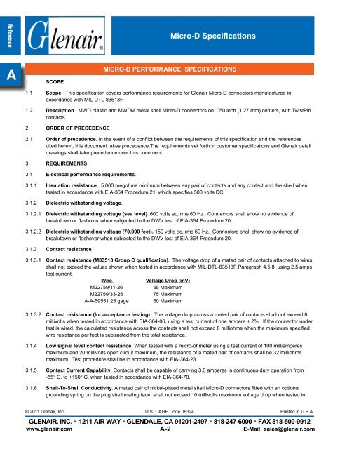
Reference<strong>Micro</strong>-D SpecificationsA1 SCOPEmicro-d performance specifications1.1 Scope. This specification covers performance requirements for Glenair <strong>Micro</strong>-D connectors manufactured inaccordance with MIL-DTL-83513F.1.2 Description. MWD plastic <strong>and</strong> MWDM metal shell <strong>Micro</strong>-D connectors on .050 inch (1.27 mm) centers, with TwistPincontacts.2 ORDER OF PRECEDENCE2.1 Order of precedence. In the event of a conflict between the requirements of this specification <strong>and</strong> the referencescited herein, this document takes precedence.The requirements set forth in customer specifications <strong>and</strong> Glenair detaildrawings shall take precedence over this document.3 REQUIREMENTS3.1 Electrical performance requirements.3.1.1 Insulation resistance. 5,000 megohms minimum between any pair of contacts <strong>and</strong> any contact <strong>and</strong> the shell whentested in accordance with EIA-364 Procedure 21, which specifies 500 volts DC.3.1.2 Dielectric withst<strong>and</strong>ing voltage.3.1.2.1 Dielectric withst<strong>and</strong>ing voltage (sea level). 600 volts ac, rms 60 Hz. <strong>Connectors</strong> shall show no evidence ofbreakdown or flashover when subjected to the DWV test of EIA-364 Procedure 20.3.1.2.2 Dielectric withst<strong>and</strong>ing voltage (70,000 feet). 150 volts ac, rms 60 Hz. <strong>Connectors</strong> shall show no evidence ofbreakdown or flashover when subjected to the DWV test of EIA-364 Procedure 20.3.1.3 Contact resistance3.1.3.1 Contact resistance (M83513 Group C qualification). The voltage drop of a mated pair of contacts attached to wiresshall not exceed the values shown when tested in accordance with MIL-DTL-83513F Paragraph 4.5.8, using 2.5 ampstest current.WireVoltage Drop (mV)M22759/11-2665 MaximumM22759/33-2675 MaximumA-A-59551 25 gage 60 Maximum3.1.3.2 Contact resistance (lot acceptance testing). The voltage drop across a mated pair of contacts shall not exceed 8millivolts when tested in accordance with EIA-364-06, using a test current of one ampere ± 2%. If the connector undertest is wired, the calculated resistance across the contacts shall not exceed 8 milliohms when the maximum specifiedwire resistance per foot is subtracted from the total resistance.3.1.4 Low signal level contact resistance. When tested with a micro-ohmeter using a test current of 100 milliamperesmaximum <strong>and</strong> 20 millivolts open circuit maximum, the resistance of a mated pair of contacts shall be 32 milliohmsmaximum. Test procedure shall be in accordance with EIA-364-23.3.1.5 Contact Current Capability. Contacts shall be capable of carrying 3.0 amperes in continuous duty operation from-55° C. to +150° C. when tested in accordance with EIA-364-70.3.1.6 Shell-To-Shell Conductivity. A mated pair of nickel-plated metal shell <strong>Micro</strong>-D connectors fitted with an optionalgrounding spring on the plug shell mating face, shall not exceed 10 millivolts maximum voltage drop when tested in© 2011 Glenair, Inc. U.S. CAGE Code 06324Printed in U.S.A.GLENAIR, INC. • 1211 AIR WAY • GLENDALE, CA 91201-2497 • 818-247-6000 • FAX 818-500-9912www.glenair.comA-2E-Mail: sales@glenair.com