Thermal Modeling and Analysis of Device-Contactor ... - Johnstech
Thermal Modeling and Analysis of Device-Contactor ... - Johnstech
Thermal Modeling and Analysis of Device-Contactor ... - Johnstech

Create successful ePaper yourself
Turn your PDF publications into a flip-book with our unique Google optimized e-Paper software.
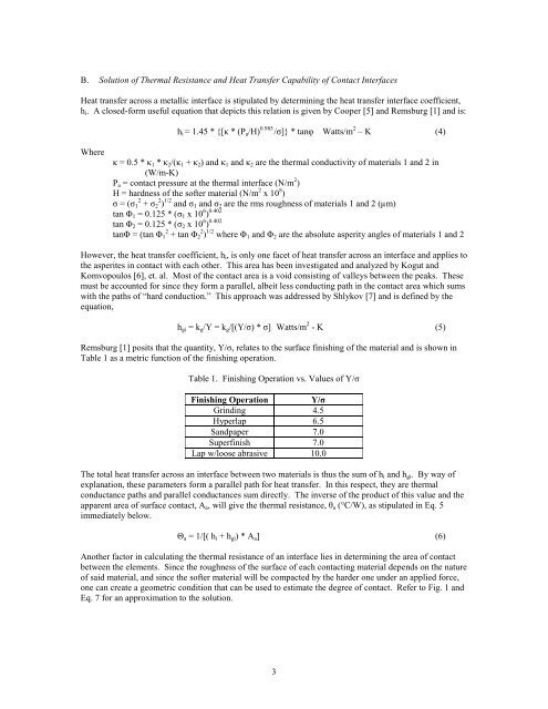
B. Solution <strong>of</strong> <strong>Thermal</strong> Resistance <strong>and</strong> Heat Transfer Capability <strong>of</strong> Contact InterfacesHeat transfer across a metallic interface is stipulated by determining the heat transfer interface coefficient,h i . A closed-form useful equation that depicts this relation is given by Cooper [5] <strong>and</strong> Remsburg [1] <strong>and</strong> is:h i = 1.45 * {[κ * (P a /H) 0.985 /σ]} * tanφ Watts/m 2 – K (4)Whereκ = 0.5 * κ 1 * κ 2 /(κ 1 + κ 2 ) <strong>and</strong> κ 1 <strong>and</strong> κ 2 are the thermal conductivity <strong>of</strong> materials 1 <strong>and</strong> 2 in(W/m-K)P a = contact pressure at the thermal interface (N/m 2 )H = hardness <strong>of</strong> the s<strong>of</strong>ter material (N/m 2 x 10 8 )σ = (σ 1 2 + σ 2 2 ) 1/2 <strong>and</strong> σ 1 <strong>and</strong> σ 2 are the rms roughness <strong>of</strong> materials 1 <strong>and</strong> 2 (µm)tan Φ 1 = 0.125 * ( σ 1 x 10 6 ) 0.402tan Φ 2 = 0.125 * ( σ 2 x 10 6 ) 0.402tanΦ = (tan Φ 1 2 + tan Φ 2 2 ) 1/2 where Φ 1 <strong>and</strong> Φ 2 are the absolute asperity angles <strong>of</strong> materials 1 <strong>and</strong> 2However, the heat transfer coefficient, h i , is only one facet <strong>of</strong> heat transfer across an interface <strong>and</strong> applies tothe asperites in contact with each other. This area has been investigated <strong>and</strong> analyzed by Kogut <strong>and</strong>Komvopoulos [6], et. al. Most <strong>of</strong> the contact area is a void consisting <strong>of</strong> valleys between the peaks. Thesemust be accounted for since they form a parallel, albeit less conducting path in the contact area which sumswith the paths <strong>of</strong> “hard conduction.” This approach was addressed by Shlykov [7] <strong>and</strong> is defined by theequation,h gi = k g /Y = k g /[(Y/σ) * σ] Watts/m 2 - K (5)Remsburg [1] posits that the quantity, Y/σ, relates to the surface finishing <strong>of</strong> the material <strong>and</strong> is shown inTable 1 as a metric function <strong>of</strong> the finishing operation.Table 1. Finishing Operation vs. Values <strong>of</strong> Y/σFinishing Operation Y/σGrinding 4.5Hyperlap 6.5S<strong>and</strong>paper 7.0Superfinish 7.0Lap w/loose abrasive 10.0The total heat transfer across an interface between two materials is thus the sum <strong>of</strong> h i <strong>and</strong> h gi . By way <strong>of</strong>explanation, these parameters form a parallel path for heat transfer. In this respect, they are thermalconductance paths <strong>and</strong> parallel conductances sum directly. The inverse <strong>of</strong> the product <strong>of</strong> this value <strong>and</strong> theapparent area <strong>of</strong> surface contact, A a , will give the thermal resistance, θ a (°C/W), as stipulated in Eq. 5immediately below.Θ a = 1/[( h i + h gi ) * A a ] (6)Another factor in calculating the thermal resistance <strong>of</strong> an interface lies in determining the area <strong>of</strong> contactbetween the elements. Since the roughness <strong>of</strong> the surface <strong>of</strong> each contacting material depends on the nature<strong>of</strong> said material, <strong>and</strong> since the s<strong>of</strong>ter material will be compacted by the harder one under an applied force,one can create a geometric condition that can be used to estimate the degree <strong>of</strong> contact. Refer to Fig. 1 <strong>and</strong>Eq. 7 for an approximation to the solution.3