Thermal Modeling and Analysis of Device-Contactor ... - Johnstech
Thermal Modeling and Analysis of Device-Contactor ... - Johnstech
Thermal Modeling and Analysis of Device-Contactor ... - Johnstech

Create successful ePaper yourself
Turn your PDF publications into a flip-book with our unique Google optimized e-Paper software.
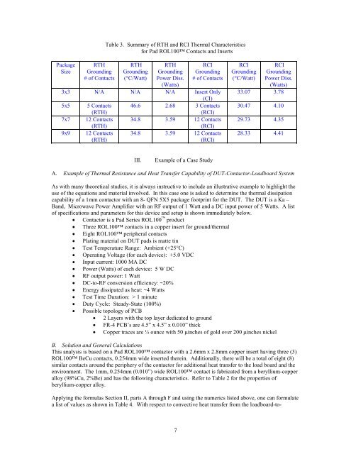
Table 3. Summary <strong>of</strong> RTH <strong>and</strong> RCI <strong>Thermal</strong> Characteristicsfor Pad ROL100 Contacts <strong>and</strong> InsertsPackageSizeRTHGrounding# <strong>of</strong> ContactsRTHGrounding(°C/Watt)RTHGroundingPower Diss.(Watts)RCIGrounding# <strong>of</strong> Contacts3x3 N/A N/A N/A Insert Only(CI)5x5 5 Contacts 46.6 2.68 3 Contacts(RTH)(RCI)7x7 12 Contacts 34.8 3.59 12 Contacts(RTH)(RCI)9x9 12 Contacts 34.8 3.59 12 Contacts(RTH)(RCI)RCIGrounding(°C/Watt)RCIGroundingPower Diss.(Watts)33.07 3.7830.47 4.1029.73 4.3528.33 4.41III.Example <strong>of</strong> a Case StudyA. Example <strong>of</strong> <strong>Thermal</strong> Resistance <strong>and</strong> Heat Transfer Capability <strong>of</strong> DUT-<strong>Contactor</strong>-Loadboard SystemAs with many theoretical studies, it is always instructive to include an illustrative example to highlight theuse <strong>of</strong> the equations <strong>and</strong> material involved. In this case one is asked to determine the thermal dissipationcapability <strong>of</strong> a 1mm contactor with an 8- QFN 5X5 package footprint for the DUT. The DUT is a Ka –B<strong>and</strong>, Microwave Power Amplifier with an RF output <strong>of</strong> 1 Watt <strong>and</strong> a DC input power <strong>of</strong> 5 Watts. A list<strong>of</strong> specifications <strong>and</strong> parameters for this device <strong>and</strong> setup is shown immediately below.• <strong>Contactor</strong> is a Pad Series ROL100 product• Three ROL100 contacts in a copper insert for ground/thermal• Eight ROL100 peripheral contacts• Plating material on DUT pads is matte tin• Test Temperature Range: Ambient (+25°C)• Operating Voltage (for each device): +5.0 VDC• Input current: 1000 MA DC• Power (Watts) <strong>of</strong> each device: 5 W DC• RF output power: 1 Watt• DC-to-RF conversion efficiency: ~20%• Energy dissipated as heat: ~4 Watts• Test Time Duration: > 1 minute• Duty Cycle: Steady-State (100%)• Possible topology <strong>of</strong> PCB• 2 Layers with the top layer dedicated to ground• FR-4 PCB’s are 4.5” x 4.5” x 0.010” thick• Copper traces are ½ ounce with 50 µinches <strong>of</strong> gold over 200 µinches nickelB. Solution <strong>and</strong> General CalculationsThis analysis is based on a Pad ROL100 contactor with a 2.6mm x 2.8mm copper insert having three (3)ROL100 BeCu contacts, 0.254mm wide inserted therein. Additionally, there will be a total <strong>of</strong> eight (8)similar contacts around the periphery <strong>of</strong> the contactor for additional heat transfer to the load board <strong>and</strong> theenvironment. The 1mm, 0.254mm (0.010”) wide ROL100 contact is fabricated from a beryllium-copperalloy (98%Cu, 2%Be) <strong>and</strong> has the following characteristics. Refer to Table 2 for the properties <strong>of</strong>beryllium-copper alloy.Applying the formulas Section II, parts A through F <strong>and</strong> using the numerics listed above, one can formulatea list <strong>of</strong> values as shown in Table 4. With respect to convective heat transfer from the loadboard-to-7