Δ sh iL irθ/2Fig.1. Interface Geometry to Determine Contact AreaL i = 2 * (2*h i *r – h 2 i ) 1/2 meters (7)Wherer = radius <strong>of</strong> contacting surface in metersh i = average surface roughness <strong>of</strong> s<strong>of</strong>ter material in metersIt follows that the apparent area <strong>of</strong> contact is the product <strong>of</strong> L i <strong>and</strong> the width <strong>of</strong> the contact. There are twointerfaces for a DUT in a contactor, namely one between the pads or leads <strong>of</strong> the device <strong>and</strong> the contact <strong>and</strong>the other between the contact <strong>and</strong> the loadboard pads. Therefore, the overall thermal resistance, R θ,contact-Ifs ,<strong>of</strong> a contact is given as:R θ,contact-Ifs = R θ,contact + R θ,IF1 + R θ,IF2 °C/W (8)WhereR θ,IF1 = thermal resistance <strong>of</strong> IF1 contact in (°C/W)R θ,IF2 = thermal resistance <strong>of</strong> IF2 contact in (°C/W)C. Solution <strong>of</strong> <strong>Thermal</strong> Resistance <strong>and</strong> Heat Transfer Capability <strong>of</strong> <strong>Thermal</strong> Ground Insert <strong>and</strong> itsInterfacesHeat transfer from the thermal pad <strong>of</strong> the DUT to the loadboard <strong>and</strong> thence to the environment is viaconduction. From a practical st<strong>and</strong>point, the most effective economical material to use is copper which hasthe second highest thermal conductivity next to silver (the highest). Table 2 lists some typical properties <strong>of</strong>metals, or in the case <strong>of</strong> beryllium-copper (alloy), used as wire materials.Table 2. Typical Properties <strong>of</strong> MetalsProperty Copper Gold Beryllium-CopperMelting Point, T m 1,083°C 1063°C 980°C<strong>Thermal</strong> Conductivity, κ @ 20°C 394 W/m-K 294 W/m-K 95 W/m-KDensity, ρ 8,950 Kg/m 3 19,300 Kg/m 3 8,321.4 Kg/m 3Electrical Resistivity, ρ e @ 20°C 1.65x10 -8 Ω-m 2.19x10 -8 Ω-m 7.68x10 -8 Ω-m<strong>Thermal</strong> Coef. Of Resistivity, α 0.0043 1/C 0.0040 1/C 0.0010 1/CSpecific Heat, c p 385 J/Kg-K 129 J/Kg-K 418.7 J/Kg-KElectrical Conductivity @ 20°C 59.9x10 6 1/Ω-m 45.7x10 6 1/Ω-m 13.0x10 6 1/Ω-mThe equations shown in Section II, parts A <strong>and</strong> B <strong>of</strong> this paper are directly applicable <strong>and</strong> can be used tosolve for the electrical <strong>and</strong> thermal resistance <strong>of</strong> the ground insert. The methodology used to determine thecontact interface between the DUT thermal pad <strong>and</strong> the insert <strong>and</strong> between the insert <strong>and</strong> the loadboardpads also applies. If contacts are used in the ground insert, then allowance must be made for the volume <strong>of</strong>material removed, per slot, <strong>and</strong> for the reduction in contact surface area. The total thermal resistance <strong>of</strong> theground insert <strong>and</strong> its accompanying interfaces is the sum <strong>of</strong> their numeric values <strong>and</strong> is…4
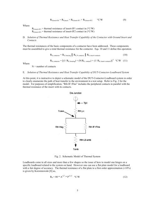
R θ,insert-Ifs = R θ,insert + R θ,insert-IF1 + R θ,insert-IF2 °C/W (9)WhereR θ,insert-IF1 = thermal resistance <strong>of</strong> insert-IF1 contact in (°C/W)R θ,insert-IF2 = thermal resistance <strong>of</strong> insert-IF2 contact in (°C/W)D. Solution <strong>of</strong> <strong>Thermal</strong> Resistance <strong>and</strong> Heat Transfer Capability <strong>of</strong> the <strong>Contactor</strong> with Ground Insert <strong>and</strong>ContactsThe thermal resistances <strong>of</strong> the basic components <strong>of</strong> a contactor have been addressed. These componentsmust be assembled to give a total thermal resistance for the contactor. Eqs. 10 <strong>and</strong> 11 define this operation.R θ, contactor = R θ, housing ║ R θ, N contacts ║ R θ, insert+contacts (10)WhereN = number <strong>of</strong> contactsR θ, contactor = [(1/ R θ, housing ) + (N/R θ, contact ) + (1/ R θ, insert+contacts )] -1 °C/W (11)E. Solution <strong>of</strong> <strong>Thermal</strong> Resistance <strong>and</strong> Heat Transfer Capability <strong>of</strong> DUT-<strong>Contactor</strong>-Loadboard SystemAt this point, it is instructive to depict a schematic model <strong>of</strong> the DUT-<strong>Contactor</strong>-Loadboard system in orderto clearly enumerate the path <strong>of</strong> heat transfer to the environment in a test setup. Refer to Fig. 2 for themodel. For purposes <strong>of</strong> simplification, “Rth IF+Pins” includes the peripheral contacts in parallel with thethermal resistance <strong>of</strong> the insert with its contacts.Fig. 2. Schematic Model <strong>of</strong> <strong>Thermal</strong> SystemLoadboards come in all sizes <strong>and</strong> more than a few shapes so the issue <strong>of</strong> how to model one hinges on aspecific loadboard related to the system on h<strong>and</strong>. However one can use a flat plate model for a loadboardwith a fair degree <strong>of</strong> accuracy. The thermal resistance <strong>of</strong> a flat plate to a first order approximation (±10%)is given by Korzeniowski [8] as,R θ = 80 * A -0.7 * P -0.15 °C/W (12)5