Integrating Digiquartz MET3 and MET3A ... - Paroscientific, Inc.
Integrating Digiquartz MET3 and MET3A ... - Paroscientific, Inc.
Integrating Digiquartz MET3 and MET3A ... - Paroscientific, Inc.

You also want an ePaper? Increase the reach of your titles
YUMPU automatically turns print PDFs into web optimized ePapers that Google loves.
<strong>Paroscientific</strong>, <strong>Inc</strong>.Technical NotePrecision Pressure Instrumentation Doc. No. G8036 Rev. NC 25 November 2003<strong>Integrating</strong> <strong>Digiquartz</strong> ® <strong>MET3</strong> <strong>and</strong> <strong>MET3</strong>ABroadb<strong>and</strong> Meteorological Systemswith a Trimble NetRS GPS Receiver“The st<strong>and</strong>ard by which other st<strong>and</strong>ards are measured”<strong>Paroscientific</strong>, <strong>Inc</strong>.4500 148 th Ave. N.E.Redmond, WA 98052, USATel: (425) 883-8700 Fax: (425) 867-5407www.paroscientific.comsupport@paroscientific.com©2003 <strong>Paroscientific</strong>, <strong>Inc</strong>.
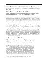
<strong>Paroscientific</strong>, <strong>Inc</strong>.Technical NotePrecision Pressure Instrumentation Doc. No. G8036 Rev NC 25 November 2003<strong>Integrating</strong> <strong>Digiquartz</strong> ® <strong>MET3</strong> <strong>and</strong> <strong>MET3</strong>ABroadb<strong>and</strong> Meteorological Systemswith a Trimble NetRS GPS ReceiverByMustafa Yilmazsupport@paroscientific.com1. Introduction<strong>Paroscientific</strong>’s <strong>MET3</strong> <strong>and</strong> <strong>MET3</strong>A Broadb<strong>and</strong> Meteorological Measurement Systems were specifically designedfor GPS-Meteorology <strong>and</strong> geophysical applications. For both of these applications, it is necessary to calculate theamount of precipitable water vapor (PWV) in the atmosphere for very accurate position measurements or short-termweather forecasts (nowcasting). For these applications, precision, accuracy, reliability, <strong>and</strong> long-term stability of theMET stations correspond to low total cost-of-ownership in the long run. The broadb<strong>and</strong> feature of these instrumentsalso enables scientists to measure other atmospheric <strong>and</strong> geophysical signals with a network of GPS receivers colocatedwith <strong>Digiquartz</strong>® <strong>MET3</strong> <strong>and</strong> <strong>MET3</strong>A Meteorological Measurement Systems.The purpose of this document is to provide specific integration <strong>and</strong> diagnostics information, additional to the <strong>MET3</strong><strong>and</strong> <strong>MET3</strong>A User’s Manual, to facilitate the integration of a MET station with a Trimble NetRS GPS receiver.Once the MET stations are set up properly in the field, these instruments are designed to work under ruggedenvironmental conditions for years without problems.The operating principle of a MET station with a GPS receiver is simple <strong>and</strong> relies on a few critical parameters. Thistechnical paper elaborates on these critical parameters <strong>and</strong> provides a technical recipe to integrate a Trimble NetRSGPS receiver with a MET station.Since surface pressure <strong>and</strong> temperature measurements are vital parameters for PWV calculations, the data reliability<strong>and</strong> integrity from the MET stations are of paramount importance.2. <strong>MET3</strong> & <strong>MET3</strong>A Broadb<strong>and</strong> Meteorological Systems Performance SummaryThe <strong>MET3</strong> <strong>and</strong> <strong>MET3</strong>A precision measurement instruments provide high accuracy data from barometric pressure,temperature, <strong>and</strong> relative humidity sensors. Pressure resolution is better than 1 microbar with a total accuracy of±0.08 hPa over the extended barometric range of 620 to 1100 hPa. Temperature resolution is 0.01 degree C. Thefan-aspirated <strong>MET3</strong>A has a total temperature accuracy of 0.1 degree C over the operating temperature range of –50to +60 degrees C. Relative humidity performance is better than 2% at 25 degrees C, <strong>and</strong> humidity recovery time forthe <strong>MET3</strong>A after 100% water saturation is less than 2 minutes.These fully integrated systems are housed in environmental enclosures allowing st<strong>and</strong>-alone, indoor or outdoormounting. Installation hardware <strong>and</strong> software are included, <strong>and</strong> optional interface cabling is available for easysystem integration. The <strong>MET3</strong> radiation shield protects the temperature <strong>and</strong> humidity sensors from precipitation<strong>and</strong> solar radiation. The <strong>MET3</strong>A utilizes a high performance, tuned barometric pressure port to reduce dynamicpressure errors caused by wind.Microprocessor-based electronics provide fully temperature compensated <strong>and</strong> linearized outputs via a two-way RS-232 interface. The serial interface allows complete remote configuration <strong>and</strong> control of all operating parametersincluding resolution, sample rates, choice of engineering units, integration time, <strong>and</strong> sampling comm<strong>and</strong>s. Individualmeasurement parameters or a “unified” data word with all sensor outputs are easily interfaced with computersystems, GPS receivers, <strong>and</strong> data loggers.©2003 <strong>Paroscientific</strong>, <strong>Inc</strong>. 2
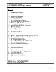
<strong>Paroscientific</strong>, <strong>Inc</strong>.Technical NotePrecision Pressure Instrumentation Doc. No. G8036 Rev NC 25 November 20033. What do you need for GPS-MET Integration?Purchase of Trimble NetRS <strong>and</strong> a Broadb<strong>and</strong> <strong>Digiquartz</strong>® <strong>MET3</strong> or <strong>MET3</strong>A Meteorological package shouldinclude the following items from each vendor. If any of these items are missing from your package, please contactTrimble or <strong>Paroscientific</strong>, <strong>Inc</strong>.GPS ReceiverGPS Antenna (comes with cable)Ethernet Cable RS-232 Service Cable Power & Ethernet Port Power AdapterTable 1. Items provided by TrimbleMET StationMET Cable (optional)Power breakout/supply kit (optional)<strong>Digiquartz</strong>® Software CDTable 2. Items provided by <strong>Paroscientific</strong>©2003 <strong>Paroscientific</strong>, <strong>Inc</strong>. 3
<strong>Paroscientific</strong>, <strong>Inc</strong>.Technical NotePrecision Pressure Instrumentation Doc. No. G8036 Rev NC 25 November 20034. Operating Principle of MET StationsMET stations include the world’s most accurate, stable, <strong>and</strong> reliable Broadb<strong>and</strong> <strong>Digiquartz</strong>® Barometers,environmentally packaged with a precision temperature <strong>and</strong> humidity probe. Integral electronics <strong>and</strong> integrated,compact packaging make installation <strong>and</strong> communication with these instruments an easy task.In order for a MET station to work with any GPS receiver, regardless of the GPS receiver manufacturer, thefollowing conditions must be met.a. The MET instrument must be powered up.<strong>Paroscientific</strong> MET stations require a power source providing a voltage output of +7 to +16 VDC through pin 9 ofits RS-232 connector. Some GPS receivers (e.g. Thales) provide power on pin 9 of the RS-232 cable. TrimbleNetRS does not provide power through its communication ports. So, you have to use the power adapter kitoptionally supplied by <strong>Paroscientific</strong>, <strong>Inc</strong>. If you don’t have this kit, please contact <strong>Paroscientific</strong> Sales <strong>and</strong>Application engineers to get the power breakout/ supply kit (Part Number 1727-00X: X=1 for 110 VAC, for 220VAC X=2). You may order this kit during your purchase of the MET station as well.Note: MET stations shipped after 8/02 have Power & Status LEDs, which indicate the instrument is powered up<strong>and</strong>/or transmitting/receiving data.b. The MET station must be set to transmit pressure data in units of “bar” (UN=3).MET stations have 8 user-selectable pressure units available. However, MET stations will only respond tocomm<strong>and</strong>s sent from a GPS receiver when the pressure unit is set to “bar”. Broadb<strong>and</strong> <strong>MET3</strong> <strong>and</strong> <strong>MET3</strong>AMeteorological Measurement Systems’ pressure units are preset to “bar” by the factory before shipment. Thiscorresponds to UN parameter (set to) “3” in the configuration. If your instrument is set to a different pressure unit,you can use the <strong>Digiquartz</strong>® Interactive (DQI) software (provided with the MET station) to change the pressure unitas illustrated in Figure 1. To download the most recent version of the DQI software, please visit our web site athttp://www.parosceintific.com/software.htm.Figure 1. MET Station pressure unit must be set to UN=3 (bar)©2003 <strong>Paroscientific</strong>, <strong>Inc</strong>. 4
<strong>Paroscientific</strong>, <strong>Inc</strong>.Technical NotePrecision Pressure Instrumentation Doc. No. G8036 Rev NC 25 November 2003c. Correct cable type between the GPS receiver <strong>and</strong> MET station must be used.<strong>Paroscientific</strong> provides (optionally available) GPS-to-MET interface cables. This cable connects the MET stationdirectly to the GPS, or to another GPS interface cable provided by the GPS receiver manufacturer. If you are usinga custom-made cable or don’t have the right GPS cable to interface with the MET cable, you may experiencecommunication problems. If you are using a custom-made MET cable, please check the <strong>MET3</strong> <strong>and</strong> <strong>MET3</strong>A User’sManual to see the pin connections.d. The GPS receiver must be configured to send a P9 comm<strong>and</strong> to the MET station.Once the GPS receiver <strong>and</strong> MET station are connected <strong>and</strong> powered up, the MET station is ready to respond to a P9comm<strong>and</strong> issued from the GPS receiver. The GPS receiver must be configured to send a P9 comm<strong>and</strong> to the METstation. The MET station returns the pressure, temperature <strong>and</strong> humidity in st<strong>and</strong>ard NMEA 1 format.*(Two-digit address of the MET Station)00P9 In this format, (Two-digit address of the MET Station) corresponds to the address of your MET station. By default,it is “01”. If you changed this address, please use the correct address in the format above. If you did not change theaddress of the MET station, *0100P9 comm<strong>and</strong> should be issued by the GPS receiver to get a responsefrom the MET station. The <strong>and</strong> correspond to carriage return (Character 13) <strong>and</strong> line feed (Character 11).The MET station P9 comm<strong>and</strong> only works with a single device. It will not work in an RS-232 loop.A typical response to a P9 comm<strong>and</strong> is as below.$WIXDR,P,,B,,C,,C,,H,,P,+-- Pressure --+ +- Temperature -+ +-- Humidity - -+Transducer Field UnitsPressure P B=BarTemperature C C=CelsiusHumidity H P=Percent = Transducer Serial Number (Typically - DQ#####)This response will be parsed out <strong>and</strong> stored in your GPS receiver.1 The NMEA 0183 (National Marine Electronics Association) St<strong>and</strong>ard for Interfacing Marine Electronics Devices is a voluntaryindustry st<strong>and</strong>ard, first released in March of 1983. The NMEA has become a st<strong>and</strong>ard protocol for interfacing navigationaldevices such as GPS <strong>and</strong> DGPS receivers. It defines electrical signal requirements, data transmission protocol, timing <strong>and</strong>specific sentence formats.©2003 <strong>Paroscientific</strong>, <strong>Inc</strong>. 5
<strong>Paroscientific</strong>, <strong>Inc</strong>.Technical NotePrecision Pressure Instrumentation Doc. No. G8036 Rev NC 25 November 20035. Getting Acquainted with the Trimble NetRS GPS ReceiverThe Trimble NetRS receiver is a dual-frequency GPS receiver, which runs on a Linux operating system <strong>and</strong>communicates through local <strong>and</strong> wide area networks.All operating controls, ports <strong>and</strong> connectors on the NetRS are either on the front or back panel. Figure 2 shows thefront panel LEDs, service port (Port 1) <strong>and</strong> the power button.Service PortEthernetData LoggingSecondary PowerSatellite TrackingPrimary PowerFigure 2. Trimble NetRS GPS Receiver Front PanelPower ButtonService Port (Port 1) is used for initial configuration, IP address assignment <strong>and</strong> servicing the unit. The defaultparameters for the RS-232 communication are 115,200 baud rate, 8 data bits, No parity <strong>and</strong> 1 stop bit. Linuxdiagnostics messages are also available through this port during boot <strong>and</strong> shutdown processes.Power button is used to control the GPS receiver’s power states.LED status is summarized in the table below.LEDExternal FrequencyEthernetSatellitesLoggingAmber PowerGreen PowerStatusShows if there is an external frequency source.On when Ethernet cable is connected. Flashing when there isnetwork traffic.Off when there are no satellites to track. Flashes slowly whentracking fewer than four satellites. If more, flashes faster.Flashes slowly when logging data.On when power source is healthy but not in use. Flashingquickly when power source is low but in use.On when power source is healthy (12 V or more). Flashingwhen power source is low.Table 3. Trimble NetRS LED FunctionsTo review the details of the LED status codes, please review the NetRS GPS Receiver User Guide from Trimble.Figure 3 shows the Trimble NetRS back panel <strong>and</strong> connectors. A brief description of each back panel item is asbelow.Antenna port connects to the GPS antenna.Multi-port adapter port is used to provide power <strong>and</strong> Ethernet connectivity (10BaseT) to the instrument. Side Aof this cable is connected to the port labeled “Primary Power”, Side B of the cable is connected to an Ethernet cable<strong>and</strong> power adapter. Please pay special attention to the type of cable used to connect the GPS receiver to differentEthernet devices (straight through vs. crossover cables). Use a straight through cable when connecting to a hub or a©2003 <strong>Paroscientific</strong>, <strong>Inc</strong>. 6
<strong>Paroscientific</strong>, <strong>Inc</strong>.Technical NotePrecision Pressure Instrumentation Doc. No. G8036 Rev NC 25 November 2003switch. Use a crossover cable when connecting directly to a computer Ethernet card. Multi-port adapter cabledetails are as illustrated in Figure 4.Figure 3. Trimble NetRS GPS Receiver Back PanelRS-232 Ports (Port 2, Port 3 <strong>and</strong> Port 4) are used to connect to a <strong>MET3</strong>/3A Broadb<strong>and</strong> MeteorologicalMeasurement System.Figure 4. Trimble Multiport AdapterPrimary Power/Ethernet port is used to provide power <strong>and</strong> Ethernet access to GPS receiver. Connect theSide A of the Trimble Multi-port adapter seen in Figure 4 to this port.©2003 <strong>Paroscientific</strong>, <strong>Inc</strong>. 7
<strong>Paroscientific</strong>, <strong>Inc</strong>.Technical NotePrecision Pressure Instrumentation Doc. No. G8036 Rev NC 25 November 20036. Trimble NetRS <strong>and</strong> MET Integration ProcedureTo integrate a Trimble NetRS GPS receiver with a <strong>Paroscientific</strong> MET station. You will need a notebook or desktopcomputer to configure the receiver <strong>and</strong> access data files.a. Connect the appropriate end of the RS-232 cable that came with your GPS receiver to the port1/service onthe front panel of your GPS receiver <strong>and</strong> the other end to RS-232 port of your computer as in Figure 5.Figure 5. Front Panel Service Port RS-232 Connectionb. Connect the Trimble Multiport adapter to the Primary Power port on the back of the NetRS receiver. Atthis time, do not connect the power adapter to the multi-port adapter. This will be done in step (e).c. Connect the GPS antenna cable to the GPS port on the back panel as in Figure 6.Figure 6. Back Panel Antenna <strong>and</strong> Power Connectiond. In MS-Windows, use HyperTerminal to configure a session to access the Trimble GPS receiver via the RS-232 port to which NetRS is connected. The HyperTerminal program is located in the Accessories <strong>and</strong>Communication menus. Configure the HyperTerminal session as shown in Figure 7. Select the COMPort to which the GPS receiver is connected. By default, GPS receiver has 115200 baud rate, 8 data bits,No parity <strong>and</strong> flow control OFF. Click on the OK button.©2003 <strong>Paroscientific</strong>, <strong>Inc</strong>. 8
<strong>Paroscientific</strong>, <strong>Inc</strong>.Technical NotePrecision Pressure Instrumentation Doc. No. G8036 Rev NC 25 November 2003Figure 7. MS -Windows HyperTerminal Configuratione. When the HyperTerminal status bar shows Connected, Connect the power adapter to the power connectionport on side B of the multiport adapter as seen in Figure 6. The GPS receiver’s operating system will startbooting <strong>and</strong> sending messages to the HyperTerminal window. Follow the messages on the screen.f. When the message from the GPS receiver asks, do you want to change Ethernet Configuration(Yes/No?), type Yes <strong>and</strong> press the enter key. This will give you an opportunity to enter the new networkparameters. Please talk to your network administrator or Internet Service Provider to get an IP address,subnet mask <strong>and</strong> the gateway address. Once these parameters are entered, the receiver will ask you toconfirm the parameters as in Figure 8.Figure 8. NetRS Ethernet Interface Configuration©2003 <strong>Paroscientific</strong>, <strong>Inc</strong>. 9
<strong>Paroscientific</strong>, <strong>Inc</strong>.Technical NotePrecision Pressure Instrumentation Doc. No. G8036 Rev NC 25 November 2003g. If your operating system is not MS-Windows, you can use any terminal program that can access your COMports to configure the GPS receiver <strong>and</strong> the Ethernet interface.h. After the GPS receiver completes initialization, connect the Ethernet cable that came with your GPSreceiver to the Ethernet Connection port on side B of the multiport connector (as seen in Figure 4 <strong>and</strong>Figure 6). Connect the other end of the Ethernet cable to a hub or switch in your network.i. At this point, you should be able to access the Trimble NetRS receiver over the Ethernet network via a webbrowser. Launch your web browser <strong>and</strong> in the address line type the IP address of your GPS receiver. Forthis technical note, we will use http://192.168.100.5. Once you launch your browser, you will see the GPSreceiver home page in Figure 9.Figure 9. GPS Receiver Home Pagej. You are now ready to connect the MET station to the GPS receiver <strong>and</strong> configure the GPS receiver to logdata from the MET station.k. As mentioned before, as opposed to some other GPS receivers (e.g. Thales), Trimble NetRS does notprovide power to the MET station. You need the power breakout/supply kit available from <strong>Paroscientific</strong>(See Table 2). Connect the MET cable to the power breakout adapter <strong>and</strong> connect <strong>and</strong> secure the adapter toPort 2 or Port 4 on the back panel of the GPS receiver as shown in Figure 10. When you connect the METcable to the power adapter <strong>and</strong> supply power, the MET station power LED (red) should turn on as in Figure11. The MET station connection to the power breakout adapter <strong>and</strong> the GPS receiver will be the same asthe PC connection as in Figure 16 except the connection will be made to the NetRS instead of a PC.l. At this point the MET station is ready to respond. It is now time to configure the GPS receiver tointerrogate the MET station periodically.©2003 <strong>Paroscientific</strong>, <strong>Inc</strong>. 10
<strong>Paroscientific</strong>, <strong>Inc</strong>.Technical NotePrecision Pressure Instrumentation Doc. No. G8036 Rev NC 25 November 2003GPS AntennaMultiport AdapterMET StationConnectionEthernet CablePower CableFigure 10. MET Connection to NetRSFigure 11. MET Station LEDs (Power –ON)m. In the GPS receiver home page, click on the I/O Configuration menu option to the left of the screen. Youwill be presented with different port options as in Figure 12. Select the COM port that the MET station isconnected to. We will use Port 2 in this technical note.©2003 <strong>Paroscientific</strong>, <strong>Inc</strong>. 11
<strong>Paroscientific</strong>, <strong>Inc</strong>.Technical NotePrecision Pressure Instrumentation Doc. No. G8036 Rev NC 25 November 2003Figure 12. Trimble NetRS Serial Port Configurationn. In the I/O Configuration page, click on the Serial Port 2 link. This opens the Port Configurationwindow. In this window, click on the Met-Tilt option. This will bring up the window in Figure 13.o. Set Baud to 9600, Parity <strong>and</strong> Flow Control to None. At the bottom of the screen in the first Comm<strong>and</strong>box, enter “*0100P9\r\n”. If you set the ID of your MET station to a value other than “01”, make sure tochange that in the comm<strong>and</strong> string as well.Figure 13. Trimble NetRS MET Port Configuration©2003 <strong>Paroscientific</strong>, <strong>Inc</strong>. 12
<strong>Paroscientific</strong>, <strong>Inc</strong>.Technical NotePrecision Pressure Instrumentation Doc. No. G8036 Rev NC 25 November 2003p. Click on the OK button. You will see the Port Configuration window in Figure 12 again. This time theport you just configured will show “Met-Tilt” across the port number. To start logging data in the GPSreceiver, you must enable datalogging. Click on the Data Logging menu option. You will see a windowsimilar to the one in Figure 14.Figure 14. Trimble NetRS Data Logging Configurationq. In data logging screen, create a new session by clicking on the “Create a New Session” link. Assign aname to the new session <strong>and</strong> click on the OK button. If you would like to start logging data immediately,select the Enable check box. You can also start or stop a datalogging session any time from thedatalogging menu. Once datalogging is enabled, NetRS interrogates the MET station at the interval it wasset to.r. After logging is enabled, observe the TX <strong>and</strong> RX lights to see if MET station receives <strong>and</strong> transmits data.If the MET station receives a comm<strong>and</strong> from NetRS, the RX LED will blink. TX LED will blink when ittransmits data.s. Unless NetRS logging session is disabled, it continuously logs position <strong>and</strong> MET data. You can accessthese files, download them or delete them via your web browser from the Data Files submenu under theData Logging menu. To access the active file, you must disable datalogging first.t. For FTP access to the NetRS unit <strong>and</strong> downloading <strong>and</strong> converting the data files to RINEX format, pleasesee the instructions in NetRS User Manual.©2003 <strong>Paroscientific</strong>, <strong>Inc</strong>. 13
<strong>Paroscientific</strong>, <strong>Inc</strong>.Technical NotePrecision Pressure Instrumentation Doc. No. G8036 Rev NC 25 November 20036. Troubleshooting The MET StationFigure 15. NetRS Data Flies AccessBefore integrating your GPS <strong>and</strong> MET station, or in the event of communication loss between a GPS receiver <strong>and</strong> aMET station, the MET station should be tested separate from the GPS receiver. To perform this test, please followthese steps.a. Connect the MET station to a laptop computer via the MET station interface cable <strong>and</strong> the power breakoutas in Figure 16. Since PC’s are not equipped to power up a MET station, a power breakout must be used.The power breakout must be connected to the PC’s serial port <strong>and</strong> plugged into the MET station RS-232cable. If your MET station has LEDs, you should see the red power light ON. The power for the MET unitis +7 to 16 VDC.b. Download our setup <strong>and</strong> configuration software <strong>Digiquartz</strong>® Interactive (DQI) fromwww.paroscientific.com/software.htm or load it from the <strong>Digiquartz</strong>® CD Library that was shipped to youwith the purchase of your MET station.Figure 16. MET to PC Connection©2003 <strong>Paroscientific</strong>, <strong>Inc</strong>. 14
<strong>Paroscientific</strong>, <strong>Inc</strong>.Technical NotePrecision Pressure Instrumentation Doc. No. G8036 Rev NC 25 November 2003c. Start the DQI program. Select the Communication Port to which the MET station is connected <strong>and</strong> press“Start”. The communication baud rate of the unit has been pre-set to 9600 baud, 8 data bits, <strong>and</strong> 1 stop bit.DQI will try to communicate with an Intelligent Instrument on the selected Communication Port by using asuccession of baud rates. The screen will display a baud rate <strong>and</strong> instrument identification numbers uponsuccessful communication.d. If your instrument is powered up (see the LED) <strong>and</strong> DQI cannot detect your MET station, there is either aproblem with the interface cable or the MET station. Please make sure to use the original MET stationcable <strong>and</strong> power breakout (Part Number 1727-00X, X=1 for 110 VAC, X=2 for 220VAC) supplied by<strong>Paroscientific</strong>. If the problem continues, <strong>and</strong> you are sure you are not having a cabling problem, pleasecontact us at (425) 883-8700 or at support@paroscientific.com.e. If DQI detects your instrument, click on the “OK” button. You should now see the DQI “Configuration”screen. On this screen, click on the “Start” button to read the configuration parameters of your METstation. Check the “Pressure Unit (UN)” parameter. Make sure that it is set to bar (factory default). If it isnot in bar, click on the pressure unit field <strong>and</strong> select “bar”, then click on the “OK” button. Make sure thatthe pressure unit field is changed to “bar” on the screen.f. On the top menu bar, click on “Measure” <strong>and</strong> select <strong>MET3</strong> from the drop-down list. The METmeasurement panel will appear on the screen. Each measurement parameter has its own window. Verifythat the pressure, temperature, <strong>and</strong> humidity fields have a reasonable data value. If any field displays “------” characters, there may an instrument problem. Try increasing the time-out value on this screen to see if itwill solve the problem. If it does not, contact our support department. The DQI Help file also hastroubleshooting suggestions.g. In early 2002, a status indicator panel (LEDs) was added to the MET stations. These status indicatorsallow you to determine whether input power is supplied to the unit <strong>and</strong> to monitor RS-232 serial activity.The status indicator panel is located on the bottom surface of the unit, adjacent to the electrical connector.The following table explains the function of the status indicators:Indicator colorRedGreenYellowFunctionON: Input power onOFF: Input power offFLICKERING: Activity on RS-232 receive lineOFF: No activity on RS-232 receive lineFLICKERING: Activity on RS-232 transmit lineOFF: No activity on RS-232 transmit lineTable 4. MET LED Statush. The RS-232 interface is capable of driving signals over distances of up to 30 meters with good qualityshielded cable. It is recommended that you bench test your unit with the installation cable, especially ifyou are driving the signal a long distance.i. If your MET station seems to be operating properly <strong>and</strong> you can not make the GPS receiver communicatewith the MET station, this means there is either a problem with the connection between the GPS receiver<strong>and</strong> MET station or a configuration problem with the GPS receiver.j. Please make sure that when the GPS receiver cable is connected to the RS-232 cable of the MET station,the Power LED on the MET station must be “ON”.k. If you still can’t log data, make sure that the logging feature is on <strong>and</strong> enabled. Review the steps in section5 of this document.l. If you still cannot log data from the GPS receiver <strong>and</strong> your MET station has passed the st<strong>and</strong>-alonecommunication test explained in steps 1-6 of this section, please contact Trimble technical support.m. If you are still having problems with the MET station, please contact <strong>Paroscientific</strong>’s Application SupportEngineers either at (425) 883-8700 or send a description of your problem including the serial number ofyour instrument via e-mail to support@paroscientific.com.©2003 <strong>Paroscientific</strong>, <strong>Inc</strong>. 15