Model 735 Intelligent Display User's Manual - Paroscientific, Inc.
Model 735 Intelligent Display User's Manual - Paroscientific, Inc.
Model 735 Intelligent Display User's Manual - Paroscientific, Inc.

Create successful ePaper yourself
Turn your PDF publications into a flip-book with our unique Google optimized e-Paper software.
TABLE OF CONTENTSPage #1 INTRODUCTION ..............................................................1-11.1 Latest features....................................................................1-11.2 Conventions.......................................................................1-11.3 Warnings and Safety Precautions......................................1-22 GETTING FAMILIAR......................................................2-12.1 Physical Inspection............................................................2-12.2 Product Features and Configurations ................................2-12.3 Physical Description..........................................................2-22.4 Front Panel Features..........................................................2-32.5 Rear Panel Features ...........................................................2-42.5.1 <strong>Model</strong> <strong>735</strong>..................................................................2-42.5.2 <strong>Model</strong> 745..................................................................2-53 QUICK START ..................................................................3-13.1 <strong>Model</strong> 745..........................................................................3-13.2 <strong>Model</strong> <strong>735</strong>..........................................................................3-13.3 Applying Pressure .............................................................3-54 USER INTERFACE...........................................................4-14.1 Front Panel.........................................................................4-14.1.1 <strong>Display</strong>.......................................................................4-14.1.2 Operating Modes .......................................................4-14.1.3 Keypad.......................................................................4-24.1.4 Configuration Menu Options.....................................4-34.1.4.1 Tare Menu ..........................................................4-34.1.4.2 Units Menu .........................................................4-44.1.4.3 <strong>Display</strong> Menu .....................................................4-44.1.4.4 Aux Menu...........................................................4-54.2 Rear Panel..........................................................................4-74.2.1 Power Options ...........................................................4-74.2.2 Terminal Block Descriptions.....................................4-8
4.3 Overpressure Alert.............................................................4-85 REMOTE OPERATION ...................................................5-15.1 Local vs. RS-232 Operation ..............................................5-15.2 Digiquartz® Software........................................................5-15.2.1 Digiquartz® Interactive 2.0 (DQI 2.0) ......................5-15.2.2 Digiquartz® Assistant (DQA)...................................5-25.2.3 Digiquartz® Terminal (DQT) ...................................5-25.3 Command and Response Basics........................................5-35.4 Command and Response Format.......................................5-35.5 Establishing RS-232 Communications..............................5-55.6 Setting and Reading Parameter Values .............................5-75.7 Command Reference .........................................................5-85.7.1 Measurement Commands ..........................................5-85.7.1.1 Single Measurement Commands........................5-85.7.1.2 Sample and Hold Measurement Commands ......5-95.7.1.3 Continuous Measurement Commands..............5-115.7.2 Configuration Commands .......................................5-145.7.2.1 Enable Write Command ...................................5-145.7.2.2 Measurement Integration Time Commands .....5-145.7.2.3 Data Output Mode Command ..........................5-185.7.2.4 Engineering Units Commands..........................5-205.7.2.5 Tare and Overpressure Commands ..................5-215.7.2.6 Measurement Data Formatting Commands......5-245.7.2.7 Unit Identification Commands .........................5-285.7.2.8 <strong>Display</strong> Data Configuration Commands ..........5-305.7.2.9 Calibration Commands.....................................5-325.7.2.10 Diagnostic Commands......................................5-345.7.2.11 Global Commands ............................................5-355.8 High Speed Sampling......................................................5-365.9 Networking......................................................................5-365.9.1 Networking Basics...................................................5-375.9.2 RS-232 Loop Networking .......................................5-375.10 <strong>Display</strong>ing Data Remotely with <strong>Model</strong> 715 <strong>Display</strong> ......5-39
6 NANO-RESOLUTION FEATURES & FUNCTIONS ...6-16.1 Introduction .......................................................................6-16.2 Enabling Nano-Resolution ................................................6-26.3 Configuring IIR Filter Mode .............................................6-26.4 Configuring FIR Filter Mode ............................................6-46.5 Default Numeric Formats for IIR & FIR Modes...............6-66.6 Controlling the Numeric Format .......................................6-67 PRESSURE MEASUREMENT CONCEPTS .................7-17.1 Measurement Basics..........................................................7-17.2 Measurement Types...........................................................7-17.3 Sampling Types.................................................................7-37.4 Engineering Units..............................................................7-47.5 Tare Function.....................................................................7-47.6 Resolution, Integration Time and Sampling Rate .............7-57.6.1 Definitions .................................................................7-57.6.2 Interdependencies......................................................7-57.7 High Speed Sampling........................................................7-97.8 Calculations and Formulas ................................................7-98 ACCESSORIES..................................................................8-18.1 <strong>Inc</strong>luded Accessories.........................................................8-18.2 Optional Accessories.........................................................8-29 MAINTENANCE ...............................................................9-110 CALIBRATION ...............................................................10-110.1 Calibration Procedure......................................................10-110.2 Zero and Span Adjustments.............................................10-110.3 Calibrating Other Instruments .........................................10-311 WARRANTY ....................................................................11-112 SERVICE AND SUPPORT .............................................12-113 TROUBLESHOOTING...................................................13-114 “DISPLAY DATA INTERRUPTED” MESSAGE........14-1
15 PRESSURE UNIT CONVERSION TABLE..................15-116 GLOSSARY ......................................................................16-117 CONNECTOR DIAGRAMS...........................................17-117.1 <strong>Model</strong> <strong>735</strong>/745 RS-232 Port Connector..........................17-117.2 PC RS-232 Port Connector..............................................17-217.3 <strong>Model</strong> <strong>735</strong>/745 DC-Power – I/O Terminal Block...........17-217.4 <strong>Model</strong> <strong>735</strong> Transducer Interface Terminal Block ...........17-318 WIRING DIAGRAMS.....................................................18-118.1 Connecting Digiquartz® Transducer to the <strong>Model</strong> <strong>735</strong> ..18-118.2 RS-232.............................................................................18-218.3 RS-232 Serial Loop Network ..........................................18-218.4 <strong>Model</strong> 715 <strong>Display</strong> ..........................................................18-419 HOW DO I …? .................................................................19-120 MENU TREE REFERENCE ..........................................20-121 COMMAND AND PARAMETER REFERENCE........21-1
1 IntroductionThank you for your purchase of a Digiquartz® <strong>Model</strong> <strong>735</strong> <strong>Intelligent</strong><strong>Display</strong> or <strong>Model</strong> 745 Laboratory Standard.Please visit our website at www.paroscientific.com for the latest manualrevision.1.1 Latest featuresWith firmware revision D1.06 or later, it is now possible to achieve partsper-billionresolution (nano-resolution) as opposed to parts-per-millionresolution in standard mode. This feature can be easily enabled/disabledvia software commands. Please refer to Section 6 for additionalinformation on this new feature.1.2 ConventionsThe following conventions are used throughout this manual:Digiquartz® <strong>Intelligent</strong> Instrument – A Digiquartz® <strong>Model</strong> <strong>735</strong><strong>Intelligent</strong> <strong>Display</strong> or <strong>Model</strong> 745 Laboratory Standard.Digiquartz® <strong>Intelligent</strong> Transmitter – Any Digiquartz® Series 1000,6000, or 9000 Pressure Transmitter or <strong>Intelligent</strong> Depth Sensor.Digiquartz® <strong>Intelligent</strong> Device – Any Digiquartz® <strong>Intelligent</strong>Instrument or Transmitter.Digiquartz® Pressure Transducer – Any Digiquartz® pressuretransducer with frequency outputs.CAUTION is used to draw your attention to a situation that may result inan undesirable outcome, but will not damage the unit.WARNING is used to draw your attention to a situation that may resultin permanent damage to the unit or will void the warranty.INTRODUCTION1-1
RANGES<strong>Model</strong> 745• 19 absolute pressure ranges:0-15 psia (0.1 MPa) to 0-40,000 psia (276 MPa)• 6 gauge pressure ranges:0-15 psig (0.1 MPa) to 0-200 psig (1.38 MPa)<strong>Model</strong> <strong>735</strong>• Supports all <strong>Paroscientific</strong> frequency output pressuresensors with temperature signal outputsFEATURES• Intuitive front panel menu system• Two-line display with menu-selectable functions:• Taring• Engineering units• Pressure bar graph• Sensor temperature• Password protection• Rate of pressure change• Resolution and sampling speed• Adjustable number of display digits• User choice of stored or external text• Optional part per billion resolution (Nano-resolution)• Rack or panel mount capability• Enhanced RS-232 command set• 110V or 220V AC adapter power• Multiple remote display capability• Free configuration and logging software• 20 hours battery operation in standard resolution mode (4 AA sizealkaline)QUALITY AND STANDARDS• CE marked.• NIST traceable.2.3 Physical DescriptionThe <strong>Model</strong> <strong>735</strong> and 745 are nearly identical in function and appearance.The main difference is that the <strong>Model</strong> <strong>735</strong> is used with an externalGETTING FAMILIAR 2-2
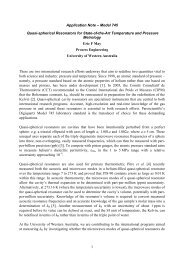
RDigiquartz® pressure transducer, while the <strong>Model</strong> 745 has an internalDigiquartz® pressure transducer.The <strong>Model</strong> <strong>735</strong>/745 display pressure measurement values and relatedinformation. They can be used as stand-alone instruments or as part of anRS-232 based data acquisition system. The units can be configured usingeither the front panel user interface or via the RS-232 serial port. Thefront panel user interface provides convenient access to the most oftenused configuration functions. Other configuration functions are accessedvia the RS-232 serial port.2.4 Front Panel Features<strong>Paroscientific</strong>, <strong>Inc</strong>.ON/OFFMENUENTERDigiquartz Laboratory Standard<strong>Model</strong> 745Figure 1. <strong>Model</strong> 745 front panelThe front panel contains the LCD display and the keypad. The LCDdisplay shows pressure measurement values on the first line, and yourchoice of several other display options on the second line. The keypadprovides access to the configuration menu. The configuration menuenables the user to quickly and conveniently set up the unit to suit theapplication.Please refer to paragraph 4.1 for more information about configurationmenu navigation. Please refer to Section 20 for more information aboutoptions available via the configuration menu.GETTING FAMILIAR 2-3
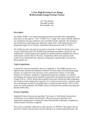
2.5 Rear Panel Features2.5.1 <strong>Model</strong> <strong>735</strong>Figure 2. <strong>Model</strong> <strong>735</strong> rear panelThe <strong>Model</strong> <strong>735</strong> rear panel contains the following features:• AC adapter jack• Power and I/O terminal block• RS-232 port• Battery compartment• Transducer terminal block• Chassis grounding lugPlease refer to paragraph 4.2 for detailed information about the <strong>Model</strong><strong>735</strong> rear panel features.GETTING FAMILIAR 2-4
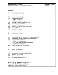
2.5.2 <strong>Model</strong> 745Figure 3. <strong>Model</strong> 745 rear panelThe <strong>Model</strong> 745 rear panel contains the following features:• Pressure port(s)• AC adapter jack• Power and I/O terminal block• RS-232 port• Battery compartment• Chassis grounding lugPlease refer to paragraph 4.2 for detailed information about the <strong>Model</strong>745 rear panel features.GETTING FAMILIAR 2-5
3 Quick StartThis section will help you to quickly set up the <strong>Model</strong> <strong>735</strong>/745 and begintaking pressure measurements.3.1 <strong>Model</strong> 745Step 1: Apply power to the <strong>Model</strong> 745Refer to paragraph 4.2.1 for detailed information.Step 2: Turn <strong>Model</strong> 745 onPress the ON/OFF key to turn on the <strong>Model</strong> 745. After a shortinitialization, the <strong>Model</strong> 745 will begin to display pressuremeasurement values.Your <strong>Model</strong> 745 should now be displaying correct pressuremeasurement values. If the displayed values are not correct, refer toSection 13 for troubleshooting tips.Refer to Section 4 for information about configuring your <strong>Model</strong> 745according to your application.3.2 <strong>Model</strong> <strong>735</strong>Step 1: Connect an external Digiquartz® pressuretransducer to the <strong>Model</strong> <strong>735</strong>• Refer to paragraph 18.1 for detailed information.Step 2: Apply power to the <strong>Model</strong> <strong>735</strong>• Refer to paragraph 4.2.1 for detailed information.Step 3: Turn <strong>Model</strong> <strong>735</strong> on• Press the ON/OFF key to turn on the <strong>Model</strong> <strong>735</strong>. After ashort initialization, the <strong>Model</strong> <strong>735</strong> will begin to displaypressure measurement values.Note: If the <strong>Model</strong> <strong>735</strong> has not yet been configured with thecalibration coefficients of the particular Digiquartz® pressuretransducer to which it is connected, incorrect pressuremeasurement values will be displayed and the overpressure alarmmay sound.QUICK START 3-1
Step 4: Establish communications between the <strong>Model</strong> <strong>735</strong>and a PC• Install Digiquartz® Interactive 2.0 on your PC. Digiquartz®Interactive 2.0 can be installed from the Digiquartz® CDLibrary that was included with your <strong>Model</strong> <strong>735</strong> ordownloaded at the <strong>Paroscientific</strong> web site atwww.paroscientific.com.• Connect the RS-232 port of your <strong>Model</strong> <strong>735</strong> to the RS-232port of your PC, and power up the instrument.• Run Digiquartz® Interactive 2.0.• Select the Digiquartz® Terminal option, and click Next.• You send commands to the unit by typing them into theCommand field. Responses to commands will be displayedin the Response window.If you are unable to establish communications, refer to theDQI online help information and Section 13 of this manual.Step 5: Configure the <strong>Model</strong> <strong>735</strong> with the Digiquartz®pressure transducer coefficients and parametersPlease refer to Section 5 for more information aboutconfiguration commands and their use.• Set the overpressure alarm setpointThe overpressure alarm setpoint (OP) is set to 0.0 psi at thefactory. OP is set in the current pressure units. Werecommend that the pressure units be set to psi (UN=1) priorto setting OP; refer to paragraphs 5.7.2.4 for details aboutsetting pressure units. OP should be set to the full-scalepressure indicated on the Digiquartz® transducer.The following example assumes a 45 psi transducer:Typical set command:Typical set response:*0100EW*0100OP=45*0001OP=45.00000QUICK START 3-2
• Set the transducer coefficient valuesThe following parameters must be set to the correspondingvalues on the Calibration Coefficients data sheet that wasdelivered with your Digiquartz® transducer:U0, Y1, Y2, Y3, C1, C2, C3, D1, D2, T1, T2, T3, T4, andT5.You must set all calibration parameters to the exact valueslisted on the Calibration Coefficients data sheet.CAUTION Setting calibration coefficients to incorrectvalues will result in incorrect pressure measurementvalues.The following example shows how to set the U0 coefficientto a typical value. Other coefficients are set in a similarmanner. Refer to paragraph 5.7.2.9 for more information.Typical set command:Typical set response:*0100EW*0100U0=5.860513*0001U0=5.860513• Set the transducer model numberMN should be set to the model number indicated on theDigiquartz® pressure transducer.The following example assumes a model 245A transducer.Typical set command:Typical set response:*0100EZ*0100MN=245A*0001MN= 245A• Set the transducer full-scale pressure valueSet PF to the full-scale pressure value indicated on theDigiquartz® pressure transducer. PF is set in the currentpressure units. We recommend that the pressure units be setto psi (UN=1) prior to setting PF. Refer to paragraph 5.7.2.4for more information about setting pressure units.QUICK START 3-3
CAUTION PF must be set to the full-scale pressure valueof the Digiquartz® transducer. Failure to do so will resultin improper formatting of pressure measurement values.The example below is for a 45 psi transducer.Typical set command:Typical set response:*0100EZ*0100PF=45*0001PF=45.00000• Set the transducer overpressure limit valuePL is typically set to 1.2 times the full-scale pressure value ofthe Digiquartz® transducer. Refer to the transducerSpecification Control Drawing for specific overpressurelimits. PL is always set and reported in psi, regardless of thepressure unit setting.The example shown below is for a 45 psi transducer (45 x 1.2= 54).Typical set command:Typical set response:*0100EZ*0100PL=54*0001PL=54.00000• Set the transducer type valueSet PO according to the Digiquartz® pressure transducertype (absolute, gauge, or differential). The table below showsthe integer values used with PO to identify the transducertype:QUICK START 3-4
PO value Transducer type0 Absolute1 Gauge2 DifferentialThe following example assumes an absolute transducer:Typical set command:Typical set response:*0100EZ*0100PO=0*0001PO=0• Set the transducer serial number valueSet SN to the serial number indicated on the Digiquartz®transducer.The following example assumes serial number 1234567:Typical set command:Typical set response:*0100EZ*0100SN=1234567*0001SN=1234567At this point, your <strong>Model</strong> <strong>735</strong> should be fully configured and shouldbe displaying correct pressure measurement values. If the displayedvalues are not correct, refer to Section 13 for troubleshooting tips.Refer to Section 4 for information about configuring your <strong>Model</strong> <strong>735</strong>according to your application.3.3 Applying PressureNow that you have your <strong>Model</strong> <strong>735</strong>/745 up and running, you are ready toconnect your pressure source to the pressure port. If you are using a<strong>Model</strong> 745, you will connect your pressure source to the pressure port(s)located on its rear panel. If you are using a <strong>Model</strong> <strong>735</strong>, your pressuresource will be connected directly to the pressure port of the externalDigiquartz® pressure transducer.ABSOLUTE UNITSUnits equipped with absolute pressure transducers have a single pressureport.QUICK START 3-5
GAUGE UNITSUnits equipped with gauge pressure transducers have two pressure ports.Pressure should only be applied to the positive pressure port. Thenegative pressure port must remain vented to atmospheric pressure.WARNING Consult the <strong>Model</strong> 745 or Digiquartz® pressure transducerSCD for proper pressure fitting tightening torque. Do not apply excessivetorque or permanent damage to the pressure fitting may result.WARNING When connecting pressure fittings, always use a secondwrench to stabilize the pressure fitting on the <strong>Model</strong> 745 or Digiquartz®pressure transducer, or permanent damage to the <strong>Model</strong> 745 orDigiquartz® pressure transducer may result.WARNING All Digiquartz® pressure transducer are designed to operateover a specific pressure range. Do not overpressure the <strong>Model</strong> 745 orDigiquartz® pressure transducer, or permanent damage may result.CAUTION Transducers that are intended to be used in liquid pressureapplications are oil-filled at <strong>Paroscientific</strong>. If your <strong>Model</strong> 745 orDigiquartz® pressure transducer is oil-filled, do not pull a vacuum orpressurize with gas, or gas bubbles may be introduced into the pressuretransducer, which will negatively affect its performance. Pressure linesconnected to oil-filled transducers should be filled with clean hydraulicfluid and bled to remove gas bubbles. Consult the <strong>Model</strong> 745 orDigiquartz® pressure transducer SCD to determine the oil used to fill thetransducer.CAUTION Pressure head effects result in zero offsets. These effects aremore pronounced when liquid-filled pressure lines are being used. Theseeffects can be minimized by keeping the transducer pressure port and thepressure source at the same elevation, or by using the tare or pressureadder functions to make an offset correction to compensate for thepressure head.QUICK START 3-6
CONFIGURATION MENU MODEConfiguration Menu Mode is accessed by pressing the MENU key whilein Pressure <strong>Display</strong> Mode. The most common functions of the <strong>Model</strong><strong>735</strong>/745 can be configured through the configuration menus. Lessfrequently used functions are accessed through the RS-232 port. SeeSection 5 for details. The configuration menus are organized in ahierarchical fashion, as shown in Section 20. The keypad is used to movethrough the menus, make selections, and change parameter values.When in Configuration Menu Mode, the first line displays either the menuname or a description of the parameter value being displayed. The secondline either displays the current menu option, or a parameter value.The <strong>Model</strong> <strong>735</strong>/745 automatically switches back to Pressure <strong>Display</strong>Mode if no user input is received for two minutes.WARNING Do not attempt to simultaneously access the <strong>Model</strong> <strong>735</strong>/745through the RS-232 port and the configuration menu. Doing so maycause serial commands or configuration menu selections to be ignored.4.1.3 KeypadThe functions of the keys are as follows:ON/OFF KEY• Turns the unit on and off.MENU KEY• When in Pressure <strong>Display</strong> Mode, pressing MENU puts the unit inConfiguration Menu Mode.• When in the configuration menus, pressing MENU takes youback to the previous menu level.• When in the MAIN MENU, pressing MENU takes you back toPressure <strong>Display</strong> Mode.• When in a parameter edit screen, pressing MENU aborts the editfunction, and takes you back to the previous menu level.DOWN ARROW KEY• When in the configuration menus, pressing DOWN ARROWscrolls the menu to the next menu option.USER INTERFACE 4-2
• When in a parameter entry screen, DOWN ARROW decrementsthe data value.UP ARROW KEY• When in a menu, pressing UP ARROW scrolls the menu to theprevious menu option.• When in a parameter entry screen, UP ARROW increments thedata value.ENTER KEY• When in the configuration menus, pressing ENTER selects thedisplayed menu item.• When in a parameter entry screen, ENTER accepts the displayedparameter value.4.1.4 Configuration Menu OptionsThe Configuration Menu allows you to configure the <strong>Model</strong> <strong>735</strong>/745according to your application. Refer to the Menu Quick Reference cardor the menu tree in Section 20.4.1.4.1 Tare MenuCURRENT VALUE<strong>Display</strong>s the current tare value. This is the value that is subtracted frompressure measurements when tare is on.TARETurns tare on. When tare is on, the current tare value is subtracted frompressure measurements. When Tare is selected, the pressure at that timebecomes the current tare value. If tare is already on when this option isselected, tare remains on, and the pressure at that time becomes the newcurrent tare value.When tare is on, a “T” is displayed to the left of the pressure value toindicate that it is a tared pressure value.TARE OFFTurns tare off. When tare is off, the actual measured pressure value isdisplayed.USER INTERFACE 4-3
4.1.4.2 Units MenuPRESSURE UNITSSelects the pressure unit. The following options are available:• psi• hPa• bar• kPa• MPa• inHg• mmHg• mH2O• User-defined pressure unitThe user-defined pressure unit can be selected via the configurationmenu, but must be configured via RS-232. Refer to Section 5 for details.TEMP. UNITSSelects the internal sensor temperature unit. The following options areavailable:• °C• °F4.1.4.3 <strong>Display</strong> MenuDECIMAL DIGITSSelects the number of significant digits used to display pressuremeasurement values. Fewer significant digits will be displayed if thepressure resolution and/or pressure unit will not provide the specifiednumber of significant digits. When the number of digits is set to 6, themaximum number of significant digits is always displayed.LINE 2 DISPLAYSelects the information to be displayed on the second line. The followingoptions are available:• Bar graph – gives a graphic representation of the current pressurevalue as a percentage of full-scale pressure.• Sensor Temp. – displays the Digiquartz® pressure transducerinternal temperature.USER INTERFACE 4-4
• Pressure Rate – displays the pressure rate of change in the currentpressure unit per second. Pressure rate is calculated as thedifference between adjacent pressure measurements divided bythe measurement time interval. Time interval accuracy is ±10milliseconds.• Stored Text – displays the text stored within the <strong>Model</strong> <strong>735</strong>/745.The text is defined via the RS-232 port using the UL parameter.Refer to paragraph 5.7.2.8 for more information.• External Text – displays the text sent via the RS-232 port usingthe DT command. The text is not stored within the <strong>Model</strong><strong>735</strong>/745, and will be lost if the unit is turned off.• No Line 2 – No information is displayed on the second line.The second line can also display an overpressure warning if the measuredpressure exceeds the limits of the Digiquartz® pressure transducer. Theoverpressure warning is not available when the external text displayoption has been selected. Depending on the second line display option,the overpressure warning is either “OVERPRESSURE!” or “OVPR”.4.1.4.4 Aux MenuSAMPLING TIMESelects the measurement sampling time. The range is .002 to 131.07seconds in .002-second increments.UNIT IDSelects the unit ID for networking applications. The range is 01 to 98.PASSWORDSelects the password required to change settings within the ConfigurationMenu. The password is a four-digit integer value. When the passwordvalue is 0000, the password function is disabled, and no password isrequired to change settings. When the password value is non-zero, thepassword will be requested each time a setting is to be changed. If theproper password is entered, the setting can be changed; if not, you will bereturned to the menu.Contact <strong>Paroscientific</strong> if you are unable to configure your <strong>Model</strong> <strong>735</strong>/745due to a lost password.USER INTERFACE 4-5
VERSION<strong>Display</strong>s the firmware versions. This information may be helpful fordiagnostic purposes.BAUD RATESelects the RS-232 baud rate. The following options are available:• 19200• 9600• 4800• 2400• 1200• 600• 300USER INTERFACE 4-6
4.2 Rear Panel4.2.1 Power OptionsThe <strong>Model</strong> <strong>735</strong>/745 provides three power options.AC ADAPTERA 120VAC or 230VAC AC adapter was supplied with the <strong>Model</strong><strong>735</strong>/745. It plugs into the power jack located in the lower left corner ofthe rear panel.BATTERIESThe <strong>Model</strong> <strong>735</strong>/745 can be powered by four AA alkaline batteries. A setof batteries was supplied with the unit. The battery compartment islocated on the rear panel. Open the battery compartment by inserting atool into the small opening at the top of the battery compartment coverand pressing downward while pulling the cover outward. Batteries mustbe installed per the diagram inside the battery compartment.The <strong>Model</strong> <strong>735</strong>/745 runs for more than 20 hours on a fresh set ofpremium AA alkaline batteries. The battery level is monitored, and“LOW BATTERY” is displayed on the second line when the batteries arenearly discharged. A few hours of operation remain at the time that the“LOW BATTERY” indication is first displayed.WARNING Use only AA alkaline batteries. Other types, includingrechargeable batteries, are not recommended.WARNING Do not allow batteries to remain in the <strong>Model</strong> <strong>735</strong>/745 foran extended period of time. Discharged batteries can become leaky overtime, and could cause significant damage to the unit. It is recommendedthat batteries be examined periodically for leakage, and that any suspectbatteries be removed. If the unit will not be used for an extended periodof time, it is recommended that the batteries be removed.WIRE INTERFACEThe DC Power – I/O terminal block provides a means of wiring DCpower to the <strong>Model</strong> <strong>735</strong>/745.USER INTERFACE 4-7
4.2.2 Terminal Block DescriptionsTerminal block(s) are provided for making wire connections to the <strong>Model</strong><strong>735</strong>/745. The terminal blocks can be unplugged from the unit to simplifywiring. Refer to the pinout diagrams on the rear panel label when makingconnections.DC POWER – I/O TERMINAL BLOCKThe DC Power – I/O terminal block provides the following connections:• DC power and power ground• <strong>Model</strong> 715 remote display signals• Overpressure outputRefer to paragraph 17.3 for detailed information regarding the DC Power– I/O terminal block. Refer to paragraph 5.7.2.5 for detailed informationregarding the overpressure output.TRANSDUCER INTERFACE TERMINAL BLOCK (MODEL <strong>735</strong>ONLY)The transducer interface terminal block provides the connections to theexternal Digiquartz® pressure transducer. Refer to paragraph 18.1 fordetailed information regarding the transducer interface terminal block4.3 Overpressure AlertThe overpressure alert is an audible alarm that works in conjunction withthe overpressure output. It sounds whenever the displayed pressureexceeds a user-selectable pressure setpoint. The setpoint is controlled viaRS-232 by the OP parameter. Refer to paragraph 5.7.2.5 for detailedinformation regarding the overpressure function and the OP parameter.USER INTERFACE 4-8
5 Remote Operation5.1 Local vs. RS-232 OperationThe <strong>Model</strong> <strong>735</strong>/745 can be operated either as a stand-alone unit, or as partof a computer-based data acquisition system via its RS-232communications port.Virtually all of the functionality of the <strong>Model</strong> <strong>735</strong>/745 is available via theRS-232 port. Some of the unit’s more specialized features can only beconfigured via the RS-232 port.No special configuration is required to access the <strong>Model</strong> <strong>735</strong>/745 via theRS-232 port. Simply connect its industry-standard RS-232 port to theRS-232 port of your host device, set your host device to the proper baudrate and serial protocol, and you are ready to communicate with the<strong>Model</strong> <strong>735</strong>/745.The <strong>Model</strong> <strong>735</strong>/745 RS-232 port is directly compatible with that of thePC. Any standard male to female 9-pin serial cable can be used to makethe necessary connections. A serial cable (<strong>Paroscientific</strong> PN 6409-003) issupplied with your <strong>Model</strong> <strong>735</strong>/745.WARNING Do not attempt to simultaneously access the <strong>Model</strong> <strong>735</strong>/745through the RS-232 port and the configuration menu. Doing so maycause serial commands or configuration menu selections to be ignored.5.2 Digiquartz® Software<strong>Paroscientific</strong> provides several software programs that simplify commonmeasurement and configuration tasks. These programs can be found onthe Digiquartz® CD Library, which is provided with the <strong>Model</strong> <strong>735</strong>/745.The latest versions of these and other software programs are alsoavailable at the <strong>Paroscientific</strong> web site, at www.paroscientific.com.5.2.1 Digiquartz® Interactive 2.0 (DQI 2.0)Digiquartz ® Interactive 2.0 is a Windows program that makes it easy tocommunicate with and configure DIGIQUARTZ® <strong>Intelligent</strong> devices.We encourage you to install DQI 2.0 and use it to verify proper deviceREMOTE OPERATION 5-1
operation, configure your device, take measurements, and experimentwith its functions.DQI 2.0 is separated into two main sections: Configuration andMonitoring, and Digiquartz® Terminal.The Configuration and Monitoring section provides a means of viewing,changing, storing, and retrieving the configuration parameters of yourinstrument. It also allows you to take measurements and display themnumerically and in a real-time graph. Measurement data may also belogged to a text file in a format that can be easily imported into popularPC programs such as Microsoft Excel® or Word®.The Digiquartz® Terminal section allows you to interactivelycommunicate with your instrument using text-based commands.Measurement data may be logged to a text file in a format that can beeasily imported into popular PC programs such as Microsoft Excel® orWord®.5.2.2 Digiquartz® Assistant (DQA)Digiquartz® Assistant is a Windows data logging program. With DQA,you can log time-stamped measurement data from up to 8 Digiquartz®intelligent devices. Measurement data can also be displayed in real timein an automatically scaled graph. Data is stored to a text file in a formatthat can easily be imported into popular PC programs such as MicrosoftWord or Excel. Refer to the help function in DQA for more information.5.2.3 Digiquartz® Terminal (DQT)Digiquartz® Terminal is a Windows terminal program that was developedspecifically for use with Digiquartz® intelligent devices. Like traditionalterminal programs, Digiquartz® Terminal lets you interactivelycommunicate with intelligent devices. In addition, Digiquartz® Terminalcan log time-stamped measurement data to a text file in a format that caneasily be imported into popular PC programs such as Microsoft Word orExcel. Refer to the help function in Digiquartz® Terminal for moreinformation.REMOTE OPERATION 5-2
5.3 Command and Response BasicsThe <strong>Model</strong> <strong>735</strong>/745 is remotely controlled by serial ASCII commandstrings. The following basic tasks can be accomplished by sending theappropriate command:• Take a measurement• Perform a control function, such as locking the baud rate• Set an operating parameter, such as integration time• Read the value of an operating parameterWhen setting virtually all parameter values, you must precede thecommand with an EW command. This prevents accidental alteration ofstored parameter values. Please refer to paragraphs 5.6 and 5.7.2.1 formore information about the EW command.Measurement commands typically generate a response that contains themeasurement data. Parameter-set commands typically generate aresponse that reports the updated parameter value. Parameter-readcommands report the current parameter value.When a command is received, any command that is in progress will beaborted. This enables you to send an RS-232 command to the <strong>Model</strong><strong>735</strong>/745 at any time, regardless of its current activity.5.4 Command and Response FormatIn general, RS-232 commands and responses are made up of thefollowing:START CHARACTER• The start character is an asterisk (ASCII 42).DESTINATION ID• The destination ID identifies the device that is to receive thecommand or response.• The destination ID is a two-digit integer between 00 and 99. ID00 is reserved for the serial host, usually a PC.SOURCE ID• The source ID identifies the device that is sending the commandor the response.REMOTE OPERATION 5-3
• The source ID is a two-digit integer between 00 and 98. ID 00 isreserved for the serial host, usually a PC.COMMAND OR RESPONSE DATA• A wide variety of commands and resulting response data areavailable. Refer to paragraph 5.7 for detailed information.TERMINATION CHARACTERS• The termination characters are carriage return (ASCII 13) andlinefeed (ASCII 10).COMMAND FORMATCommands are typically sent in the following format:*0100P3CrLfWhere: * = Start character Asterisk, ASCII 4201 = Destination ID ID of the <strong>Model</strong> <strong>735</strong>/745 that is toreceive the command.00 = Source ID ID of the device that is sending thecommand (Serial host is ID 00)P3 = CommandCr = Carriage return ASCII 13Lf = Linefeed character ASCII 10P3 is an example. Refer to paragraph5.7 for descriptions of the entirecommand set.RESPONSE FORMATResponses are typically received in the following format:*000114.4567CrLfREMOTE OPERATION 5-4
Where: * = Start character Asterisk, ASCII 4200 = Destination ID ID of the serial host that is to receivethe response.01 = Source ID ID of <strong>Model</strong> <strong>735</strong>/745 that isresponding14.4567 = Data Data sent in response to the priorcommand)Cr = Carriage return ASCII 13Lf = Linefeed character ASCII 10These examples are typical. Refer to paragraph 5.7 for specific detailsregarding each available command.5.5 Establishing RS-232 CommunicationsThe following are two methods of establishing and verifying RS-232communications between the <strong>Model</strong> <strong>735</strong>/745 and a PC.USING DIGIQUARTZ® INTERACTIVE 2.0 SOFTWAREThe easiest way to establish RS-232 communications is by usingDigiquartz® Interactive 2.0 (DQI 2.0) software.Step 1. Connect the <strong>Model</strong> <strong>735</strong>/745 to the PC: Connect the <strong>Model</strong><strong>735</strong>/745 RS-232 port to the PC RS-232 port using the serial cable(<strong>Paroscientific</strong> PN 6409-003) that was provided with the unit. Any otherstandard RS-232 serial cable intended for use with the PC can also beused.Step 2. Install DQI 2.0: Insert the Digiquartz® CD Library CD intoyour CDROM drive, and follow the installation instructions.Step 3. Run DQI 2.0: Power up the <strong>Model</strong> <strong>735</strong>/745, and run DQI 2.0.At the Startup screen, select the PC com port number that you are using,and click the Detect button. DQI 2.0 will search for the unit, andestablish communications with it automatically. Click the OK button toexit the Startup screen and enter DQI 2.0.At this point, DQI 2.0 should be able to communicate with the unit. Referto the DQI 2.0 help feature for more information about using DQI 2.0.REMOTE OPERATION 5-5
USING A TERMINAL PROGRAMA standard terminal program can also be used to establish RS-232communications with the <strong>Model</strong> <strong>735</strong>/745. Digiquartz® Terminal (DQT)software can be used for this purpose. DQT is provided on theDigiquartz® CD Library CD.Step 1. Connect the <strong>Model</strong> <strong>735</strong>/745 to the PC: Connect the <strong>Model</strong><strong>735</strong>/745 RS-232 port to the PC RS-232 port using the serial cable(<strong>Paroscientific</strong> PN 6409-003) that was provided with your unit. Anyother standard RS-232 serial cable intended for use with the PC can alsobe used.Step 2. Install DQT: Insert the Digiquartz® CD Library CD into yourCDROM drive, and follow the installation instructions. Any otherterminal program already installed on your PC can also usually be used.Step 3. Determine the current baud rate and ID settings of your<strong>Model</strong> <strong>735</strong>/745: Power up your unit, and press the MENU key to enterConfiguration Menu mode. From the MAIN MENU, scroll to Aux Menuand select it using the Enter key. Scroll the AUX MENU to Unit ID, andselect it using the Enter key. Note the unit ID. Press the MENU key toreturn to the AUX MENU. Scroll the AUX MENU to Baud Rate, andselect it using the Enter key. Note the baud rate; you may change thebaud rate using the UP ARROW and DOWN ARROW keys. Press theENTER key to return to Pressure <strong>Display</strong> mode.Step 4. Configure the terminal program: Set the com port to the PCcom port number that you are using. Set the baud rate to match the <strong>Model</strong><strong>735</strong>/745. Set the communications protocol to 8 data bits, no parity, and 1stop bit. If DQT is not being used, it is often necessary to configure theterminal program to append a line feed character to each carriage returncharacter.At this point, the terminal program should be able to communicate withthe unit. Refer to paragraph 5.7 for detailed command and responseinformation. Refer to the DQT reference feature for detailed informationabout using DQT.REMOTE OPERATION 5-6
5.6 Setting and Reading Parameter ValuesThe behavior of the <strong>Model</strong> <strong>735</strong>/745 is controlled by several operatingparameters. The values of these parameters are stored in non-volatilememory. Commands are provided to set and read the parameters values.Refer to paragraph 5.7.2 for detailed information about the variousparameters.SETTING PARAMETER VALUESEach parameter-set command must be preceded with the EW enable writecommand. The purpose of this is to reduce the chance of changing aparameter value by mistake. Parameter set commands will be ignoredunless they are preceded with an EW command. See paragraph 5.7.2.1for more information about the EW command.The following is an example of a parameter-set command preceded withthe EW (enable write) command. For this example, the UN (pressureunit) parameter will be set to a value of 1.Command:Response:*0100EW*0100UN=1CrLf*0001UN=1CrLfAll other writable parameters are set in the same way. Some parametersare read-only, and cannot be set.READING PARAMETER VALUESAll parameters can be read without preceding the command with an EW(enable write) command. The following is an example of a parameterreadcommand. For this example, the UN (pressure unit) parameter willbe read.Command:Response:*0100UNCrLf*0001UN=1CrLfCAUTION Repeatedly setting or reading parameter values maytemporarily prevent the display from being updated.REMOTE OPERATION 5-7
5.7 Command Reference5.7.1 Measurement CommandsThe following commands are used to initiate measurements, and tocontrol measurement integration time. For additional commandsassociated with Nano-Resolution, please refer to Section 6.5.7.1.1 Single Measurement CommandsThe following commands are used to initiate single measurements. Theyreturn the resulting measurement value as soon as it is available.P1Sample and send one pressure period measurement in units ofmicroseconds.Action: Measure pressure period, send pressure period value, andawait next command.Typical command: *0100P1Typical response: *000128.123456 (Value: 28.123456)Note: Repeatedly issuing the P1 command will temporarilyprevent the front panel display from being updated.P3Sample and send one pressure measurement in selectedengineering units.Action: Measure temperature period, measure pressure period,calculate temperature-compensated pressure, sendpressure value, and await next command.Typical command: *0100P3Typical response: *000114.71234 (Value: 14.71234)REMOTE OPERATION 5-8
Q1Sample and send one temperature period measurement in units ofmicroseconds.Action: Measure temperature period, send temperature periodvalue, and await next command.Typical command: *0100Q1Typical response: *00015.1234567 (Value: 5.1234567)Note: Repeatedly issuing the Q1 command will temporarilyprevent the front panel display from being updated.Q3Sample and send one temperature measurement in selectedengineering units.Action: Measure temperature period, calculate temperature, sendtemperature value, and await next command.Typical command: *0100Q3Typical response: *000122.345 (Value: 22.345)Note: Repeatedly issuing the Q3 command will temporarilyprevent the front panel display from being updated.5.7.1.2 Sample and Hold Measurement CommandsThe following commands are used to initiate and send single sample andhold measurements. Measurement values are held until the nextcommand is received. If the next command is a DB command, themeasurement value is sent; if it is any other command, the measurementvalue is lost. If a DB command is received before the measurementcommand is complete, the measurement value will be sent as soon as it isavailable.CAUTION Sample and hold commands will temporarily prevent thefront panel display from being updated until the DB command is receivedor the sample and hold command is cancelled by the next valid command.REMOTE OPERATION 5-9
P5P6Q5Q6DBSample and hold one pressure measurement in selectedengineering units.Action: Measure temperature period, measure pressure period,calculate temperature-compensated pressure, savepressure value, and await DB command.Typical command: *0100P5Typical response: No response until DB command is receivedSample and hold one pressure period measurement in units ofmicroseconds.Action: Measure pressure period, save pressure period value, andawait DB command.Typical command: *0100P6Typical response: No response until DB command is receivedSample and hold one temperature measurement in selectedengineering units.Action: Measure temperature period, calculate temperature, savetemperature value, and await DB command.Typical command: *0100Q5Typical response: No response until DB command is receivedSample and hold one temperature period measurement in units ofmicroseconds.Action: Measure temperature period, save temperature periodvalue, and await DB command.Typical command: *0100Q6Typical response: No response until DB command is receivedDump Buffer. Send a held measurement value.Action: If a measurement value is being held, send it, otherwisedo nothing.Typical command: *0100DBTypical response: *000114.12345 (Value: 14.12345)REMOTE OPERATION 5-10
5.7.1.3 Continuous Measurement CommandsThe following commands are used to initiate and control continuousmeasurements. Continuous measurement commands repeatedly takemeasurement samples and return measurement values until commanded tostop. Continuous measurements are cancelled by sending any validcommand.P2Continuously sample and send pressure period measurementvalues in units of microseconds.Action: Measure pressure period, send pressure period value, andrepeat until commanded to stop.Typical command: *0100P2Typical response: *000128.123456 (Value: 28.123456)*000128.123457 (Value: 28.123457)*000128.123456 … (Value: 28.123456)Note: The P2 command will temporarily prevent the front paneldisplay from being updated.P4Continuously sample and send pressure measurement values inselected engineering units.Action: Measure temperature period, measure pressure period,calculate temperature-compensated pressure, sendpressure value, and repeat until commanded to stop.Typical command: *0100P4Typical response: *000114.71234 (Value: 14.71234)*000114.71235 (Value: 14.71235)*000114.71234 … (Value: 14.71234)REMOTE OPERATION 5-11
P7High-speed continuous pressure measurement in selectedengineering units.Action: Continuously sample and send pressure measurementvalues, using temperature measurement interval specifiedby the current value of PS. P7 automatically performsthe following sequence:1. Initially measure temperature period.2. Measure pressure period.3. Calculate temperature-compensated pressure usinglast temperature period measurement.4. Send pressure value.5. Do steps 2-4 the number of times specified by PS,then measure temperature period.6. Repeat steps 2-5 until commanded to stop.Typical command: *0100P7Typical response: *000114.71234 (Value: 14.71234)*000114.71235 (Value: 14.71235)*000114.71234 … (Value: 14.71234)Note:P7 allows you to maximize the pressure sampling rate bytaking temperature measurements at the interval specifiedby the PS command. Each subsequent pressure value istemperature-compensated using the currently storedtemperature value. You can take a single initialtemperature measurement, or you can take periodictemperature measurements at the interval you select withthe PS command. Please refer to the PS command formore information.REMOTE OPERATION 5-12
PSSet or read the temperature measurement interval used by the P7command.Action: Controls how often temperature measurements are takenduring a P7 pressure measurement sequence.If PS=0, an initial temperature measurement is taken, andall subsequent pressure measurements are compensatedusing that value.If PS=1, a temperature measurement is taken before eachpressure measurement (same as P4).If PS=n and n>1, an initial temperature measurement istaken, and subsequent temperature measurements aretaken after every n pressure measurements.Range: 1 to 65535Typical command: *0100EW*0100PS=4Typical response: *0001PS=4Note: When setting virtually all parameter values, you mustprecede the command with an EW (Enable Write)command. Please refer to paragraph 5.7.2.1 for moreinformation.Q2Continuously sample and send temperature period measurementvalues in units of microseconds.Action: Measure temperature period, send temperature periodvalue, and repeat until commanded to stop.Typical command: *0100Q2Typical response: *00015.1234567 (Value: 5.1234567)*00015.1234568 (Value: 5.1234568)*00015.1234567 … (Value: 5.1234567)Note: The Q2 command will temporarily prevent the front paneldisplay from being updated.REMOTE OPERATION 5-13
Q4Continuously sample and send temperature measurement valuesin selected engineering units.Action: Measure temperature period, calculate temperature, sendtemperature value, and repeat until commanded to stop.Typical command: *0100Q4Typical response: *000122.345 (Value: 22.345)*000122.346 (Value: 22.346)*000122.345 … (Value: 22.345)Note: The Q4 command will temporarily prevent the front paneldisplay from being updated.5.7.2 Configuration Commands5.7.2.1 Enable Write CommandWhen setting virtually all parameter values, you must precede theparameter set command with an EW (enable write) command. Parameterset commands will be ignored unless they are preceded with an EWcommand.EWEnables the next parameter set command to write a new valueinto non-volatile memory. You can issue EW as a separatecommand by terminating it with a carriage return/line feed, oryou can string the EW and parameter set commands together, asshown below.Typical syntax:Alternate syntax:*0100EW *0100TR=800*0100EW*0100TR=8005.7.2.2 Measurement Integration Time CommandsThe <strong>Model</strong> <strong>735</strong>/745 supports two measurement integration modes: timebasedand period-based. Time-based integration samples the transducerpressure and temperature signals for a specified time, and period-basedintegration samples the signals for a specified number of periods of theREMOTE OPERATION 5-14
TIME-BASED INTEGRATION TIME COMMANDSPITISet or read the time-based pressure measurement integration timeUnits: MillisecondsRange: 1 to 65535. Resolution is 10 milliseconds. Values arerounded to the next multiple of 10. Example: A valueof 11 results in a pressure integration time of 10milliseconds, and a value of 15 results in a pressureintegration time of 20 milliseconds.Default: 670Typical set command: *0100EW*0100PI=1000Typical set response: *0001PI=1000Typical read command: *0100PITypical read response: *0001PI=1000Note: Whenever the value of PI is changed, TI is automaticallyupdated with the same value.Set or read time-based temperature measurement integration timeUnits: MillisecondsRange: 1 to 65535. Resolution is 10 milliseconds. Values arerounded to the next multiple of 10. Example: A valueof 11 results in a temperature integration time of 10milliseconds, and a value of 15 results in a temperatureintegration time of 20 milliseconds.Default: 670Typical set command: *0100EW*0100TI=1000Typical set response: *0001TI=1000Typical read command: *0100TITypical read response: *0001TI=1000Note:Whenever the value of PI is changed, TI is automaticallyupdated with the same value. Changing TI has no effecton PI. TI should be set to the value as PI for optimumperformance in most applications.REMOTE OPERATION 5-16
5.7.2.3 Data Output Mode CommandThe following command controls whether pressure data is continuouslyoutput, and whether display data are produced.MDSet or read the data output mode.Action: MD configures the <strong>Model</strong> <strong>735</strong>/745 for continuous serialpressure measurement output and/or display data outputwhenever power is applied.MDvalue<strong>Display</strong> dataoutputContinuous serialpressure data output0 OFF OFF1 ON OFF2 OFF ON3 ON ONOnce MD is set, the specified data output mode willremain in effect until MD is set to a different value, eventhrough a power cycle. Therefore, the <strong>Model</strong> <strong>735</strong>/745will perform the specified data output function wheneverpower is applied.Range: 0-3Default: 1Typical set command:Typical set response:Typical read command:Typical read response:*0100EW*0100MD=1*0001MD=1*0100MD*0001MD=1CAUTION If MD is set to 0 or 2, the front panel display will nolonger be updated. For most applications, MD should only be setto 1 or 3. MD settings of 0 and 2 are supported only forcompatibility with other Digiquartz® <strong>Intelligent</strong> Instruments.REMOTE OPERATION 5-18
Note:When MD is set to a non-zero value, the specified dataoutput mode will be preempted under the followingconditions:• Continuous serial pressure data output is suspended when ameasurement command is received. Continuous dataoutput resumes when the measurement command iscomplete.• <strong>Display</strong> data output is suspended when a periodmeasurement command (P1, P2, P6, Q1, Q2, Q6) isreceived. <strong>Display</strong> data output resumes when the periodmeasurement command is complete.• Continuous pressure data output is suspended when acontinuous measurement command (P2, P4, P7, Q2, Q4) isreceived, and resumes when the continuous measurementcommand is cancelled.REMOTE OPERATION 5-19
5.7.2.4 Engineering Units CommandsEngineering units commands are used to specify the engineering units tobe used when calculating pressure or temperature values, and to configurethe user-defined pressure unit.UNSet or read the pressure engineering units.Action: Sets or queries the conversion factor by which allcalculated pressure values are multiplied before beingoutput. Setting UN to a non-zero value selects one ofeight standard pressure units; 0 selects a user-defined unitwhose conversion factor is specified by the UFcommand. UN also sets the units of the pressure datadisplayed by an optional <strong>Model</strong> 715 display.Range: 0 to 8UNvaluePressureunitspsi multipliedby…0 User-defined pressure unit Value of UF1 psi 1.00000002 hPa (mbar) 68.947573 bar 0.068947574 kPa 6.8947575 MPa 0.006894766 in Hg 2.0360217 mm Hg (Torr) 51.714938 m H 2 O 0.7030696Default: 1Typical set command: *0100EW*0100UN=2Typical set response: *0001UN=2Typical read command: *0100UNTypical read response: *0001UN=2REMOTE OPERATION 5-20
UFTUSet or read the user-defined pressure engineering units conversionfactor.Action: When UN=0, calculated pressure values (psi) aremultiplied by the value of UF before being output, thusscaling the pressure values in the desired user-definedpressure units.Range: -9999999 to 9999999Default: 1.0000000Typical set command: *0100EW*0100UF=2Typical set response: *0001UF=2Typical read command: *0100UFTypical read response: *0001UF=2.000000Set or read the temperature engineering units.Action: Specifies the temperature units for Q3, Q4, Q5, anddisplayed temperature data.Range: 0 = °C1 = °FDefault: 0Typical set command: *0100EW*0100TU=1Typical set response: *0001TU=1Typical read command: *0100TUTypical read response: *0001TU=1Note: Temperature is always calculated in °C, but it is convertedto °F if TU=1.5.7.2.5 Tare and Overpressure CommandsTaring is the process of subtracting a specified value from pressuremeasurements. You may use a measured pressure as the tare value, oryou may specify any desired value. Taring can be enabled, disabled, andlocked out through the use of serial commands. RS-232 pressuremeasurement data can be formatted to include an indication when taringis in effect. Refer to the ZI command for more information.REMOTE OPERATION 5-21
The overpressure command can be used to specify the overpressure alarmsetpoint. When the overpressure setpoint is exceeded, the overpressureI/O line changes from logic low (0 VDC) to logic high (5.0 VDC)ZSSet or read the tare state parameter value.Action: The three states of ZS are as follows:ZS=0 Taring function is off.ZS=1 Taring has been requested, but is not yet ineffect.ZS=2 Taring is in effectZS is set to 0 on power-up. If ZL=0 (taring is not lockedout), taring can be requested by setting the ZS to 1. Atthe first pressure measurement following a tare request,the following sequence occurs:• The pressure value is stored in the ZV parameter.• The value of ZS is set to 2 to indicate that taring is ineffect.• The value of ZV is subtracted from all subsequentpressure values until taring is turned off.If taring is already in effect when a ZS=1 command isissued, the sequence described above occurs, and taringcontinues using a new value of ZV.Taring can be turned off by issuing a ZS=0 command.Range: 0 to 2Default: 0Typical set command: *0100EW*0100ZS=1Typical set response: *0001ZS=1Typical read command: *0100ZSTypical read response: *0001ZS=1REMOTE OPERATION 5-22
ZVSet or read the tare value.Action: Sets or queries the value that is subtracted from pressuremeasurements when taring is activated. ZV can be set toany desired value when taring is in effect (ZS=2). Note,however, that if taring is subsequently requested, a newvalue will overwrite the ZV value you have set.The value of ZV is set to 0 on power-up.Range: -9999999 to 9999999Default: 0Typical set command: *0100EW*0100ZV=14.7123Typical set response: *0001ZV=14.7123Typical read command: *0100ZVTypical read response: *0001ZV=14.7123ZLSet or read the tare lockout parameter value.Action: When ZL=0, ZS can be set to enable and disable taring.When ZL=1, taring is locked, and the value of ZS cannotbe modified via serial commands or the Tare Input I/Oline. However, if ZS=1 and a ZL=1 command is issued,taring will be in effect when the next pressuremeasurement is taken, but you cannot turn taring off untilZL is set to 0.The value of ZL is set to 0 on power-up.Range: 0 or 1Default: 0Typical set command: *0100EW*0100ZL=1Typical set response: *0001ZL=1Typical read command: *0100ZLTypical read response: *0001ZV=1REMOTE OPERATION 5-23
OPSet or read the overpressure alarm setpoint value.Action: When a pressure measurement value is less than the valueof OP, the overpressure I/O line is at logic low (0 VDC)and the overpressure alert is silent; if it is greater or equalto the value of OP, the overpressure I/O line is set tologic high (5.0 VDC), and the overpressure alert sounds.OP is set in the current pressure units, and is scaledaccordingly if the engineering units are changed.Range: -9999999 to 9999999Default: Maximum rated unit pressureTypical set command: *0100EW*0100OP=15Typical set response: *0001OP=15.00000Typical read command: *0100OPTypical read response: *0001OP=15.000005.7.2.6 Measurement Data Formatting CommandsThese commands are used to alter the format of serial measurement data.The following data formatting functions are available:• Append engineering units to pressure and temperaturemeasurement data• Append a taring indication to tared pressure measurement data• Add underscores to separate the measurement data from the restof the serial output data string to improve readability• Add trailing zeroes to the measurement data to create a fixedlengthdata string to simplify parsingFormatting commands can be used separately or in any combination.REMOTE OPERATION 5-24
USSet or read the engineering units suffix parameter value.Action: When US=1, an engineering units label is appended topressure and temperature measurement data. WhenUS=0, no engineering units label is appended.Examples: *000114.71234 (Pressure measurement, US=0)*000114.71234psia (Pressure measurement, US=1)*000121.123 (Temp measurement, US=0)*000121.123C (Temp measurement, US=1)When US=1, a pressure unit label is appended to pressuremeasurement values, according to the value of UN:UN value Label0 Defined by UM1 psia, psig, or psid2 hPa3 bar4 kPa5 MPa6 inHg7 mmHg8 mH2OWhen US=1, a temperature unit label is appended to temperaturemeasurement values, according to the value of TU:TU value Label0 C1 FRange: 0 or 1Default: 0Typical set command: *0100EW*0100US=1Typical set response: *0001US =1Typical read command: *0100USTypical read response: *0001US =1REMOTE OPERATION 5-25
SUSet or read the underscore separator parameter value.Action: When SU=1, an underscore separates the measurementdata from the address header and the optional engineeringunits suffix. When SU=0, no underscore separatorsappear.Examples: *000114.71234 (SU=0)*0001_14.71234 (SU=1)*0001_14.71234_psia (SU=1, US=1)Range: 0 or 1Default: 0Typical set command: *0100EW*0100SU=1Typical set response: *0001SU=1Typical read command: *0100SUTypical read response: *0001SU=1ZISet or read the taring indication parameter value.Action: When ZI=1, a “T” is appended to pressure measurementvalues when taring is in effect. When ZI=0, no taringindication appears, whether taring is in effect or not.Examples: *000114.71234*000114.71234T*0001_14.71234T*000114.71234Tpsia*0001_14.71234T_psia(ZI=0)(ZI=1)(ZI=1, SU=1)(ZI=1, US=1)(ZI=1, US=1, SU=1)Range: 0 or 1Default: 0Typical set command: *0100EW*0100ZI=1Typical set response: *0001ZI=1Typical read command: *0100ZITypical read response: *0001ZI=1REMOTE OPERATION 5-26
DLSet or read the fixed field data format parameter.Action: When DL=1, measurement data is formatted in a fixedfield format. When DL=0, measurement data is given inthe standard format.The fixed field format is specified as follows:*AAAASDDDDDDDDDD, where* = the asterisk characterA = destination and source address charactersS = sign of pressure data, either + or –D = numeric representation of pressure data, either digitsor a decimal pointExamples: *000114.71234 (Pressure, DO=0)*0001+14.7123400 (Pressure, DO=1)*000121. 123 (Temperature, DO=0)*0001+21.1230000 (Temperature, DO=1)Range: 0 or 1Default: 0Typical set command: *0100EW*0100DL=1Typical set response: *0001DL=1Typical read command: *0100DLTypical read response: *0001DL=1Note: The format specification and examples shown aboveassume that the other formatting commands are disabled.If other formatting commands are used in combinationwith DL, a fixed field format will still result, but theformat specification will vary slightly from the onedescribed above.REMOTE OPERATION 5-27
UMSet or read the user-defined engineering units label parameter.Action: When UN=0 and US=1, the text value of UM isappended to pressure measurements.Examples: *000114.71234*000114.71234user(UN=0, US=0)(UN=0, US=1, UM=user)Range: Any text up to four characters, consisting of ASCII 32to ASCII 127.Default: userTypical set command: *0100EW*0100UM=testTypical set response: *0001UM=testTypical read command: *0100UMTypical read response: *0001UM=test5.7.2.7 Unit Identification CommandsThe Unit Identification commands read various device-specificparameters. These parameters are factory-set, and cannot be modified.SNRead the serial number.Action: The SN parameter contains the device serial number. SNis a read-only command.Typical read command: *0100SNTypical read response: *0001SN=12345VRRead the firmware version number.Action: The VR parameter contains the device firmware versionnumber. VR is a read-only command.Typical read command: *0100VRTypical read response: *0001VR=D1.02REMOTE OPERATION 5-28
MNRead the model number.Action: The MN parameter contains the device model number asa text string. The value of MN always contains 16characters. If the model number is less than 16characters, the string will be padded with trailing spacesto a length of 16 characters. MN is a read-onlycommand.Typical read command: *0100MNTypical read response: *0001MN=745-15APFRead the full-scale pressure value.Action: The PF parameter contains the full-scale pressure valuein the current pressure units. If the units are changed, thevalue of PF is scaled accordingly. PF is a read-onlycommand.Typical read command: *0100PFTypical read response: *0001PF=30.00000PORead the pressure transducer type.Action: The PO parameter contains the pressure transducer type.PO is a read-only command.PO value Transducer type0 Absolute1 Gauge2 DifferentialTypical read command: *0100POTypical read response: *0001PO=0REMOTE OPERATION 5-29
5.7.2.8 <strong>Display</strong> Data Configuration CommandsThe <strong>Display</strong> Configuration commands allow you to alter the informationshown on the display. They also control the display of the optional <strong>Model</strong>715 Remote <strong>Display</strong>.DPDTSet or read the maximum number of decimal places in thedisplayed pressure value.Action: DP sets the maximum number of decimal places in thedisplayed pressure value. Fewer decimal places will bedisplayed if the pressure resolution and/or pressure unitwill not provide the specified number of decimal places.When DP is set to 6, the maximum number of decimalplaces is always displayed, according to current pressureresolution.Range: 0 to 6Default: 6Typical set command: *0100EW*0100DP=6Typical set response: *0001DP=6Typical read command: *0100DPTypical read response: *0001DP=6Set the text to be displayed on the second line when the ExternalText display option is selected from the Configuration Menu.Use DT when the <strong>Model</strong> <strong>735</strong>/745 is to be controlled by an RS-232 serial host, and the text must be updated frequently.Action: DT allows a serial host (such as a PC) to send text to bedisplayed on the bottom line. The text sent using DT isnot stored by the <strong>Model</strong> <strong>735</strong>/745; it is simply transferredto its display. DT cannot be queried, and it is notnecessary to precede DT with an EW command. Thetext is lost when the <strong>Model</strong> <strong>735</strong>/745 is powered off.Range: 16 characters maximum. Any characters in the rangeof ASCII 32 to ASICC 127 are legal.Typical set command: *0100DT=This is my textTypical set response: *0001DT=This is my textREMOTE OPERATION 5-30
PLRead the overpressure indication setpoint. This setpoint is usedto determine the pressure at which the overpressure indication isdisplayed. PL is a factory-set, read-only command.Action: When the <strong>Model</strong> <strong>735</strong>/745 measures a pressure greaterthan the value of PL, an overpressure indication isdisplayed.Typical read command: *0100PLTypical read response: *0001PL=120.0000Note: PL is typically factory-set to the overpressure limit asspecified in the Specification Control Drawing for theDigiquartz® transducer.ULSet or read the text to be displayed on the second line when theStored Text display option is selected from the ConfigurationMenu.Action: UL defines the text to be displayed on the bottom line.The value of UL is stored in non-volatile memory, andwill therefore be retained even if power is lost.Range: 11 characters maximum. Any characters in the rangeof ASCII 32 to ASCII 127 are legal.Default: 11 space charactersTypical set command: *0100EW*0100UL=My labelTypical set response: *0001UL=My labelTypical read command: *0100ULTypical read response: *0001UL=My labelCAUTION Do not use UL if it is necessary to update thedisplayed text often; use the External Text display option and theDT command instead. The nonvolatile memory used to store thetext data can be written approximately 100,000 times; excessiveuse of UL will eventually result in the inability to change itsvalue.REMOTE OPERATION 5-31
5.7.2.9 Calibration CommandsThe calibration commands set and read several parameters that directlyaffect the measurement accuracy of the device. Refer to Section 10 formore information regarding the use of the calibration parameters.CAUTION Calibration values should be modified only when absolutelynecessary, and then with extreme caution. Calibration adjustments shouldonly be performed by a qualified metrology lab.PA and PM are used in the following formula to calculate final outputpressure:P adjusted = PM * (P + PA)Where: P = Pressure calculated using originalcalibration coefficients, in thecurrent pressure unitsPM =the current value of the PMparameterPA = the current value of the PAparameterPASet or read the pressure adder parameter.Action: The pressure adder parameter is used to make zeroadjustments to the calibration. PA can also be used tooffset absolute pressure measurements by atmosphericpressure to obtain gauge pressure.Range: -9999999 to 9999999Default: 0.0Typical set command: *0100EW*0100PA=.0000123Typical set response: *0001PA=.0000123Typical read command: *0100PATypical read response: *0001PA=.0000123REMOTE OPERATION 5-32
Note: The value of PA is entered in the current pressure units,but is converted to psi prior to being stored. When PA isqueried, it returns the value scaled to the current pressureunits.PMSet or read the pressure multiplier parameter.Action: The pressure multiplier parameter is used to make spanadjustments to the calibration.Range: -9999999 to 9999999Default: 1Typical set command: *0100EW*0100PM=1.000123Typical set response: *0001PM=1.000123Typical read command: *0100PMTypical read response: *0001PM=1.000123Note: The value of PM is dimensionless, and is therefore notscaled if the units are changed.TCRead the crystal timebase correction factor.Action: TC is used to normalize the nominal 14.7456 MHzreference crystal frequency to 10 MHz to compensate forthe natural variation in reference crystal resonantfrequency. TC is a read-only command.Typical read command: *0100TCTypical read response: *0001TC=.6666667REMOTE OPERATION 5-33
C1C2C3D1D2T1T2T3T4T5U0Y1Y2Y3Set or read the calibration coefficients. See paragraph 7.8 andSection 10 for more information about calibration and calibrationcoefficients.Default: Device-specificTypical set command: *0100EW*0100C1=228.1234Typical set response: *0001C1=228.1234Typical read command: *0100C1Typical read response: *0001C1=228.12345.7.2.10 Diagnostic CommandsIn the unlikely event of a hardware failure, the diagnostic commands canassist in the troubleshooting process.CSRead the number of unused bytes on the stack since power-up.Action: CS is read-only; it cannot be set. It can be used todetermine whether a stack overflow may have occurred.Typical read command: *0100CSTypical read response: *0001CS=8REMOTE OPERATION 5-34
CXCheck timebase crystal frequency.Action: Puts the timebase frequency divided by 480 on the TareOutput I/O line. The timebase signal is removed from theTare Output I/O line when the next valid command isreceived. CX cannot be queried. The CX set commanddoes not produce a response.Typical set command: *0100CXTypical set response: No response5.7.2.11 Global CommandsUnder certain circumstances, it may be desirable to send a singlecommand to multiple units on a serial loop network. The ID 99 has beenreserved for such global addressing. When a <strong>Model</strong> <strong>735</strong>/745 receives alegal command addressed to ID 99, it reacts to that command regardlessof its assigned ID value.When the <strong>Model</strong> <strong>735</strong>/745 receives a global command via RS-232, itretransmits the global command before acting on it. This ensures that allunits on a serial loop will receive the global command. Eventually, theglobal command is retransmitted by the last unit in the serial loop and isreceived by the serial host. The serial host must be able to disregard theretransmitted command.Global addressing is often used with sample and hold measurementcommands to synchronize measurements from multiple devices. Thesample and hold measurement commands are:P5 and P6Q5 and Q6REMOTE OPERATION 5-35
All sampling commands and certain other commands may be eitherindividually or globally addressed:P1 through P7Q1 through Q6DBVREWThe remaining commands should not be sent as global commands5.8 High Speed SamplingUse one or more of the following techniques to increase the RS-232sampling rate.• Reduce integration time. Refer to PI, TI, PR, and TR commandsin paragraph 5.7.2.2.• Use PR and TR rather than PI and TI to control integration time.PR and TR have approximately 1ms resolution, compared to10ms of PI and TI. See paragraph 5.7.2.2 for details• Use a continuous pressure measurement command, such as P4 orP7. See paragraph 5.7.1.3 for details.• Turn off display data output. Refer to the MD command inparagraph 5.7.2.3.• <strong>Inc</strong>rease the baud rate. Refer to paragraph 4.1.4.4.• Use the continuous pressure period command (P2), and postprocessdata to convert to pressure. Refer to paragraph 7.8 fordetailed information about converting period measurements intopressure values.5.9 NetworkingThe <strong>Model</strong> <strong>735</strong>/745 supports RS-232 serial loop networking. Networkingallows you to communicate with up to 98 Digiquartz® <strong>Intelligent</strong> devicesfrom a single RS-232 serial host.REMOTE OPERATION 5-36
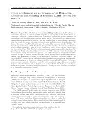
5.9.1 Networking BasicsWhen setting up a network, the following points must be observed.• If your network includes older <strong>Intelligent</strong> transmitters that supportRS-232 only, set the older devices to PT = N to assurecompatibility with the <strong>Model</strong> <strong>735</strong>/745.• Verify proper operation of each <strong>Intelligent</strong> device beforeinstalling it in a network.• Set all <strong>Intelligent</strong> devices to the same baud rate before installingthem in a network.• Each <strong>Intelligent</strong> device on the network needs to be set to a uniqueID.5.9.2 RS-232 Loop NetworkingRefer to Figure 4. In an RS-232 serial loop network, the transmit outputof the RS-232 host is connected to the receive input of the first device inthe loop. The transmit output of the first device is connected to thereceive input of the next device. The remaining devices are connectedsimilarly, with their receive input connected to the transmit output of theprevious device, and their transmit output connected to the receive inputof the next device. The transmit output of the last device is connected tothe receive input of the RS-232 host.The host sends commands to the first device in the loop. If a command isaddressed to that device, the command is carried out; if not, the commandis resent to the next device. Globally addressed commands are carried outby each device, and are also resent to the next device. When a deviceresponds to a command, the response is addressed to the host, and istherefore resent by each device that receives it until it eventually makes itway to the serial host.REMOTE OPERATION 5-37
Figure 4. Serial loop network block diagramKeep these points in mind when designing an RS-232 serial loop network:• As previously described, each device resends any command orresponse that is addressed to another device. Since each deviceconsiders resending to be a higher priority than sending its ownresponse, it is possible that a device can spend all its timeresending, and never have an opportunity to send its ownresponse. This occurs only when one or more upstream devicesare continuously transmitting. To prevent this situation:• Operate your network at 9,600 baud or above• Avoid continuous transmission (P2, P4, P7, Q2, and Q4commands) at extremely low integration times• It is not possible to precisely synchronize measurements from twoor more devices by sending a global measurement command.This is a result of the delay that occurs as the measurementcommand propagates through the serial loop.• When a global command is sent, it propagates through the serialloop, eventually making its way back to the host. Therefore, thedata received by the host in response to a global commandincludes the command itself, followed by the individual responsesfrom all devices on the network.REMOTE OPERATION 5-38
5.10 <strong>Display</strong>ing Data Remotely with <strong>Model</strong> 715<strong>Display</strong>The <strong>Model</strong> 715 <strong>Display</strong> can be used to replicate the <strong>Model</strong> <strong>735</strong>/745display data at a distance of up to 4000 feet.The <strong>Model</strong> 715 display is identical to that of the <strong>Model</strong> <strong>735</strong>/745, with thefollowing exceptions:• Pressure rate of change data cannot be displayed on the <strong>Model</strong>715. If the <strong>Model</strong> <strong>735</strong>/745 is set up to display pressure rate ofchange, the second line of the <strong>Model</strong> 715 will not be updated.• When the <strong>Model</strong> <strong>735</strong>/745 configuration menu is accessed, the<strong>Model</strong> 715 will not display the configuration menu, but willcontinue to display pressure values.Using the <strong>Model</strong> 715 with the <strong>Model</strong> <strong>735</strong>/745 is simple and easy. Simplyconnect the units as shown in paragraph 0. Turn on the <strong>Model</strong> <strong>735</strong>/745;then turn on the <strong>Model</strong> 715. The <strong>Model</strong> 715 will automaticallysynchronize its baud rate to that of the <strong>Model</strong> <strong>735</strong>/745; this may take asmuch as a few minutes. When the <strong>Model</strong> 715 has synchronized, it willbegin to replicate the <strong>Model</strong> <strong>735</strong>/745 display.REMOTE OPERATION 5-39
6 Nano-Resolution Features &Functions6.1 IntroductionWith firmware revision D1.06 or later, it is now possible to achieveparts-per-billion resolution (nano-resolution). This feature can beenabled by software command. When disabled, the sensor isbackward compatible and works in the standard mode with typicalparts-per-million resolution. Nano-resolution is achieved by subsamplingthe pressure at a much higher rate (typically 8 kHz) andapplying digital signal processing techniques. Because of the muchhigher processing requirements, more input power is required. Ingeneral, the nano-resolution feature is only useful if the pressure isstable enough over the effective sampling period and if the dataacquisition system can handle additional digits. The practicalbandwidth of interest is in the infrasound and deep infrasound (10 to0.001 Hz).Two methods for nano-resolution are available. The first methodprocesses the sub-samples in a finite time interval (analogous to theintegration time of the standard mode). The digital process is an FIRfilter (finite impulse response). The resolution can be directlycompared to the resolution of the standard mode at the samesampling rate (synchronized). The algorithm performs a least-squares(regression) fit over the sub-samples to estimate the best value ofpressure. While the resolution is statistically two orders of magnitudebetter than the standard mode, it does not suppress aliasing errors.A second and usually preferred method is the IIR filter (infiniteimpulse response). It consists of a 5-stage digital low-pass filteracting on the sub-samples. It filters all frequencies with a roll-off of -100 dB/decade above a user selectable cutoff frequency. It is aneffective anti-aliasing filter. The inherent resolution depends on thecutoff frequency and not on the sampling period. Typically, thesampling rate is set at twice the cutoff frequency (Nyquist limit).NANO-RESOLUTION FEATURES & FUNCTIONS 6-1
6.2 Enabling Nano-ResolutionNano-resolution can be enabled and disabled by the XM serialcommand.XMSet or read the resolution mode.Range: 0 = Standard Resolution Mode (backward compatible)1 = Nano-resolution, IIR Filter Mode2 = Nano-resolution, FIR Filter ModeDefault: 0Typical set command: *0100EW*0100XM=1Typical set response: *0001XM=1Typical read command: *0100XMTypical read response: *0001XM=16.3 Configuring IIR Filter ModeSETTING RESOLUTIONResolution is a function of the cutoff frequency when operating inIIR mode. The cutoff frequency is user-selectable and is set by theIA command.IASet or read the cutoff frequency setting.Range: 0 - 16Default: 11Typical set command:Typical set response:Typical read command:Typical read response:*0100EW*0100IA=11*0001IA=11*0100IA*0001IA=11See Table 1 for a list of ranges for IA values, cutofffrequencies, measurement resolution, and the number ofdigits reported via RS-232.NANO-RESOLUTION FEATURES & FUNCTIONS 6-2
Table 1: IIR Filter Mode Typical Resolution RangesIA(1) CutoffFrequency(2) EffectiveTime Interval(3) PeriodResolution(4) MeasurandResolution(4) Measurand(Hz) (ms) (dB) (dB) (ppm/ppb)Resolution0 1400 0.1 -82 -62 790 ppm 61 700 1 -94 -74 200 ppm 72 350 2 -105 -85 56 ppm 73 175 3 -117 -97 14 ppm 84 88 6 -127 -107 4.5 ppm 85 44 11 -140 -120 1.0 ppm 86 22 22 -149 -129 0.35 ppm 97 11 44 -157 -137 0.14 ppm 98 5.5 89 -167 -147 45 ppb 109 2.8 178 -177 -157 14 ppb 1010 1.4 350 -186 -167 4.5 ppb 1111 0.7 700 -196 -176 1.6 ppb 1112 0.35 1400 -203 -183 0.7 ppb 1213 0.18 2800 -206 -186 0.5 ppb 1214 0.09 5600 -207 -187 0.4 ppb 1215 0.045 11200 -207 -187 0.4 ppb 1216 0.023 22400 -207 -187 0.4 ppb 12(5) Pressure &Temp. Digits(1)Cutoff frequency is the -3dB point of the low-pass IIR filter.(2)Effective Time Interval is the recommended minimum timeinterval between measurements that ensures sampling up to thespecified cutoff frequency. The time interval is set using the PIcommand.(3)Period Resolution is the resolution of pressure and temperatureperiod measurements.(4)Measurand Resolution is the resolution of pressure andtemperature measurements.(5)Pressure and Temperature Digits is the total number of digitsused to report pressure and temperature measurements. Pressureand temperature period measurements contain one additional digit.NANO-RESOLUTION FEATURES & FUNCTIONS 6-3
6.4 Configuring FIR Filter ModeSETTING RESOLUTIONResolution is a function of the integration time when operating in FIRmode. The integration time is set by the PI command. Refer to page5.7.2.2 for more information about the PI command.Table 2 lists various PI values and the resulting measurementresolution for pressure period, pressure, and the number of digitsreported via RS-232.Table 2: FIR Filter Mode Typical Resolution RangesPI(1) PeriodResolution(2) MeasurandResolution(2) MeasurandResolution(3) Pressure &Temp Digits(ms) (dB) (dB) (ppm/ppb)1 -105 -85 56.2 ppm 62 -114 -94 19.9 ppm 73 -119 -99 10.8 ppm 76 -128 -108 3.8 ppm 811 -136 -116 1.5 ppm 822 -145 -125 544.5 ppb 844 -154 -134 192.5 ppb 989 -163 -143 66.9 ppb 9178 -173 -153 23.7 ppb 10350 -181 -161 8.6 ppb 10700 -190 -170 3.0 ppb 111400 -199 -179 1.1 ppb 112800 -206 -186 0.5 ppb 125600 -206 -186 0.5 ppb 1211200 -206 -186 0.5 ppb 1322400 -206 -186 0.5 ppb 13(1)Period Resolution is the resolution of pressure andtemperature period measurements.(2)Measurand Resolution is the statistical resolution limit ofthe FIR algorithm for pressure and temperatureNANO-RESOLUTION FEATURES & FUNCTIONS 6-4
measurements. The trigger error typically doubles the leastresolution.(3)Pressure and Temperature Digits is the total number ofdigits used to report pressure and temperature measurements.Pressure and temperature period measurements contain oneadditional digit up to a maximum of 13 digits.TEMPERATURE SMOOTHINGThe temperature smoothing function is available for additional lowpassfiltering of the temperature signal, mostly to avoid very rare andsmall aliasing errors from digital rounding in the FIR mode. The XTcommand enables and disables the smoothing function and controlsthe corner frequency of the low-pass filter. Normally, the defaultsetting should always be XT=1 (no smoothing). If temperaturesmoothing is desired, a setting of XT=10 is suggested.Temperature smoothing is performed per the following formula:S n = αT n + (1 – α) S (n-1)WhereXTS n = smoothed temperatureT n = measured temperatureS (n-1) = smoothed temperature of previous sampleα = 1/(XT)Set or read the number of temperature measurements to usefor temperature smoothing in FIR Mode.Range: 1 - 100Default: 1 (no smoothing)Typical set command: *0100EW*0100XT=10Typical set response: *0001XT=10Typical read command: *0100XTTypical read response: *0001XT=10NANO-RESOLUTION FEATURES & FUNCTIONS 6-5
6.5 Default Numeric Formats for IIR & FIR ModesThe default numeric formats used to report period, pressure, andtemperature measurement values via the display and/or RS-232 portare as follows, where N = the number of significant digits shown inthe resolution tables.Note: The <strong>Model</strong> <strong>735</strong>/745 can display a maximum of 10 significantdigits. Values with greater than 10 digits will be rounded as required.PRESSUREThe sensor full-scale pressure defines the number of digits reservedfor the integer portion of the pressure value. For example, a 1000 psifull-scale unit would have 4 digits reserved (but not necessarily used)for the integer portion of the pressure value, leaving N-4 digits for thefractional portion.TEMPERATUREThree digits are reserved (but not necessarily used) for the integerportion of the temperature value, leaving N-3 digits for the fractionalportion. Negative temperature values include a sign but the numericformat is otherwise unaffected.PRESSURE PERIODTwo digits are used for the integer portion of the pressure periodvalue, leaving N-2 digits for the fractional portion.TEMPERATURE PERIODOne digit is used for the integer portion of the pressure period value,leaving N-1 digits for the fractional portion.6.6 Controlling the Numeric FormatThe XN command sets the number of significant digits used to reportperiod, pressure, and temperature measurement values. The XNcommand overrides the default numeric format.NANO-RESOLUTION FEATURES & FUNCTIONS 6-6
XNSet or read the number of significant digits displayed and/oroutput.Range: 0 - 13Default: 0Typical set command:Typical set response:Typical read command:Typical read response:*0100EW*0100XN=10*0001XN=10*0100XN*0001XN=10When XN is set to 0, the default numeric formats are used. Whennon-zero, XN specifies the number of significant digits used to reportperiod, pressure, and temperature measurement values. With theexception of the total number of digits, all default formatcharacteristics apply. The integer portion is never expressed withfewer digits than required regardless of the value of XN. Thefractional portion is rounded or padded with zeros as required to fitthe specified format. The XN command works with Standard, IIR,and FIR resolution modes.Note: The <strong>Model</strong> <strong>735</strong>/745 can display a maximum of 10 significantdigits. Values with greater than 10 digits will be rounded as required.NANO-RESOLUTION FEATURES & FUNCTIONS 6-7
7 Pressure Measurement Concepts7.1 Measurement BasicsAt the heart of all Digiquartz® <strong>Intelligent</strong> Instruments is a precisionDigiquartz® pressure transducer. The outputs from a Digiquartz®pressure transducer are two square wave signals whose period isproportional to applied pressure and internal transducer temperature.The <strong>Model</strong> <strong>735</strong>/745 measures these signals using a technique similarto that of a common laboratory frequency counter. Like thefrequency counter, a signal must be integrated, or sampled, for aspecified period of time to measure its period. The time over whichthe signal is sampled determines the resolution of the measurement.Longer sampling times increase resolution, but result in a slowersampling rate.The <strong>Model</strong> <strong>735</strong>/745 allows you to set the integration time between0.001 and 65.535 seconds. Pressure and temperature integrationtimes can be set independently. You can use these features toconfigure the unit according to the data acquisition and resolutionrequirements of your application.Refer to paragraph 7.6 for more information about integration time,resolution, and sampling rate.7.2 Measurement TypesOne or both of the Digiquartz® pressure transducer output signals aresampled, depending on the type of measurement requested.Four types of measurements can be taken:• Pressure• Internal sensor temperature• Pressure period• Temperature periodPressure measurements are displayed by the <strong>Model</strong> <strong>735</strong> and 745.The other types of measurements can only be accessed via the RS-232 port.PRESSURE MEASUREMENT CONCEPTS 7-1
PRESSURE MEASUREMENTSPressure measurements are the most common. Pressure measurementvalues are displayed on the top line of the <strong>Model</strong> <strong>735</strong>/745 display,and can also be output via RS-232. Pressure measurements are fullytemperature-compensated, and therefore require an internaltemperature measurement.When a pressure measurement is made, the following sequenceoccurs:• The temperature signal period is measured• An internal transducer temperature value is calculated usingthe temperature period and the calibration coefficients• The pressure signal period is measured• A temperature-compensated pressure value is calculatedusing the pressure period, temperature value, and thecalibration coefficients• The pressure value is displayed and optionally output via RS-232INTERNAL SENSOR TEMPERATURE MEASUREMENTSInternal sensor temperature is normally only used for temperaturecompensation of pressure, but can be requested independently fordiagnostic and other purposes. Internal sensor temperaturemeasurements can optionally be displayed on the bottom line of the<strong>Model</strong> <strong>735</strong>/745 display, and can also be output via RS-232.When an internal sensor temperature measurement is made, thefollowing sequence occurs:• The temperature signal period is measured• A temperature value is calculated using the temperatureperiod and the calibration coefficients• The temperature value is optionally displayed and/or outputvia RS-232PRESSURE MEASUREMENT CONCEPTS 7-2
PRESSURE AND TEMPERATURE PERIODMEASUREMENTSPeriod measurements are used mainly for calibration and diagnosticpurposes, but may be useful in high-speed sampling applications.Period measurements can only be accessed via the RS-232 port.When a period measurement is made, the following sequence occurs:• The pressure or temperature signal period is measured• The period value is outputRefer to paragraph 5.7 for detailed measurement commanddescriptions.7.3 Sampling TypesMeasurement data can be sampled via the RS-232 port by thefollowing methods:• Single measurement• Continuous measurement• High-speed continuous measurement• Sample and hold measurementSINGLE MEASUREMENT SAMPLINGSingle measurement sampling commands output a singlemeasurement value each time the command is received.CONTINUOUS MEASUREMENT SAMPLINGContinuous measurement sampling commands repeatedly outputmeasurement data until commanded to stop.HIGH-SPEED CONTINUOUS MEASUREMENT SAMPLINGSimilar to regular continuous measurement commands, but internaltransducer temperature measurements are taken only occasionally.This type of sampling is useful when sampling rates must be as highas possible, and is particularly effective when internal transducertemperature is not expected to change significantly.PRESSURE MEASUREMENT CONCEPTS 7-3
SAMPLE AND HOLD MEASUREMENT SAMPLINGSimilar to single measurement sampling, but the measurement valueis not output until a separate command is sent. This type of samplingis useful when you need to simultaneously trigger measurementsfrom multiple units, and then read them one by one in a particularorder.Refer to paragraph 5.7 for detailed measurement commanddescriptions.7.4 Engineering UnitsPressure values can be expressed in the following engineering units.Refer to the UN command in paragraph 5.7.2.4 for details.• psi• hPa (mbar)• bar• kPa• MPa• in Hg• mm Hg (Torr)• m H2O• User-defined pressure unitsTemperature values can be expressed in the following units. Refer tothe TU command in paragraph 5.7.2.4 for details.• °C• °F7.5 Tare FunctionYou can configure the <strong>Model</strong> <strong>735</strong>/745 to subtract a value from eachsubsequent pressure measurement. This process is referred to astaring. You can tare subsequent pressure measurements to thecurrent pressure value, or to any value you specify. Taring can beenabled and disabled through the configuration menu or by serialcommand. An indicator on the display and/or a special character inthe RS-232 measurement data indicates when taring is in effect.Refer to paragraphs 5.7.2.5 and 5.7.2.6 for details.PRESSURE MEASUREMENT CONCEPTS 7-4
7.6 Resolution, Integration Time and SamplingRate7.6.1 DefinitionsRESOLUTIONResolution is defined as the smallest change in measured quantitythat can be detected.INTEGRATION TIMEIntegration time is defined as the length of time that a Digiquartz®pressure transducer output signal is sampled to produce a singlemeasurement value.SAMPLING RATESampling rate is defined as the number of measurements that can betaken in a given period of time.7.6.2 InterdependenciesResolution, integration time, and sampling rate are interdependent.This is due to the method by which the <strong>Model</strong> <strong>735</strong>/745 measures theoutputs from the Digiquartz® pressure transducer.The integration time determines the resolution of the measurement.Longer integration times increase resolution, but reduce the samplingrate. Conversely, shorter integration times decrease resolution, butincrease the sampling rate.Another factor that influences sampling rate is the serial baud rate.For short integration times, faster baud rates enable faster sampling.As integration times increase, the benefit of faster baud rates quicklydiminishes. Baud rate has no effect on integration time, and thereforehas no effect on resolution.Tables 1, 2, and 3 illustrate the relationship between integration time,resolution, and sampling rate for the P2, P4, and P7 commands atcommon baud rates.PRESSURE MEASUREMENT CONCEPTS 7-5
P2 Command (Continuous Pressure Period Output)PR PIResolution Integration 9600 baud 19200 baud(ppm) Time (s) (Hz) (s) (Hz) (s)N/A 1 678.168 0.001 73.53 0.014 147.06 0.0071 3 242.203 0.003 68.49 0.015 136.24 0.0073 8 80.734 0.008 68.49 0.015 110.62 0.0094 11 60.551 0.011 68.49 0.015 83.89 0.0126 17 40.367 0.017 56.56 0.018 56.56 0.01812 34 20.184 0.034 28.49 0.035 28.49 0.03524 67 10.092 0.067 14.62 0.068 14.62 0.06848 134 5.046 0.134 7.37 0.136 7.37 0.136119 333 2.035 0.333 2.98 0.336 2.98 0.336238 666 1.018 0.666 1.52 0.660 1.52 0.660476 1333 0.509 1.333 0.74 1.360 0.74 1.3601190 3332 0.204 3.332 0.30 3.360 0.30 3.3602380 6664 0.102 6.664 0.15 6.800 0.15 6.8004760 13328 0.051 13.328 0.07 13.600 0.07 13.6009520 26656 0.025 26.656 0.04 26.600 0.04 26.60016383 45872 0.015 45.872 0.02 45.800 0.02 45.800Table 1. Relationship of Integration Time, Resolution, andSampling Rate for P2 CommandPRESSURE MEASUREMENT CONCEPTS 7-6
P4 Command (Continuous Pressure Output)Resolution(ppm)IntegrationTime (s)9600 baud 19200 baudPR PI(Hz) (s) (Hz) (s)N/A 1 678.168 0.001 79.62 0.013 159.24 0.0061 3 242.203 0.003 79.62 0.013 153.37 0.0073 8 80.734 0.008 60.35 0.017 60.35 0.0174 11 60.551 0.011 46.08 0.022 46.08 0.0226 17 40.367 0.017 30.49 0.033 30.49 0.03312 34 20.184 0.034 15.58 0.064 15.58 0.06424 67 10.092 0.067 7.96 0.126 7.96 0.12648 134 5.046 0.134 4.07 0.246 4.07 0.246119 333 2.035 0.333 1.64 0.608 1.64 0.608238 666 1.018 0.666 0.82 1.220 0.82 1.220476 1333 0.509 1.333 0.41 2.440 0.41 2.4401190 3332 0.204 3.332 0.16 6.080 0.16 6.0802380 6664 0.102 6.664 0.08 12.160 0.08 12.1604760 13328 0.051 13.328 0.04 24.300 0.04 24.3009520 26656 0.025 26.656 0.02 48.600 0.02 48.60016383 45872 0.015 45.872 0.01 83.600 0.01 83.600Table 2. Relationship of Integration Time, Resolution,and Sampling Rate for P4 CommandPRESSURE MEASUREMENT CONCEPTS 7-7
P7 Command (Fast Continuous Pressure Output)PR PIResolution Integration 9600 baud 19200 baud(ppm) Time (s) (Hz) (s) (Hz) (s)N/A 1 678.168 0.001 79.62 0.013 159.24 0.0061 3 242.203 0.003 79.62 0.013 159.24 0.0063 8 80.734 0.008 73.53 0.014 107.30 0.0094 11 60.551 0.011 73.53 0.014 81.97 0.0126 17 40.367 0.017 55.25 0.018 55.25 0.01812 34 20.184 0.034 28.25 0.035 28.25 0.03524 67 10.092 0.067 14.53 0.069 14.53 0.06948 134 5.046 0.134 7.37 0.136 7.37 0.136119 333 2.035 0.333 2.98 0.336 2.98 0.336238 666 1.018 0.666 1.52 0.660 1.52 0.660476 1333 0.509 1.333 0.74 1.360 0.74 1.3601190 3332 0.204 3.332 0.30 3.360 0.30 3.3602380 6664 0.102 6.664 0.15 6.800 0.15 6.8004760 13328 0.051 13.328 0.07 13.600 0.07 13.6009520 26656 0.025 26.656 0.04 26.800 0.04 26.80016383 45872 0.015 45.872 0.02 45.800 0.02 45.800Table 3. Relationship of Integration Time, Resolution, andSampling Rate for P7 Command, PS=0PRESSURE MEASUREMENT CONCEPTS 7-8
7.7 High Speed SamplingSee paragraph 5.8 for techniques that can be used to increasesampling rate.7.8 Calculations and FormulasThe <strong>Model</strong> <strong>735</strong>/745 calculates internal sensor temperature andtemperature-compensated pressure from period measurements of theDigiquartz® pressure transducer output signals. The equations andcoefficients used to perform these calculations are given below. The<strong>Model</strong> 745 is initialized with its transducer coefficients at the factory;the user must initialize the <strong>Model</strong> <strong>735</strong> with its transducer coefficientsprior to taking pressure measurements.TEMPERATURE CALCULATIONThe following equation is used to calculate internal sensortemperature:T = Y 1 U + Y 2 U 2 + Y 3 U 3Where: T = Temperature (°C)U 0 = temperature period (microseconds) at 0° CU = temperature period (microseconds) – U 0 (microseconds)Temperature coefficients: U 0 Y 1 Y 2 Y 3PRESSURE CALCULATIONThe following equation is used to calculate pressure:P = C(1 – τ 0 2 / τ 2 )[1 – D(1– τ 0 2 / τ 2 )]Where: P = pressureτ = pressure period (microseconds)U = temperature period (microseconds) – U 0 (microseconds)C = C 1 + C 2 U + C 3 U 2D = D 1 + D 2 Uτ 0 = T 1 + T 2 U + T 3 U 2 + T 4 U 3 + T 5 U 4PRESSURE MEASUREMENT CONCEPTS 7-9
Pressure coefficients: C 1 C 2 C 3 D 1 D 2 T 1 T 2 T 3 T 4 T 5FINAL OUTPUT PRESSURE CALCULATIONThe following equation is used with the pressure value calculatedabove to calculate the final output pressure value:P output = PM * (units conversion factor) * [P + PA]Where: P output = Final output pressure valueP = raw pressure value (from pressure equation above)PM = Value stored in the PM parameterPA = Value stored in the PA parameterUnits conversion factor = Value used to convert psi to thecurrent pressure unit.The PM and PA parameters allow you to make minor zero and spanadjustments to the raw pressure value. Initially, PM (pressuremultiplier) is set to 1.0, and PA (pressure adder) is set to 0.0. Referto paragraphs 5.7.2.9 and 10.2 for more information.PRESSURE MEASUREMENT CONCEPTS 7-10
8 Accessories8.1 <strong>Inc</strong>luded AccessoriesAC POWER SUPPLYThe <strong>Model</strong> <strong>735</strong>/745 is delivered with either a 110VAC or 220VAC wallpower supply. If another power supply is to be used, ensure that the ACvoltage, DC voltage, current capacity, connector type, and connectorpolarity match the original unit.SERIAL CABLEThe <strong>Model</strong> <strong>735</strong>/745 is delivered with a six-foot serial cable, <strong>Paroscientific</strong>PN 6409-003. This cable can be used to connect the <strong>Model</strong> <strong>735</strong>/745 to astandard 9-pin PC RS-232 port.DIGIQUARTZ CD LIBRARYThe Digiquartz® CD-ROM Library included in your shipment containsprograms that allow you to configure and log data from your instrument.These programs will run on any PC with an RS-232 port and theWindows® 95/98/NT/XP operating system. To install the programs,insert the CD-ROM into your drive. A menu will appear on the screenallowing you to select the program you would like to install.Run the Digiquartz® Interactive program to verify that your hookup iscorrect and that the instrument is operating properly. Run theDigiquartz® Assistant program to log data from the instrument. Contextsensitive help is also available while running each program.There are a variety of other useful programs that may be found on theCD-ROM. You may also use a standard terminal emulation program tointeract with your instrument.BATTERIESFour AA alkaline batteries are provided.ACCESSORIES 8-1
8.2 Optional AccessoriesMODEL 715 DISPLAYThe Digiquartz® <strong>Model</strong> 715 <strong>Display</strong> can be used with the <strong>Model</strong> <strong>735</strong>/745to display pressure measurement data at a remote location. Refer toparagraph 5.10 for detailed information.HIGH PERFORMANCE PRESSURE PORTThe high-performance DigiPort is now optionally available for use withthe <strong>Model</strong> 765-16B Portable Barometric Standard and all otherDigiquartz® Barometric Instruments. It provides barometric accuracy ofbetter than 0.08 hPa in strong winds, all wind directions, pitch or tiltangles up to 25 degrees, rain, and freezing conditions. It outperforms openports, single ports, single disks, shrouded pipes, closely spaced dual-disks,multi-hole probes, probes incorporating spheres or cones, and swivelingpitot tubes with static pressure inlets.Figure 5. Digiport mounted on a mastACCESSORIES 8-2
9 MaintenanceThe <strong>Model</strong> <strong>735</strong>/745 does not require periodic maintenance, other thancalibration of the Digiquartz® pressure transducer. If the unit becomessoiled, it may be cleaned using a soft cloth lightly moistened with plainwater.WARNING Do not allow liquids to enter the enclosure. Electronicfailure may result.WARNING Do not open the enclosure. No user-serviceable parts arelocated inside. Your warranty will be voided if the enclosure is opened.MAINTENANCE 9-1
10 Calibration10.1 Calibration Procedure<strong>Paroscientific</strong> transducers measure pressure with a force sensitive quartzcrystal whose output period (or frequency) changes with applied load.For a given temperature, true applied pressure will generate a specificcrystal period. Therefore, a measure of the crystal period will indicatewhat pressure is applied, provided the relationship between crystal periodand pressure is known. This relationship is usually expressed as the C, D,T 0 equation. C, D, and T 0 are coefficients that are unique to <strong>Paroscientific</strong>transducers, and are different for each transducer. In addition, thesecoefficients are characterized for thermal effects. For each temperature,they are expressed as polynomial expansions with coefficients C1, C2,C3, D1, D2, T1, T2, T3, T4, and T5. Typically, it takes between 7 and 10coefficients to fully describe the relationship, also called the "CD thermalmodel", between crystal output, temperature, and pressure.Recalibration is necessary if a user decides that the agreement betweentrue and indicated pressure is outside tolerances set for the particularapplication. Please see the documents entitled "Recalibration of<strong>Paroscientific</strong> Transducers - Doc 8140-001" and "Calibration ofDigiquartz® Sensors" at www.paroscientific.com for recalibrationprocedures and calibration software support.10.2 Zero and Span AdjustmentsThe <strong>Paroscientific</strong> transducer measures a force that is generated byexternal pressure. Since the quartz crystal is extremely sensitive, anyother small force that is transmitted to the sensing element will be addedto the pressure measurement. A pressure offset generated in this way ispurely additive and is the same at all pressure values. In principle,checking accuracy at a single applied pressure is sufficient to determinean offset. Of course, the offset can be calculated as the average offset ofmany pressure points.Span is defined here as the pressure difference from minimum pressure tofull-scale pressure. A span error is the difference between the indicatedpressure span as measured by the transducer and the true pressure span. IfCALIBRATION 10-1
a transducer is carefully adjusted at minimum pressure, the span error issimply the difference between indicated and true applied pressure at fullscale.The span of a <strong>Paroscientific</strong> transducer is rarely adjusted since the scalefactor of the sensing element is very stable. Differences are sometimesdue to different calibration standards. The span of a dead weight testerused as a primary standard depends directly on the piston area and thevalue of local gravity. Any apparent change of span in a <strong>Paroscientific</strong>transducer should be carefully checked to ascertain that the pressure iscorrectly applied and calculated with the correct piston area and gravityconstant, and that the piston is vertical. We recommend recording severalpressure points over the entire pressure range to establish any span error.The <strong>Paroscientific</strong> calibration software program RECAL calculates thebest span by a least-squares fit optimization.Please refer to the document entitled "Recalibration of <strong>Paroscientific</strong>Transducers - Doc 8140-001" at www.paroscientific.com for detailsregarding offset and span adjustment.Calibration should only be performed by a skilled metrologist.The PA and PM commands allow you to make zero and spanadjustments. Normally, PA (pressure adder) is set to 0.0, and PM(pressure multiplier) is set to 1.0.Adjusted pressure is calculated using the following equation:P adjusted = PM * (P + PA)Where: P = Pressure calculated using original calibrationcoefficients, in the current pressure unitsPM = the current value of PMPA = the current value of PARefer to paragraphs 5.7.2.9 and 7.8 for more information regarding PAand PM.CALIBRATION 10-2
CAUTION PA and PM directly affect calibration. Use extremecaution when modifying PA or PM. Improper PA and/or PM values willresult in inaccurate pressure measurements.10.3 Calibrating Other InstrumentsThe Digiquartz® <strong>Model</strong> 745 High Accuracy Pressure Standard can beused to calibrate other pressure instruments. Its 0.008% of full-scaleaccuracy and 0.0001% resolution make the <strong>Model</strong> 745 ideal forlaboratory and metrology applications. When calibrating another pressureinstrument, apply the same pressure to the <strong>Model</strong> 745 and the testinstrument. Take the difference in pressure readings between the testinstrument and the <strong>Model</strong> 745. Apply the difference as a correction to thetest instrument. For details regarding the calibration of a third partypressure instrument, please review its user documentation or consult themanufacturer.CALIBRATION 10-3
11 Warranty<strong>Paroscientific</strong> highly values our customers. Our Quality AssuranceSystem provides consistency in our products and processes from designand development through production, calibration, test, and servicing.Our quality system and commitment to excellence ensure customers ofoutstanding products and services. As a result, we offer a one-yearwarranty on all instrumentation systems, and a full five-year limitedwarranty on all Digiquartz® transducers that is unmatched in the industry.This policy applies to all Digiquartz® transducers manufactured by<strong>Paroscientific</strong> and includes the repair and/or replacement of parts that arerequired to maintain the unit to the “as purchased” configuration.Excluded from this policy are the following: conversions, productmodification, zero adjustments, recalibration, and service analysischarges. This “Extended Limited Warranty” is a supplement to<strong>Paroscientific</strong>, <strong>Inc</strong>.’s “Terms and Conditions of Sale”. Shipping chargesare the responsibility of the customer.Months From Shipment Discount From List Price0 - 24 100%25 - 36 75%37 - 48 50%49 - 60 25%CONDITIONS:• The warranty period is from the date of shipment from<strong>Paroscientific</strong> to date of receipt at <strong>Paroscientific</strong>.• The customer must authorize the repair or replacement of thewarranty claim within 45 days of notification by our ServiceDepartment.• No exceptions to the discount schedule or terms of this policy areallowed.• This warranty does not apply to units broken due to overpressureor excessive shock.• Warranty returned units become the property of <strong>Paroscientific</strong>upon replacement.WARRANTY 11-1
• All barometers also have a three year limited warranty on longtermstability. Years 4 & 5 are covered by the above schedule.WARRANTY 11-2
12 Service and SupportTechnical support is available via our web site (www.paroscientific.com)and our sales and application engineers. Product technical information,application notes, software and product manuals are available on our website. Please check the troubleshooting section of this manual if you arehaving problems with your instrument. If you need technical assistance,contact our sales and application engineers at support@paroscientific.comor (425) 883-8700.If you are sending an instrument to us for service, please check our website under the service section about the details of how to ship a unit to usfor service.SERVICE AND SUPPORT 12-1
13 TroubleshootingThis section will help you to diagnose common problems related to the<strong>Model</strong> <strong>735</strong>/745. If you have taken the recommended action and you arestill experiencing difficulty, please contact an Application Engineer at<strong>Paroscientific</strong>.MODEL <strong>735</strong>/745 DOES NOT POWER UP WHEN ON/OFF KEY ISPRESSED• If AC adapter is being used, check that the adapter is plugged intothe power jack on the rear panel, and is plugged into anappropriate AC outlet.• If batteries are being used, check that the batteries are fresh, andcheck that the batteries are installed per the diagram on the insideof the battery compartment.• If the unit is powered via the DC POWER – I/O terminal block,check that power and ground are connected per the terminal blockpinout on the rear panel label, and check that DC power isactually being supplied to the unit.MODEL <strong>735</strong>/745 POWERS UP, BUT DOES NOT DISPLAYPRESSURE VALUES• <strong>Model</strong> <strong>735</strong> ONLY: Check that the Digiquartz® pressuretransducer is properly wired to the <strong>Model</strong> <strong>735</strong> transducerinterface. Refer to the interface pinout on the rear panel label.• Check that the MD parameter is set to 1 or 3. If MD is set to 0 or2, the pressure display will not be updated.MODEL <strong>735</strong>/745 DISPLAYS INCORRECT PRESSURE VALUES• Check that the calibration coefficients are correct. Digiquartz®Interactive software can be used for this purpose. The propercalibration coefficients are listed in the calibration data sheet thatwas provided with your <strong>Model</strong> 745 or Digiquartz® pressuretransducer. If you are unable to locate the calibration data sheet,contact <strong>Paroscientific</strong> for the calibration coefficients.TROUBLESHOOTING 13-1
MODEL <strong>735</strong>/745 DISPLAYS “DISPLAY DATA INTERRUPTED”• Refer to Section 14.MODEL <strong>735</strong>/745 PRODUCES ERRATIC PRESSUREMEASUREMENTS• If you are powering multiple units from a common DC powersupply, you must run separate power and ground wires from eachunit to the power supply. Wire size should be 18 AWGminimum.• Transducer ground wire(s) should not be connected to the chassisground terminal. Refer to paragraph 18.1.MODEL <strong>735</strong>/745 SECOND LINE DISPLAY DOES NOT UPDATE• The <strong>Model</strong> <strong>735</strong>/745 gives priority to RS-232 communications. Ifyou are repeatedly acquiring pressure data via RS-232 with the P3command, it is possible that the <strong>Model</strong> <strong>735</strong>/745 will not havesufficient time to update the second line of the display. This canbe avoided by inserting a short delay between each P3 responseand the next command. The length of the required delay isdependant on baud rate. The following table shows the minimumdelay for each supported baud rate.Baud Rate Delay (ms)300 42600 231200 142400 94800 69600 519200 5Table 4. P3 minimum delayTROUBLESHOOTING 13-2
MENUS ARE NOT AS RESPONSIVE AS THEY ONCE WERE• The <strong>Model</strong> <strong>735</strong>/745 communicates internally at the same baudrate as the RS-232 port. This can cause the Configuration Menuto react slower at low baud rates. We recommend that youoperate the <strong>Model</strong> <strong>735</strong>/745 at a minimum of 9600 baud foroptimum responsiveness.RS-232 COMMANDS ARE IGNORED• Do not attempt to simultaneously access the <strong>Model</strong> <strong>735</strong>/745through the RS-232 port and the Configuration Menu. Doing somay cause serial commands or Configuration Menu selections tobe ignored.CONFIGURATION MENU SELECTIONS ARE IGNORED• Do not attempt to simultaneously access the <strong>Model</strong> <strong>735</strong>/745through the RS-232 port and the Configuration Menu. Doing somay cause serial commands or Configuration Menu selections tobe ignored.DIGIQUARTZ INTERACTIVE (DQI) CANNOT DETECT MODEL<strong>735</strong>/745• Check that power is being applied to the <strong>Model</strong> <strong>735</strong>/745. Ifpressure values are being displayed, the unit is being powered.• Check that the <strong>Model</strong> <strong>735</strong>/745 is connected to the specified comport.• Check that the RS-232 connections between the <strong>Model</strong> <strong>735</strong>/745and the PC are correct. If in doubt, use the serial cable that wasprovided with your <strong>Model</strong> <strong>735</strong>/745.TROUBLESHOOTING 13-3
14 “<strong>Display</strong> Data Interrupted” MessageUnder certain circumstances, the <strong>Model</strong> <strong>735</strong>/745 is unable to update itspressure value display. When these conditions occur, “DISPLAY DATAINTERRUPTED” is displayed. Normally, the <strong>Model</strong> <strong>735</strong>/745 resumespressure value display when the condition is no longer present.The following conditions will cause the <strong>Model</strong> <strong>735</strong>/745 to display the“DISPLAY DATA INTERRUPTED” message:• An asterisk is sent to the RS-232 port, but the terminatingcharacters (Cr/Lf) are never sent.• One of the following RS-232 commands is in effect: P2, P5, P6,Q2, Q4, Q5, Q6• The integration time is increased substantially.• Parameter values are continuously set or queried via RS-232.• MD is set to 0 or 2 via RS-232.When the aforementioned conditions are no longer present, the <strong>Model</strong><strong>735</strong>/745 will resume pressure data display. If none of the conditions arepresent, and the unit continues to displays the “DISPLAY DATAINTERRUPTED” message, the unit may be in need of service. Refer toSection 12 for service and support information.“DISPLAY DATA INTERRUPTED” MESSAGE 14-1
15 Pressure Unit Conversion TableTo use this table:• Determine original pressure unit and desired pressure unit.• Using the table, identify the appropriate pressure conversion factor.• Multiply the original pressure value by the conversion factor to convert it to the desired pressure unit.OriginalPressureUnitMeters H 2 O(density =1.0 gm/cm 3 )psi<strong>Inc</strong>hes ofmercury(in Hg)Desired Pressure Unitmm of Hgor Torr(mm Hg)Gram/cm 2(gm/cm 2 )Millibars(mbar)(hPa)Newton/m 2(Pascal)(Pa)Meters H 2 O 1 1.422334 2.895903 73.5592 100.0000 98.06650 9806.650psi .7030696 1 2.036021 51.71493 70.30696 68.94757 6894.757<strong>Inc</strong>hes of Hg .3453155 .4911541 1 25.40000 34.53155 33.86388 3386.388mm of Hg,.01359510 .01933678 .03937008 1 1.359510 1.333224 133.3224TorrGram/cm 2 .01000000 .01422334 .02895903 .<strong>735</strong>5592 1 .9806650 98.06650Millibars .01019716 .01450377 .02952999 .75000617 1.019716 1 100.0000Newton/m 2 1.019716X10 -4 1.450377X10 -4 2.952999X10 -4 7.500617X10 -3 .01019716.01000000 1PRESSURE UNIT CONVERSION TABLE 15-1
16 GlossaryThe following is a list of definitions related to the <strong>Model</strong> <strong>735</strong>/745Digiquartz® <strong>Intelligent</strong> Instrument – A Digiquartz® <strong>Model</strong> <strong>735</strong><strong>Intelligent</strong> <strong>Display</strong> or <strong>Model</strong> 745 Laboratory Standard.Digiquartz® <strong>Intelligent</strong> Transmitter – Any Digiquartz® Series 1000,6000, or 9000 Pressure Transmitter or <strong>Intelligent</strong> Depth Sensor.Digiquartz® <strong>Intelligent</strong> Device – Any Digiquartz® <strong>Intelligent</strong>Instrument or Transmitter.Digiquartz® Pressure Transducer – Any Digiquartz® pressuretransducer with frequency outputs.Integration Time – The time over which the Digiquartz® pressuretransducer output signals are measured. Also referred to as samplingtime.Pressure Signal – The Digiquartz® pressure transducer output whosefrequency is related to applied pressure.Resolution – The smallest change in measured quantity that can beresolved.Sampling Rate – The number of pressure measurements taken per agiven time unit, often expressed in Hertz (Hz).Sampling Time – The time over which the Digiquartz® pressuretransducer output signals are measured. Also referred to as integrationtime.Temperature Signal – The Digiquartz® pressure transducer outputwhose frequency is proportional to internal sensor temperature.GLOSSARY 16-1
17 Connector DiagramsAll connector diagrams in this section are viewed from the mating side.17.1 <strong>Model</strong> <strong>735</strong>/745 RS-232 Port ConnectorDB9-FPin Connection1 Not used2 RS-232 TX3 RS-232 RX4 Not used5 Ground6 Not used7 Not used8 Not used9 Not usedCONNECTOR DIAGRAMS 17-1
17.2 PC RS-232 Port ConnectorPin assignments are typical. If in doubt, consult the hardware manual thatcame with your PC.DB9-MPinConnection1 Data Carrier detect (DCD)2 RS-232 RX3 RS-232 TX4 Data Terminal Ready (DTR)5 Ground6 Data Set Ready (DSR)7 Request To Send (RTS)8 Clear To Send (CTS)9 Ring Indicator (RI)17.3 <strong>Model</strong> <strong>735</strong>/745 DC-Power – I/O Terminal BlockContact Connection1 <strong>Display</strong> Out +2 <strong>Display</strong> Out -3 Ground4 Overpressure Output5 Ground6 +6 to +25 VDCCONNECTOR DIAGRAMS 17-2
17.4 <strong>Model</strong> <strong>735</strong> Transducer Interface TerminalBlockTerminal Signal Transducer wire color1 Transducer power Red2 Pressure Blue3 GroundBlack (twisted with blue)Black (twisted with white)4 Temperature White5 Chassis ground -CAUTION Do not connect transducer ground wire(s) to the chassisground terminal. Doing so may cause the transducer to produce erraticpressure measurements and/or affect the display. The chassis groundterminal is meant to terminate cable shield only. Refer to paragraph 18.1for more information about connecting a Digiquartz® PressureTransducer to a <strong>Model</strong> <strong>735</strong>.CONNECTOR DIAGRAMS 17-3
18 Wiring Diagrams18.1 Connecting Digiquartz® Pressure Transducerto the <strong>Model</strong> <strong>735</strong>Connect the Digiquartz® Pressure Transducer to the <strong>Model</strong> <strong>735</strong> perFigure 6 below. Low-capacitance shielded twisted-pair cable isrecommended. Twisted pairs from the transducer should correspond withtwisted pairs within the cable. The maximum length of cable that can beused depends on the cable capacitance. Refer to paragraph 17.4 for moreinformation regarding the Transducer Interface Terminal Block.CABLE FROMDIGIQUARTZTRANSDUCERREDBLUEBLACKWHITECABLE SHIELD(IF PRESENT)1 POWER2PRESSURESIGNAL3 GROUND45TEMP.SIGNALCHASSISGROUNDMODEL <strong>735</strong>TRANSDUCER INTERFACETERMINAL BLOCKFigure 6. Wiring Digiquartz transducer to <strong>Model</strong> <strong>735</strong>CAUTION Do not connect transducer ground wire(s) to the chassisground terminal. Doing so may cause the transducer to produce erraticpressure measurements and/or affect the display. The chassis groundterminal is meant to terminate cable shields only.Note: The Digiquartz® Data Storage (DDS) wires (if present) are notconnected to the <strong>Model</strong> <strong>735</strong>. Refer to the SCD that was supplied with theDigiquartz® pressure transducer to determine whether DDS wires arepresent.WIRING DIAGRAMS 18-1
18.2 RS-232Connect the <strong>Model</strong> <strong>735</strong>/745 RS-232 port to a PC RS-232 port per Table 5below. Other RS-232 host devices can be connected to the <strong>Model</strong><strong>735</strong>/745 in a similar manner; consult the manufacturer’s documentationfor RS-232 port specifications.PC <strong>Model</strong> <strong>735</strong>/745Pin Signal Pin Signal2 Rx (Receive) 2 Tx (Transmit)3 Tx (Transmit) 3 Rx (Receive)5 Ground 5 GroundTable 5. <strong>Model</strong> <strong>735</strong>/745 RS-232 to PC RS-232 wiring18.3 RS-232 Serial Loop NetworkThe diagram in Figure 7 illustrates the wiring for a serial loop network ofup to 98 Digiquartz® <strong>Intelligent</strong> Instruments and/or Transmitters. Referto paragraph 5.9 for more information about serial loop networking.CAUTION If multiple units are to be connected to a common DC powersupply, run separate power wires from each unit to the power supply.This will prevent ground loops that may couple digital switching noiseinto the Digiquartz® pressure transducer, resulting in erratic pressuremeasurements.WIRING DIAGRAMS 18-2
Figure 7. Serial loop network wiring diagram.Note: Figure 7 is a generic diagram that is meant to illustrate the conceptfor all Digiquartz® <strong>Intelligent</strong> Instruments. Please note that the powerconnections on a <strong>Model</strong> <strong>735</strong>/745 are located on a separate terminal blockadjacent to the RS-232 connector.WIRING DIAGRAMS 18-3
18.4 <strong>Model</strong> 715 <strong>Display</strong>The diagram in Figure 8 shows how to connect a <strong>Model</strong> 715 Remote<strong>Display</strong> to the <strong>Model</strong> <strong>735</strong>/745. Use a shielded twisted pair cable designedfor RS-485 communications and ensure that the DISPLAY+ andDISPLAY- signal wires are twisted. With the proper cable, it is usuallypossible for the <strong>Model</strong> <strong>735</strong>/745 to drive 4,000 feet of cable.Figure 8. <strong>Model</strong> <strong>735</strong>/745 to <strong>Model</strong> 715 wiring diagram.WIRING DIAGRAMS 18-4
19 How do I …?1. How do I configure my instrument?Refer to paragraph 4.1.4 and Section 5.2. How do I access the menu system?Refer to paragraphs 4.1.1, 4.1.2, 4.1.3, and 4.1.4.3. How do I change the pressure or temperature unit?Refer to paragraphs 4.1.4.2 and 5.7.2.4.4. How do I change the pressure sampling rate?Refer to paragraphs 4.1.4.4 and 5.7.2.2.5. How do I talk to the instrument via the RS-232 interface?Refer to Section 5.6. What are the RS-232 commands?Refer to paragraph 5.7 and Section 21.7. How do I tare the unit?Refer to paragraphs 4.1.4.1 and 5.7.2.5.8. How do I change the look of the display?Refer to paragraphs 4.1.4.3 and 5.7.2.8.9. How do I change the RS-232 baud rate?Refer to the Baud Rate menu option in paragraph 4.1.4.4.10. How do I prevent access to the instrument via the front panel?Refer to the Password menu option in paragraph 4.1.4.4.11. How do I change the number of digits in the pressure display?Refer to the Decimal Digits menu option in paragraph 4.1.4.4.12. How do I change the unit ID?Refer to the Unit ID menu option in paragraph 4.1.4.4.HOW DO I… 19-1
20 Menu Tree ReferenceLevel 1 Level 2 Level 3MENU TREE REFERENCE 20-1
21 Command and Parameter ReferenceCOMMANDSPAGECS Check stack……………………………………….……... 5-34CX Check microprocessor clock………………….………….5-35DB Dump buffer……..……………………….…………..…. 5-10DT <strong>Display</strong> text on second line……………….…………….. 5-30EW Enable write……………………………………………... 5-14P1 Measure single pressure period…………………………. 5-8P2 Continuously measure pressure period………………….. 5-11P3 Measure single pressure……………..………………….. 5-8P4 Continuously measure pressure……………..…………... 5-11P5 Sample and hold pressure……………………….………. 5-10P6 Sample and hold pressure period……………………..…. 5-10P7 Continuously measure pressure at maximum rate….…… 5-12Q1 Measure single temperature period………………..……. 5-8Q2 Continuously measure temperature period……..……….. 5-13Q3 Measure single temperature……………..………………. 5-9Q4 Continuously measure temperature…..…………………. 5-14Q5 Sample and hold temperature…………..……………….. 5-10Q6 Sample and hold temperature period…..………………... 5-10PARAMETERSPAGEC1 C1 coefficient…..……………………………………….. 5-34C2 C2 coefficient..………………………………………….. 5-34C3 C3 coefficient……..…………………………………….. 5-34D1 D1 coefficient…..……………………………………….. 5-34D2 D2 coefficient…..……………………………………….. 5-34DL Data logger (fixed field format) mode………..…………. 5-27DP Decimal places in displayed pressure value………….…. 5-30IA IIR mode cutoff frequency………………….……….….. 6-2MD Serial data mode……..………………………………….. 5-18MN <strong>Model</strong> number…………….….…………………………. 5-29OP Overpressure alarm setpoint..…………………………… 5-24COMMAND AND PARAMETER REFERENCE 21-1
PARAMETERS (CONTINUED)PAGEPA Pressure adder……..…………………………………….. 5-32PF Full-scale pressure..……………...……………………… 5-29PI Pressure integration time…….………………………….. 5-16PL Setpoint for overpressure display indication)…………… 5-31PM Pressure multiplier.……………………………………… 5-33PO Pressure transducer type…..…………………………….. 5-29PR Pressure resolution……….……………………………… 5-17PS Temperature measurement interval (for P7 command)…. 5-13SN Serial number…………………………………………… 5-28SU Data separation character enable/disable.……………….. 5-26T1 T1 coefficient………………………….………………… 5-34T2 T2 coefficient……………………….…………………… 5-34T3 T3 coefficient…………………….……………………… 5-34T4 T4 coefficient………………….………………………… 5-34T5 T5 coefficient……………….…………………………… 5-34TC Timebase correction factor..…………………………….. 5-33TI Temperature integration time…..……………………….. 5-16TR Temperature resolution………..………………………… 5-17TU Temperature unit (C/F)……..…………………………… 5-21U0 U0 coefficient……………..…………………………….. 5-34UF User-defined unit factor….……………………………… 5-21UL Stored text to display on line 2………..………………… 5-31UM User-defined pressure unit label….……………………... 5-28UN Pressure unit…………………………………………….. 5-20US Serial data unit suffix……………………………..…….. 5-25VR Firmware version…………………………………..……. 5-28XM Resolution mode…………………………………..…….. 6-2XN Number of significant digits displayed/output…..…….... 6-7XT Number of temp. readings to average in FIR mode.…..... 6-5Y1 Y1 coefficient……………………………………..…….. 5-34Y2 Y2 coefficient…………………………………..……….. 5-34Y3 Y3 coefficient………………………………..………….. 5-34ZI Tare serial indication………………………….………… 5-26ZL Tare lock…………..………………………..…………… 5-23ZS Tare switch state…………………………..…………….. 5-22ZV Tare offset value………………………..……………….. 5-23COMMAND AND PARAMETER REFERENCE 21-2
NOTES
<strong>Paroscientific</strong>, <strong>Inc</strong>.4500 148 th Avenue N.E.Redmond, WA 98052, USATel: (425) 883-8700 Doc. Number 8004-001Fax: (425) 867-5407Rev. Khttp://www.paroscientific.com July 2009E-mail: support@paroscientific.com ©<strong>Paroscientific</strong>, <strong>Inc</strong>. 2009