ISTRUZIONI 00019 0100403 x pdf - Cisal
ISTRUZIONI 00019 0100403 x pdf - Cisal
ISTRUZIONI 00019 0100403 x pdf - Cisal

You also want an ePaper? Increase the reach of your titles
YUMPU automatically turns print PDFs into web optimized ePapers that Google loves.
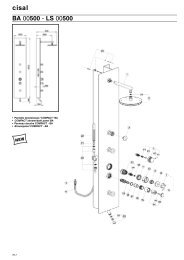
GBINTRODUCTORY INFORMATIONThe thermostatic mixers are suitable for hot water supplied bypressure tanks.For operation with local electric or gas water heaters, ensure thatthese have a rating of at least 18 KW or 250 Kcal/min. For localgas heaters it is advisable to use equipment with an automaticregulation of the quantity of gas in relation to the water flow.WARNING: thermostatic mixers cannot be used withunpressurised hot water tanks.SPECIFICATIONS:- Minimum dynamic pressure . . . . . . . . . . . . 0,5 bar- Maximum working pressure (static) . . . . . . . 10 bar- Recommended working pressure (static) . . . . 1-5 bar(N.B. for pressures greater than 5 bar the installation of apressure reducer is recommended)- Maximum test pressure (static) . . . . . . . . . . 16 bar- Maximum hot water temperature . . . . . . . . 80 °C- Minimum hot water temperature . . . . . . . . +2 °Chigher than the temperatureof the required mixing water- Safety block . . . . . . . . . . . . . . . . . . . . . . . 38 °C- Hot water connection . . . . . . . . . . . . . . . . . red-left- Cold water connection . . . . . . . . . . . . . . . . blue-right- Flow rate at 38 °C . . . . . . . . . . . . . . . . . . . see diagramPRESSUREFLOW RATELS 00190 + HY <strong>00019</strong>BA 00190 + HY <strong>00019</strong>HA 00190 + HY <strong>00019</strong>HY 00190 + HY <strong>00019</strong>(without resistance)0,5 bar 23,7 l/min.1 bar 34,2 l/min.2 bar 49 l/min.3 bar 59 l/min.plug (7) (Fig.A).- Check the water-tightness of the joints (maximum testpressure is 16 bar, static).- When installation has been completed, circulate the waterand completely rotate the thermostatic mixer valve rod (1)both clockwise and anticlockwise (Fig.A).- Check that the filters are not chocked by material present inthe pipe work, as described in the MAINTENANCE section.- Finish the plastering and tiling.- Do not remove the protective polystyrene packing until theexternal parts have been installed.ATTENTION: It is always required the installation of aconcealed valve between the outlet of the mixed water andthe shower or feed point.INSTALLATION OF EXTERNAL PARTS(Fig. A)- Cut the polystyrene protection at tiles level (Fig. C).- Seal any holes in the wall so that they are watertight tospray water (Fig. D).- Mount the covering escutcheon (3) to the adapter (2).- Mount the complete escutcheon (4).- Mount the temperature adjustment knob (10), recognizable bythe trade-mark CISAL and by numerical references (Fig. A):LS00190/HY00190: screwing down the screw (11) andmounting the plate (12)BA00190: screwing down the screw (11),mounting the reduction (13) and thehandle (14) and screwing down thepin (15)HA00190:mounting the handle (14), thegasket (16), screwing down thescrew (11) and the plate (12).ATTENTION: In case of assembling of the temperatureadjustment knob, no calibration is required.OPERATIONThe temperature regulation is limited to 38 °C by means of atemperature control device. If a higher temperature isrequired, press the safety button (9) fitted to the temperatureregulation knob (Fig. A).MAINTENANCEWARNING: In the case of a risk of frost, empty the domesticsystem, fully open the stop valve and unscrew the nonreturnvalve and filter (5-6) in order to completely empty thethermostatic mixer (Fig. A).INSTALLATION OF CONCEALED PARTS- Thoroughly rinse the water feed pipes.- Make a suitable hole in the wall and insert the mixer withits polystyrene packaging.- Connect the mixer to the feed pipes. This made easier bythe twin-threaded left right connector (8) provisionallyscrewed down on the cold water side (Fig. B).ATTENTION! Do not solder the mixer to the pipe work.Note the depth of the fitting into the wall as indicated onthe sticker on the polystyrene packing- the MIN. andMAX. points refer to the finished wall, including tiling.- Close the unused mixed water outlet joint with the screwREMOVING THE NON-RETURN VALVE (5) AND FILTER (6)(Fig. A)- Turn off the hot and cold inlets.- Empty the mixer of water by opening the stop valve.- Remove the knob (10):LS00190/HY00190: removing the plate (12) andunscrewing the screw (11)BA00190:unscrewing the pin (15), removingthe handle (14), the reduction (13)and unscrewing the screw (11)HA00190:unscrewing the plates (12), thescrews (11), removing the gaskets(16) and the handle (14).- Remove the escutcheon (4).- Unscrew the non-return valve (5) using a wide-bladed screwdriver or a 17 mm. hexagonal tubular spanner.8