Instr Manual: EXT Compound Molecular Pumps: EXT70H ... - Edwards
Instr Manual: EXT Compound Molecular Pumps: EXT70H ... - Edwards
Instr Manual: EXT Compound Molecular Pumps: EXT70H ... - Edwards

You also want an ePaper? Increase the reach of your titles
YUMPU automatically turns print PDFs into web optimized ePapers that Google loves.
Declaration of ConformityWe, BOC <strong>Edwards</strong>,Manor Royal,Crawley,West Sussex RH10 2LW. UKdeclare under our sole responsibiliry that the product(s)<strong>EXT</strong> <strong>Compound</strong> <strong>Molecular</strong> <strong>Pumps</strong>:<strong>EXT</strong>70H/|SO63 8722-21-000 <strong>EXT</strong>70HiilSO63 8722-29-400<strong>EXT</strong>70H/CF63 8722-22-000 <strong>EXT</strong>250H/|SO100 8740-01-000/8740-04-000<strong>EXT</strong>70H/NW40 8722-73-000 <strong>EXT</strong>250H/100CF 8740-02-000<strong>EXT</strong>70Hi|SO100 8722-25-000 <strong>EXT</strong>250H/ISO100 8740-03-000<strong>EXT</strong>T0Hi/CF63 24V 8753-02-000 <strong>EXT</strong>70H/ISO63 8772-27-000<strong>EXT</strong>T0Hi/|SO63 NW25/NW16 8722-30-000to which this declaration relates is in conformity with the following standard(s)or other normative document(s):EN lSOl 2100-2:2003 Safety of machinery. Basic concepts, general principals for design.Technical principals.EN61010-1: 2001 safety requirements for electrical equipment for measurement,Control and laboratory use. General requirements.xEN1012-2;1997 Compressors and vacuum pumps. Safety requirements. Vacuum pumps.EN61326: 19971 Electrical equipment for measurement, control and laboratory use.+ A1:: 1998 + A2:2001 EMC requirements.(lndustrial Location,Class B Emissions)* The pumps comply with EN51010-1 (2001) when installed in accordance with the instructionmanual supplied with the pumps.teNgtgZ0 lmmunity classification is dependent on the controller (see the controller manualfor details).following the provisions of;73l023lEEC89l336lEEC98l37lECLow Voltage Directive.Electromagnetic Compatibility Directive.Machinery Safety Directive.IlT'Ll,A-_I DCcerncgt\lcnr\r sgrfi€|+4hiaIo=Dr J. D. Watson, Technical DireaorVacuum Equipment and fuhoust Monagement Produd DivisionsDote ond PlaceThis product hos been manufactured under o quoliry system regrstered to lSO9001NooON^WBOC EDWARDS
CONTENTSSection Title Page1 INTRODUCTION 11.1 Scope and definitions 11.2 General description 21.3 Vent options and vent control 52 TECHNICAL DATA 62.1 General 62.2 Pumping media 62.2.1 <strong>Pumps</strong> without gas purge 72.2.2 <strong>Pumps</strong> with gas purge (<strong>EXT</strong>250H and <strong>EXT</strong>250Hi only) 72.3 Vent gas specification and vent control data 72.4 Purge gas specification (<strong>EXT</strong>250H and <strong>EXT</strong>250Hi only) 72.5 Cooling-water 82.6 Materials exposed to gases pumped 113 INSTALLATION 143.1 Unpack and inspect 143.2 Typical installation 143.3 Connect to the vacuum system 173.3.1 Inlet-screen 173.3.2 Mechanical fixing 173.3.3 Base mounting 183.3.4 Inlet connection and orientation 183.3.5 Backing connection 193.3.6 Interstage connection (<strong>EXT</strong>70Hi and <strong>EXT</strong>250Hi only) 193.4 Vent-valve connection and control 193.5 Purge gas connection (<strong>EXT</strong>250H and <strong>EXT</strong>250Hi only) 203.5.1 Connect the purge gas 203.5.2 Recommended purge gas flow 213.6 Electrical installation 213.6.1 EXC Controller 213.6.2 EXDC Drive Module 213.7 Cooling 223.7.1 Introduction 223.7.2 Forced-air cooling 223.7.3 Water-cooling 22Ipsitech 8204 (D) - 20054 OPERATION 244.1 Start-up 244.2 Stand-by 254.3 Shut-down 254.4 Safety interlocks and control system 254.5 Bakeout 265 MAINTENANCE 275.1 Introduction 275.2 Bearing life 27<strong>EXT</strong> <strong>Compound</strong> <strong>Molecular</strong> <strong>Pumps</strong>i
Section Title Page5.3 Rotor life 275.4 Clean the pump 285.5 Fault finding 286 STORAGE AND DISPOSAL 336.1 Storage 336.2 Disposal 337 SERVICE, SPARES AND ACCESSORIES 347.1 Introduction 347.2 Service 347.3 Spares 347.3.1 ISX inlet-screen 347.3.2 Inlet-strainer (<strong>EXT</strong>250Hi pump only) 347.3.3 WCX water-cooler 357.3.4 Inlet-flange seals 357.4 Accessories 357.4.1 Installation 357.4.2 EXC Controller 357.4.3 Pump-to-controller cable 357.4.4 EXDC Drive Modules 367.4.5 BX bakeout band 367.4.6 FL20K foreline trap 367.4.7 TAV vent-valve and vent-port adaptor 367.4.8 ACX air-cooler 387.4.9 Vibration isolators 387.4.10 PRX purge-restrictor 387.4.11 VRX vent-restrictor 387.4.12 <strong>EXT</strong>70H/ISO63 interstage-port accessory kit 39RETURN OF BOC EDWARDS EQUIPMENTIllustrationsFigure Title Page1 Cross-section view of <strong>EXT</strong>70H pump 32 Cross-section view of <strong>EXT</strong>250H pump 43 Maximum allowed rate of pressure rise during venting 84 <strong>EXT</strong>70H dimensions (mm) 125 <strong>EXT</strong>250H dimensions (mm) 136 Typical pumping system with an <strong>EXT</strong>70H or <strong>EXT</strong>250H pump 157 Typical pumping system with an <strong>EXT</strong>70Hi or <strong>EXT</strong>250Hi pump 168 Correct installation of the inlet-screen 179 Installation of optional accessories (and spares): <strong>EXT</strong>250Hi shown 37ii<strong>EXT</strong> <strong>Compound</strong> <strong>Molecular</strong> <strong>Pumps</strong>
This page intentionally blank.iv<strong>EXT</strong> <strong>Compound</strong> <strong>Molecular</strong> <strong>Pumps</strong>
1 INTRODUCTION1.1 Scope and definitionsThis manual provides installation, operation and maintenance instructions for the BOC<strong>Edwards</strong> <strong>EXT</strong>70H, <strong>EXT</strong>70Hi, <strong>EXT</strong>250H and <strong>EXT</strong>250Hi <strong>Compound</strong> <strong>Molecular</strong> <strong>Pumps</strong>. You mustuse the <strong>Pumps</strong> as specified in this manual. You cannot purchase an <strong>EXT</strong>70Hi pump; an <strong>EXT</strong>70Hipump is an <strong>EXT</strong>70H/ISO63 pump fitted with an interstage-port accessory: see Section 7.The <strong>EXT</strong> <strong>Compound</strong> <strong>Molecular</strong> <strong>Pumps</strong> are designed for use with a BOC <strong>Edwards</strong> EXCTurbomolecular Pump Controller (abbreviated to EXC Controller in the remainder of thismanual) or an EXDC Turbomolecular Pump Drive Module (abbreviated to EXDC Drive Modulein the remainder of this manual). Read this manual and the instruction manual supplied withyour EXC Controller or EXDC Drive Module before you attempt to install or operate theequipment. The instruction manual supplied with your EXC Controller or EXDC Drive Modulecontains details of how to set up a pumping system and how to control accessories such as anair-cooler, vent-valve and bakeout band.Important safety information in this manual is highlighted as WARNING and CAUTIONinstructions; you must obey these instructions. The use of WARNINGS and CAUTIONS isdefined below.WARNINGWarnings are given where failure to observe the instruction could result in injury or deathto people.CAUTIONCautions are given where failure to observe the instruction could result in damage to theequipment, associated equipment and process.In accordance with the recommendations of EN61010, the following warning symbols mayappear on the pump or its accessories:Caution - refer toaccompanying documents.Caution - hot surface.Caution - risk of electric shock.Protective conductor terminal.The units used throughout this manual conform to the SI international system of units ofmeasurement. Also throughout this manual, wherever flow rates are specified, the abbreviation‘sccm’ is used to mean ‘standard cm 3 min -1 : this is a flow of 1 cm 3 min -1 at an ambienttemperature of 0 o C and a pressure of 1013 mbar (1.013 x 10 5 Pa).<strong>EXT</strong> <strong>Compound</strong> <strong>Molecular</strong> <strong>Pumps</strong> 1
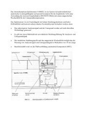
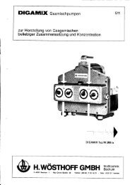
1.2 General descriptionThe <strong>EXT</strong>70H, <strong>EXT</strong>70Hi, <strong>EXT</strong>250H and <strong>EXT</strong>250Hi pumps are compound vacuum pumps thatcombine a turbomolecular pump and a drag pump on a single shaft. The internal structures ofthe <strong>EXT</strong>70H and <strong>EXT</strong>250H pumps are shown in Figures 1 and 2.The turbomolecular pump is made from a multi-stage axial-flow turbine which is optimised foroperation in molecular flow conditions. The drag pump is made from pumping channelsformed by plane rotating disks. The drag pump is designed for operation at higher pressuresthan conventional turbomolecular pumps.The light alloy rotor (13) is machined from one piece to form the angled blades of theturbomolecular pump and the disks of the drag pump. The rotor blades rotate between angledstator blades (12) which are supported by spacer rings (11). The rotor and stator blades have anopen structure at the pump inlet, and a more closed structure at the outlet. This configurationgives an optimum combination of pumping speed and compression when pumping gases ofboth high and low molecular weight. For the blades to be effective, their speed must be close tothe thermal velocity of the gas. The rotor of the <strong>EXT</strong>70H/Hi therefore rotates at up to90000 r min -1 , and the rotor of the <strong>EXT</strong>250H/Hi therefore rotates at up to 60000 r min -1 .Gas from the inlet is compressed through each of the bladed stages of the turbomolecular pumpand transferred to the drag pump. In the drag pump stages, the gas is further compressed as it ispumped around the channels formed by the separation of the disks. The inlet and outlet of eachchannel is separated by a close-running seal which diverts the gas through a port to the nextchannel, or to the pump outlet.The rotating assembly is supported at the inlet end by a frictionless magnetic bearing (3) and by aprecision ceramic ball bearing (8) at the outlet end. The ball bearing is lubricated from an oilreservoir and wick mechanism (9).The <strong>EXT</strong> pump is supplied with an inlet-screen (2) fitted in the bore of the inlet-flange. The<strong>EXT</strong>250Hi pump is also supplied with an inlet-strainer which fits in the interstage-port. Theinlet-screen and inlet-strainer protect the pump against damage which would be caused bydebris which enters the pump. The inlet-screen also protects you from the sharp blades in thepump.The <strong>EXT</strong> pump has a vent-port that you can use to vent the pump and your vacuum system toatmospheric pressure. The vent-port introduces vent gas part way up the pump rotor; thisensures maximum cleanliness. The pump is supplied with a manual vent-valve fitted to thevent-port. As described in Section 3.4, you can replace the manual vent-valve with a TAV5 orTAV6 solenoid-operated vent-valve (available as an accessory: see Section 7).The <strong>EXT</strong>250H and <strong>EXT</strong>250Hi pumps have a purge-port (Figure 5, item 4) in the motor andbearing housing chamber. In order to protect the bearing lubricant from the effects of highoxygen concentrations, you can introduce an inert purge gas through the purge-port. You can fitan optional vent-port adaptor and purge restrictor to the purge-port to control the flow rate ofthe purge gas and to filter the gas supply (see Section 7).2 <strong>EXT</strong> <strong>Compound</strong> <strong>Molecular</strong> <strong>Pumps</strong>
1. Inlet-flange2. Inlet-screen3. Magnetic bearing4. Safety bearing5. Envelope6. Shaft7. DC motor8. Ball bearing9. Oil reservoir10. Drag stage11. Spacer ring12. Stator13. RotorFigure 1 - Cross-section view of <strong>EXT</strong>70H pump<strong>EXT</strong> <strong>Compound</strong> <strong>Molecular</strong> <strong>Pumps</strong> 3
The <strong>EXT</strong>250Hi pump has an interstage-port between the turbomolecular and drag stages. Ifrequired, you can fit an interstage-port accessory to an <strong>EXT</strong>70H/ISO63 pump to upgrade it to an<strong>EXT</strong>70Hi pump (see Section 7). You can use the interstage-port on <strong>EXT</strong>70Hi and <strong>EXT</strong>250Hipumps to pump a separate chamber of your vacuum system or to back another turbomolecularpump:If the <strong>EXT</strong>70Hi pump operates with an outlet pressure of less than 5 mbar (500 Pa) and aninterstage inlet flow of less than 100 sccm (1.69 mbar l s -1 , 169 Pa l s -1 ), or with an outletpressure of less than 10 mbar (1000 Pa) and an interstage inlet flow of less than 50 sccm(0.84 mbar l s -1 ,84Pals -1 ), the vacuum performance at the turbomolecular pump-inlet isindependent of the interstage operating conditions.If the <strong>EXT</strong>250Hi pump operates with an outlet pressure of less than 5 mbar (500 Pa) and aninterstage inlet flow of less than 70 sccm (1.17 mbar l s -1 , 117 Pa l s -1 ), the vacuumperformance at the turbomolecular pump-inlet is independent of the interstage operatingconditions.If you use an EXC Controller to control the <strong>EXT</strong> pump, the electrical connection between the <strong>EXT</strong>pump and the EXC Controller is by the 19-way connector on the pump and a pump-to- controllercable. The cable is a separate item and is available in a choice of lengths (see Section 7 for details).If you use an EXDC Drive Module to control the <strong>EXT</strong> pump, the EXDC Drive Module is fitteddirectly to the 19-way connector on the pump.The <strong>EXT</strong> pump may be air-cooled using an optional air-cooler accessory, or water-cooled bypassing water through the water-cooler provided. Two riffled hose connectors are provided forconnection of your cooling-water supply and return pipelines. A thermal sensor monitors thetemperature of the motor and the pump-body.1.3 Vent options and vent controlTo maintain the cleanliness of your vacuum system, we recommend that, whenever you switchthe pump off, you vent the pump (or vacuum system) when the speed of the <strong>EXT</strong> pump isbetween full rotational speed and 50% of full rotational speed. At and above 50% of fullrotational speed, the rotor spins fast enough to suppress any backstreaming of hydrocarbon oilfrom your backing pump.However, if you vent the pump when it is at full rotational speed and the rate of pressure rise istoo high, the pump life may be reduced. We therefore recommend that you either limit the rate ofpressure rise (see Figure 3), or only open the vent-valve after the <strong>EXT</strong> pump speed has fallen to50% of full rotational speed.The rate of pressure rise cannot be controlled by the manual vent-valve, so if you use the manualvent-valve, you must only open the vent-valve after the <strong>EXT</strong> pump speed has fallen to 50% of fullrotational speed.If you use a TAV5 vent-valve, but you cannot limit the rate of pressure rise, you must only openthe vent-valve after the speed of the <strong>EXT</strong> pump has fallen to 50% of full rotational speed. If youuse the EXC Controller to control your TAV5 vent-valve, configure the EXC Controller to selectthis option: refer to Section 3.4 for more information. The EXC Controller is factory set to ventwhen the <strong>EXT</strong> pump is at 50% of full rotational speed after you select Stop.<strong>EXT</strong> <strong>Compound</strong> <strong>Molecular</strong> <strong>Pumps</strong> 5
2 TECHNICAL DATA2.1 GeneralPerformance See Tables 1 and 2Cooling, noise and electrical data See Table 3Dimensions See Figures 4 and 5Maximum inlet-flange temperature100 o CMaximum magnetic field5 mTInstallation category EN61010 part 1, Category 1Pollution degree EN61010 part 1, Category 2Equipment typeFixed equipment, for indoor use only2.2 Pumping mediaWARNINGVent dangerous gases and gas mixtures safely. Do not expose people to these gases.WARNINGDo not use <strong>EXT</strong> pumps to pump explosive gas mixtures as the pumps are not suitable forthis purpose.WARNINGOn <strong>EXT</strong>70Hi and <strong>EXT</strong>250Hi pumps, gas pumped through the interstage-port will mix withgas pumped through the pump-inlet. Ensure that the gases will not react or combine toform dangerous gases and substances.CAUTIONDo not use an <strong>EXT</strong> to pump gases containing more than 20% oxygen unless the pump isgas purged. If you do, the lubricant will polymerise and the pump will fail prematurely.CAUTIONDo not use an <strong>EXT</strong> to pump mercury vapour and do not allow mercury (for example, froma Mcleod gauge) to come into contact with the pump. If you do, the pump rotor maycorrode and fail.Note that concentrations of gases may be modified by the compression of the pump.6 <strong>EXT</strong> <strong>Compound</strong> <strong>Molecular</strong> <strong>Pumps</strong>
2.2.1 <strong>Pumps</strong> without gas purgeThe pumps are designed to pump the following residual gases normally used in high-vacuumsystems : Air Carbon monoxide Neon Ethane Methane Nitrogen Krypton Argon Propane Carbon dioxide Helium Hydrogen ButaneYou can use the pumps to pump oxygen and water vapour, subject to the following conditions : Oxygen The oxygen concentration must be less than 20% by volume. Water vapour You must ensure that vapour does not condense inside the pump;refer to Section 3.7.3.If you wish to pump a gas not in the list above, contact your supplier for advice. If you do notcontact your supplier, you may invalidate the warranty on the pump. The pumps are not suitablefor pumping aggressive or corrosive gases.2.2.2 <strong>Pumps</strong> with gas purge (<strong>EXT</strong>250H and <strong>EXT</strong>250Hi only)When purged with an inert gas, the pumps can be used to pump oxygen in concentrations above20% by volume.2.3 Vent gas specification and vent control dataAlthough the pump may be vented to atmospheric air, high relative humidity of the air maygreatly increase the subsequent pumping time. To reduce pump-down times you should ventthe pump with dry, clean gases.Vent gasDry air, nitrogen, argon or otherinert gasesMaximum dew point at atmospheric pressure -22 o CMaximum size of particulates1 mMaximum concentration of oil0.1 parts per millionMaximum allowed rate of pressure rise See Figure 32.4 Purge gas specification (<strong>EXT</strong>250H and <strong>EXT</strong>250Hi only)Purge gasDry nitrogen, argon or otherinert gasesMaximum dew point at atmospheric pressure -22 o CMaximum size of particulates1 mMaximum concentration of oil0.1 parts per millionAllowable purge gas flow (when required) 20 to 100 sccm (0.33 to 1.67 mbar l s -1 ,33 to 167 Pa l s -1 )Recommended purge gas flow 25 sccm (0.42 mbar l s -1 , 42 Pa l s -1 )Maximum allowable purge gas supply pressure 2 bar (gauge) ; 29 psig, 3 x 10 5 Pa<strong>EXT</strong> <strong>Compound</strong> <strong>Molecular</strong> <strong>Pumps</strong> 7
Figure 3 - Maximum allowed rate of pressure rise during venting: system pressure(Pa/mbar, with the backing pump isolated) against time (s),with the pump initially at full rotational speed2.5 Cooling-waterThe following cooling-water specification corresponds to a typical high-quality drinking waterspecification. Check with your water supply authority if you are in doubt about the quality ofyour supply.QualityMechanically clean and opticallyclear with no deposits or turbidity.pH value 6.0 to 8.0Maximum calcium carbonate concentration 75 parts per millionMaximum chloride concentration100 parts per millionMinimum oxygen concentration4 parts per millionMinimum water-cooling flow rate ( at 15 o C) 15 l h -1Water temperature See Table 3Maximum water pressure5 bar (gauge), 73.5 psig, 6 x 10 5 Pa8 <strong>EXT</strong> <strong>Compound</strong> <strong>Molecular</strong> <strong>Pumps</strong>
Parameter <strong>EXT</strong>70H/ISO63 <strong>EXT</strong>70H/63CF <strong>EXT</strong>70H/NW40 NotesMass 2.8 kg 4.7 kg 2.8 kgInlet-flange DN63ISO-K DN63CF DN40NWOutlet-flange DN16NW DN16NW DN16NW111Vent-port/ 8inch BSP / 8inch BSP / 8inch BSPInterstage-port DN25NW ▲ - -Purge-port - - -Inlet pumping speed# ‡N 265 l s -1 65 l s -1 52 l s -1 Pb < 10 mbar (1000 Pa)Qi < 50 sccm(0.84 mbar l s -1 ,84 Pa l s -1 )He # ‡ 60 l s -1 60 l s -1 53 l s -1 Pb < 5 mbar (500 Pa)Qi = 0H 2# ‡ 50 l s -1 50 l s -1 46 l s -1 Pb < 2 mbar (200 Pa)Qi = 0Inlet compression ratioN 2# > 1 x 10 8 > 1 x 10 8 > 1 x 10 8 Pb < 10 mbar (1000 Pa)He # 4 x 10 5 4 x 10 5 4 x 10 5 Pb < 3 mbar (300 Pa)H 2# 3 x 10 4 3 x 10 4 3 x 10 4 Pb < 1 mbar (100 Pa)Interstage pumping speed ‡N 2#Ultimate pressure *Minimum backing pumpdisplacementMaximum continuous inletpressure §water-cooling at 15 o C §air-cooling at 35 o C §Recommended backingpump ✝Operating attitude6 l s -1 - - Pb = 5 mbar (500 Pa)Qi = 100 sccm(1.69 mbar l s -1 ,169 Pa l s -1 )Qp = 0 sccm< 5 x 10 -9 mbar< 5 x 10 -7 Pa< 5 x 10 -10 mbar< 5 x 10 -8 Pa< 5 x 10 -9 mbar< 5 x 10 -7 Pa0.6 m 3 h -1 0.6 m 3 h -1 0.6 m 3 h -19 x 10 -1 mbar,90 Pa9 x 10 -2 mbar,9 Pa9 x 10 -1 mbar,90 Pa9 x 10 -2 mbar,9 Pa9 x 10 -1 mbar,90 Pa9 x 10 -2 mbar,9 PaE2M0.7 E2M0.7 E2M0.7Vertical and upright through to horizontal 2 oNominal rotational speed 90000 r min -1 90000 r min -1 90000 r min -1Standby rotational speed 63000 r min -1 63000 r min -1 63000 r min -1Starting time to 90% speed 90 sec 90 sec 90 sec▲ Optional accessory‡Pumping speeds are without inlet-screen or inlet-strainer. Inlet-screens and inlet-strainers reduce speed byapproximately 10%.#Pb = backing pressure, Qi = flow through the interstage-port (<strong>EXT</strong>70Hi only), Qp = flow through pump-inlet* Ultimate pressure 48 hours after bakeout with 2-stage rotary vane backing-pump.§Above this pressure, rotational speed drops below nominal.✝ A larger backing-pump may be required for maximum throughput.Table 1 - <strong>EXT</strong>70H/<strong>EXT</strong>70Hi technical data<strong>EXT</strong> <strong>Compound</strong> <strong>Molecular</strong> <strong>Pumps</strong> 9
Parameter <strong>EXT</strong>250H <strong>EXT</strong>250Hi NotesMass 8.0 kg 8.0 kgInlet-flangeDN100ISO-K/ DN100ISO-KDN100CFOutlet-flange DN25NW DN25NW11Vent-port/ 8inch BSP / 8inch BSPInterstage-port - DN25NW11Purge-port/ 8inch BSP / 8inch BSPInlet pumping speed# ‡N 2220 l s -1 220 l s -1 Pb < 5 mbar (500 Pa)Qi < 70 sccm (1.18 mbar l s -1 ,118 Pa l s -1 )He # ‡ 230 l s -1 230 l s -1 Pb < 1 mbar (100 Pa)Qi = 0 sccmH 2# ‡ 180 l s -1 180 l s -1 Pb < 0.5 mbar (50 Pa)Qi = 0 sccmInlet compression ratioN 2# > 2 x 10 7 > 2 x 10 7 Pb = 5 mbar (500 Pa)He # > 1.6 x 10 4 > 1.6 x 10 4 Pb = 2 mbar (200 Pa)#H 21500 1500 Pb = 1 x 10 -2 mbar (1 Pa)Interstage pumping speed ‡‡Ultimate pressure *#N 2- 8 l s -1 Pb = 5 mbar (500 Pa)Qi = 100 sccm (1.69 mbar l s -1 ,169 Pa l s -1 )Qp < 20 sccm (0.33 mbar l s -1 ,33 Pa l s -1 )N 2# - 11 l s -1 Pb = 5 mbar (500 Pa)Qi = 240 sccm (4.5 mbar l s -1 ,405 Pa l s -1 )Qp = 0 sccmMinimum backing pumpdisplacementMaximum continuous inletpressure §water-cooling at 15 o C §< 5 x 10 -9 mbar< 5 x 10 -7 Pa< 5 x 10 -9 mbar< 5 x 10 -7 Pa0.6 m 3 h -1 0.6 m 3 h -13 x 10 -1 mbar,30 Pa3 x 10 -1 mbar,30 Paair-cooling at 35 o C § 3 x 10 -2 mbar, 3 Pa 3 x 10 -2 mbar, 3 PaRecommended backing pump ✝ RV3 RV3Operating attitudeVertical and upright through tohorizontal 2 oNominal rotational speed 60000 r min -1 60000 r min -1Standby rotational speed 42000 r min -1 42000 r min -1Starting time to 90% speedEXC100E/L, EXDC80 190 sec 190 secEXC120 130 sec 130 secEXC300, EXDC160 100 sec 100 secPumping speeds are without inlet-screen or inlet-strainer (<strong>EXT</strong>250Hi only). Inlet-screens and inlet-strainers reducespeed by approximately 10%.#Pb = backing pressure, Qi = flow through the interstage-port (<strong>EXT</strong>250Hi only), Qp = flow through pump-inlet* Ultimate pressure 48 hours after bakeout with 2-stage rotary vane backing-pump.§Above this pressure, rotational speed drops below nominal.✝ A larger backing-pump may be required for maximum throughput.Table 2 - <strong>EXT</strong>250H/<strong>EXT</strong>250Hi technical data10 <strong>EXT</strong> <strong>Compound</strong> <strong>Molecular</strong> <strong>Pumps</strong>
Cooling methodForced-air/waterAmbient air temperature (forced-air cooling) 0 - 35 o CWater temperature (water-cooling)10 - 20 o CNoise level (at 1 metre)< 50 dB(A)Recommended controllerEXC120/EXC100E/EXC100LEXC120/100E/100L maximum VA input 250 VA with bakeout bandEXC120/100E/100L apparent power 60 VA typical operating conditionsOther compatible controllerEXC300EXC300 maximum VA input 480 VA with bakeout bandEXC300 apparent power 60 VA typical operating conditionsCompatible drive modulesEXDC80, EXDC160EXDC80 maximum power input93 WEXDC160 maximum power input187 WQuiescent apparent power10 VATable 3 - Cooling, noise and electrical data (all pumps)2.6 Materials exposed to gases pumpedThe following materials and component types are exposed to the gases pumped: aluminiumalloys, stainless steels, glass filled PTFE (polytetrafluoroethylene)*, PEEK (polyetheretherketone)450G ✝ , fluoroelastomer and nitrile ‘O’ rings, hydrocarbon lubricant, felt, rare earthmagnets, silicon nitride and phenolic resin.* <strong>EXT</strong>250H/Hi pumps only.✝ <strong>EXT</strong>70H/Hi pumps only.<strong>EXT</strong> <strong>Compound</strong> <strong>Molecular</strong> <strong>Pumps</strong> 11
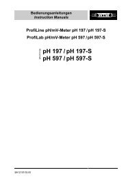
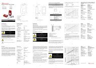
1. Vent-valve2. Backing-port3. Cooling-water connectors4. Earth (ground) screw5. Electrical supply connector6. Allowance for right-angle cable connectorFigure 4 - <strong>EXT</strong>70H dimensions (mm)12 <strong>EXT</strong> <strong>Compound</strong> <strong>Molecular</strong> <strong>Pumps</strong>
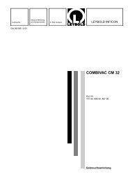
1. Interstage-port (<strong>EXT</strong>250Hi only)5. Electrical supply connector2. Vent-valve6. Backing-port3. Earth (ground) screw7. Cooling-water connectors4. Purge-plug in purge-port8. Allowance for right-angle cable connectorFigure 5 - <strong>EXT</strong>250H dimensions (mm)<strong>EXT</strong> <strong>Compound</strong> <strong>Molecular</strong> <strong>Pumps</strong> 13
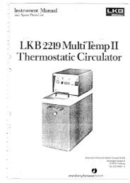
3 INSTALLATIONWARNINGSafely route all vacuum, vent/purge gas and cooling-water pipelines, and all electricalcables and wires, so that people cannot trip over them.3.1 Unpack and inspectThe pump is packed to prevent damage in transit. Take care when you unpack the pump toavoid excessive shocks which could damage the bearings and reduce the life of the pump. Thepump is supplied with the inlet and outlet sealed to prevent entry of dust and vapour. Do notremove these seals until you are ready to install the pump on your vacuum system.Remove all packing materials and check the pump. If the pump is damaged, notify your supplierand the carrier in writing within three days; state the Item Number of the pump together withyour order number and your supplier’s invoice number. Retain all packing materials forinspection. Do not use the pump if it is damaged.Check that your package contains the items listed in Table 4. If any of these items is missing,notify your supplier in writing within three days.Qty Description Check (✓)1 <strong>EXT</strong> turbomolecular pump ❏1 Inlet seal (trapped ‘O’ ring, Co-Seal or copper compression gasket) ❏1 Inlet-strainer (<strong>EXT</strong>250Hi only, fitted in the interstage-port) ❏Table 4 - Checklist of itemsIf the pump is not to be used immediately, store the pump in suitable conditions as described inSection 6.1.Do not discard the packing materials; retain them to repack the pump when you return it forservice.3.2 Typical installationA typical pumping system with an <strong>EXT</strong>250H pump is shown in Figure 6. A typical pumpingsystem with an <strong>EXT</strong>250Hi pump is shown in Figure 7. When necessary, purge the <strong>EXT</strong>250H/Hipump with inert gas as described in Section 3.5.Typical pumping systems with an <strong>EXT</strong>70H and <strong>EXT</strong>70Hi pumps will be as shown in Figures 6and 7, but without the gas purge components (15, 16).The accessories available for these <strong>EXT</strong> pumps are detailed in Section 7; the accessories areshown in Figure 9.14 <strong>EXT</strong> <strong>Compound</strong> <strong>Molecular</strong> <strong>Pumps</strong>
1. Vacuum system 7. Vacuum gauge 13. EXC Controller2. High-vacuum gauge 8. Flexible bellows 14. Air-cooler3. Vibration isolator 9. Foreline trap 15. PRX10 purge restrictor *4. Inlet-screen 10. Rotary backing-pump 16. Regulated purge gas supply *5. <strong>EXT</strong> pump 11. Mist filter 17. Vent-valve6. Backing valve 12. Cooling-water connectors 18. Alternative position for vent-valve* <strong>EXT</strong>250H onlyFigure 6 - Typical pumping system with an <strong>EXT</strong>70H or <strong>EXT</strong>250H pump<strong>EXT</strong> <strong>Compound</strong> <strong>Molecular</strong> <strong>Pumps</strong> 15
1. Vacuum chamber 12. High-vacuum gauge3. Vibration isolator4. Inlet-screen5. <strong>EXT</strong> pump6. Not used7. Vacuum gauge8. Flexible bellows9. Foreline trap10. Rotary backing-pump11. Mist filter12. Cooling-water connectors13. EXC Controller14. Air-cooler15. PRX10 purge restrictor *16. Regulated purge gas supply *17. Vent-valve18. Alternative position for vent-valve19. Vacuum chamber 220. Inlet-strainer21. Interstage-port* <strong>EXT</strong>250Hi onlyFigure 7 - Typical pumping system with an <strong>EXT</strong>70Hi or <strong>EXT</strong>250Hi pump16 <strong>EXT</strong> <strong>Compound</strong> <strong>Molecular</strong> <strong>Pumps</strong>
3.3 Connect to the vacuum systemWARNINGInstall the pump in the vacuum system before you connect the EXC Controller or EXDCDrive Module. This will ensure that the pump cannot operate and injure people duringinstallation.3.3.1 Inlet-screenDo not remove the inlet-screen unless you can be sure that there is no danger that debris can fallinto the pump. In order to avoid the danger of injury from the rotor blades, do not remove theinlet-screen until you are ready to mount the pump onto your system. If the screen is removed,the pumping speed will increase by approximately 10%. It is not possible to remove theinlet-screen from a pump with an NW inlet-flange.To remove the inlet-screen from a pump with an ISO or CF inlet-flange, carefully extract it fromthe inlet-flange using a bent wire hook. To replace a screen which has been removed, install it asshown in Figure 8, with the BOC <strong>Edwards</strong> logo uppermost. Ensure that the dimples on the rimof the screen engage in the groove in the pump flange. If necessary, gently bend the tags of thescreen outwards to ensure a tight fit.1. <strong>EXT</strong> inlet-flange2. Inlet-screenFigure 8 - Correct installation of the inlet-screen3.3.2 Mechanical fixingWARNINGDo not operate the <strong>EXT</strong> pump until it is securely fixed. If the pump seizes, the storedenergy of the rotor can cause rapid movement of the pump, which may cause damage andinjury to people.There are two ways in which the <strong>EXT</strong> pump can be securely fixed. Ideally, the <strong>EXT</strong> pump shouldbe securely fixed by its inlet-flange to a rigid, firmly fixed vacuum system: see Section 3.3.4. If thisis not possible because of the nature of the vacuum system, the base of the <strong>EXT</strong> pump must besecurely fixed to a firm support: see Section 3.3.3.<strong>EXT</strong> <strong>Compound</strong> <strong>Molecular</strong> <strong>Pumps</strong> 17
3.3.3 Base mountingEnsure that the base of the pump is securely fixed to a firm support (refer to Figures 4 and 5 forthe fixing hole details). If the pump supports the weight of the vacuum system, the mass of thevacuum system must be no more than 10 kg for an <strong>EXT</strong>70H/Hi pump, or no more than 20 kg foran <strong>EXT</strong>250H/Hi pump.You must also ensure that your mounting method meets the following requirements, so that the<strong>EXT</strong> pump will remain secure in the event of a pump seizure:The support mounting must be able to withstand a destructive torque of 333 Nm for an<strong>EXT</strong>70H/Hi pump or 620 Nm for an <strong>EXT</strong>250H/Hi pump.Fit cap-head fixing screws through the tapped fixing-holes in the base of the pump (seeFigures 4 and 5): use M4 screws for an <strong>EXT</strong>70H/Hi pump, and use M5 screws for an<strong>EXT</strong>250H/Hi pump.The fixing screws must comply with ISO 898-1, with a strength class of 12.9 (nominal tensilestrength 1200 MPa).The fixing screw engagement length must be 6 mm or more.Tighten the fixing screws to a torque of 6 Nm (0.61 kgf m) on <strong>EXT</strong>70H/Hi pumps, and to atorque of 12 Nm (1.22 kgf m) on <strong>EXT</strong>250H/Hi pumps.3.3.4 Inlet connection and orientationThe <strong>EXT</strong> pump can be fixed to the vacuum system by the inlet-flange. The pump can be mountedin any attitude from vertical and upright through to horizontal ( 2 o ). If the pump is mountedhorizontally and you use a rotary vane pump to back the <strong>EXT</strong> pump, the backing port must pointvertically downwards (20 o ) to reduce the risk of contamination from the backing pump oil.Make sure that the pump-inlet and all components fitted to the pump-inlet are clean anddust-free. If the pump-inlet is not kept clean, the pump-down time may be increased.The inlet-connection of the <strong>EXT</strong> pump is a CF flange, an ISO flange or an NW flange:If the pump has a CF flange, use the copper compression gasket supplied with the pump anduse a full complement of bolts to connect the inlet-flange of the pump to the vacuum system.If the pump has an ISO flange, use the BOC <strong>Edwards</strong> trapped ‘O’ ring supplied with thepump and use a minimum of four claw clamps to connect the inlet-flange of the pump to thevacuum system. Ensure that each claw clamp is tightened to a torque of 10 Nm or more.Alternatively, use a rotatable collar and the trapped ‘O’ ring supplied with the pump toconnect the inlet-flange of the pump to the vacuum system; use a full complement of boltswith the rotatable collar.If the pump has an NW flange, use the Co-Seal supplied with the pump and a suitable NWclamp to connect the inlet-flange of the pump to the vacuum system.Ensure that no torque or other forces are transmitted to the pump from the vacuum system or theassociated pipelines.18 <strong>EXT</strong> <strong>Compound</strong> <strong>Molecular</strong> <strong>Pumps</strong>
If necessary, fit an inlet vibration isolator between the pump-inlet and the vacuum system: referto Section 7.4.9 for the Item Numbers, and refer to the instruction manual supplied with thevibration isolator for installation details. If you fit a vibration isolator, you must securely fix thebase of the <strong>EXT</strong> pump as described in Section 3.3.3.Note:The first time you pump down the system to vacuum, you must re-tighten the bolts which securethe inlet-flange.3.3.5 Backing connectionUse suitable vacuum tubing and connectors to connect the NW flange of the backing-port to yourbacking-pump. If necessary, use flexible pipe or bellows to reduce the transmission of vibrationfrom the backing-pump to the <strong>EXT</strong> pump.We recommend that you use a BOC <strong>Edwards</strong> EM or RV backing-pump. The minimum size of thebacking-pump required is given in Tables 1 and 2. You may have to use a larger backing-pump ifyou run the pump at a high inlet pressure or high throughput, or if you purge an <strong>EXT</strong>250H/Hipump with more than 25 sccm (0.42 mbar l s -1 , 42 Pa l s -1 ) of purge gas.Do not use the <strong>EXT</strong> pump with a backing pressure below 1 x 10 -4 mbar (1 x 10 -2 Pa). Lowerbacking pressures will increase the evaporation rate of the lubricating oil and so will reduce thelife of the bearings.3.3.6 Interstage connection (<strong>EXT</strong>70Hi and <strong>EXT</strong>250Hi only)Use suitable vacuum tube and connectors to connect the interstage-port to your vacuum systemor to the outlet flange of another turbomolecular pump (if you use the <strong>EXT</strong>70Hi or <strong>EXT</strong>250Hipump to back another turbomolecular pump). Leave the inlet-strainer in the interstage-port ofthe <strong>EXT</strong>250Hi pump, unless you are sure that debris cannot be drawn into the interstage-port.3.4 Vent-valve connection and controlWhen you design your system and when you install a vent-valve, take note of the information inSections 1.3 and 2.3. You can vent the <strong>EXT</strong> pump and your vacuum system by any of thefollowing methods:Use the manual vent-valve supplied.Use a TAV5 or TAV6 solenoid vent-valve accessory (see Section 7) in place of the manualvent-valve.Use a TAV5 or TAV6 solenoid vent-valve connected to a convenient flange on your vacuumsystem.Use an alternative valve connected to your vacuum system.If you use the manual vent-valve, you must open the vent-valve only after the <strong>EXT</strong> pump speedhas fallen to 50% of full rotational speed.If you use the TAV5 vent-valve, you can only vent the pump when it is at full speed if the vacuumsystem has a volume of 5 litres or more. If you use the TAV6 vent-valve, you can only vent thepump when it is at full speed if the vacuum system has a volume of 10 litres or more.<strong>EXT</strong> <strong>Compound</strong> <strong>Molecular</strong> <strong>Pumps</strong> 19
If the volume of your vacuum system is less than 5 litres when you use a TAV5 vent-valve, or ifthe volume of your vacuum system is less than 10 litres when you use a TAV6 vent-valve, youcan incorporate a suitable vent-restrictor (see Table 5) and vent the pump when it is at full speed.If you do not incorporate a vent-restrictor, you can use the EXC Controller to open the vent-valveafter the <strong>EXT</strong> pump speed has fallen to 50% of full rotational speed: do not select the EXCController ‘Vent On Stop’ option. Refer to the EXC Controller instruction manual for moreinformation.If you use another vent-valve, you must ensure that you have a suitable vent-restrictor fitted tosuit your vacuum system to limit the rate of pressure rise: refer to Table 5. If you do not fit asuitable vent-restrictor , you must open the vent-valve only after the speed of the <strong>EXT</strong> pump hasfallen to 50% of full rotational speed.If you connect the vent-valve to your vacuum system, select a point upstream of the <strong>EXT</strong> pumpto prevent backstreaming of oil from the backing pump. Do not connect the vent-valve to thebacking pipeline. Connect the inlet of the vent-valve to the vent gas supply (refer to Section 2.3for the vent gas specification).Note:If you use a vent-restrictor, you may find that the time required to vent your vacuum system isunacceptably long. You may be able to reduce the vent time if you use a vent-valve without avent-restrictor and wait until the pump speed has fallen to 50% of full rotational speed before youopen the vent-valve.Vacuum system volume (l)< 20< 10< 5< 2Orifice diameter (mm) 1.0 0.7 0.5 0.35Table 5 - Vent-restrictor orifice diameter (with atmosphericpressure at the inlet of the vent-valve)3.5 Purge gas connection (<strong>EXT</strong>250H and <strong>EXT</strong>250Hi only)3.5.1 Connect the purge gasIf you want to supply a purge gas to the pump, remove the manual purge-valve/plug fitted inthe purge-port, fit a vent-port adaptor (see Section 7.4) to the purge-port and connect your purgegas supply to the vent-port adaptor. Your purge gas must comply with the specification given inSection 2.4.You must limit the flow rate of the purge gas to the allowed range, also specified in Section 2.4.To limit the flow rate, use a flow controller or a pressure regulator and calibrated flow restrictor.The PRX10 purge restrictor accessory (see Section 7.4) is suitable for this purpose. Adjust thePRX10 as described in the instruction manual supplied with the accessory.20 <strong>EXT</strong> <strong>Compound</strong> <strong>Molecular</strong> <strong>Pumps</strong>
3.5.2 Recommended purge gas flowThe recommended purge gas flow for typical applications is 25 sccm (0.42 mbar l s -1 ,42Pals -1 ).This flow will protect the pump when you pump oxygen in concentrations above 20% byvolume.3.6 Electrical installationWARNINGYou must electrically bond the <strong>EXT</strong> pump to earth (ground): use the earth (ground) screwprovided on the pump (Figure 4, item 3 and Figure 5, item 4).Always make the electrical connections to the <strong>EXT</strong> pump after the pump has been installed onyour vacuum system.3.6.1 EXC ControllerThe EXC Controller provides the electrical supply to the <strong>EXT</strong> pump through the multiwaypump-to-controller cable. Connect and lock the bayonet-connectors at the ends of the cable to themating connectors on the pump and the EXC Controller.The EXC Controller is designed to allow a pumping system to be configured in a variety of ways,from a basic manually-operated system to a fully automatic system with remote control. Refer tothe EXC Controller instruction manual to complete the electrical installation.3.6.2 EXDC Drive ModuleFit the connector on the EXDC Drive Module directly to the 19-way connector on the <strong>EXT</strong> pump.The EXDC Drive Module is designed to allow a pumping system to be configured in a variety ofways. Refer to the EXDC Drive Module instruction manual to complete the electricalinstallation.<strong>EXT</strong> <strong>Compound</strong> <strong>Molecular</strong> <strong>Pumps</strong> 21
3.7 Cooling3.7.1 IntroductionCAUTIONYou must ensure that the pump is adequately cooled to prevent damage to the bearinglubricant.We recommend that wherever possible, you cool the pump by forced-air or water-cooling. Youmust use water-cooling in any of the following operating conditions: Backing pressure > 10 mbar (1000 Pa) and interstage flow > 20 sccm (0.3 mbar l s -1 ,30Pals -1 ). Backing pressure > 8 mbar (800 Pa) and interstage flow > 30 sccm (0.5 mbar l s -1 ,50Pals -1 ). Backing pressure > 5 mbar (500 Pa) and interstage flow > 80 sccm (1.3 mbar l s -1 , 130 Pa l s -1 ). Ambient temperature > 35 o C.When you use a bakeout band.In all other operating conditions, you can use forced-air cooling. If you use forced-air to cool thepump, you must ensure that there is an adequate supply of cooling-air to the pump.However, for light pumping duties, with ambient temperature < 30 o C and inlet-flangetemperature < 70 o C, you can use free convection to cool the <strong>EXT</strong>70H pump.During operation, if the temperature of any surface of the pump is higher than 45 o C, the pump istoo hot and you must increase the cooling.3.7.2 Forced-air coolingAn air-cooler accessory is available for the <strong>EXT</strong> pumps (refer to Section 7). Fit the air-cooler asdescribed in the instruction manual supplied with it. If you wish to use an alternative fan forair-cooling, ensure that the flow rate is above 40 m 3 h -1 (25 cfm) for the <strong>EXT</strong>70H/Hi, and above70 m 3 h -1 (40 cfm) for the <strong>EXT</strong>250H/Hi.3.7.3 Water-coolingThe cooling-water supply must comply with the specification given in Section 2.5. Pipes in thewater-cooling circuit may become blocked if the cooling-water contains too much calciumcarbonate or if it contains particulates which are too large. Corrosion of the water-cooling circuitmay occur if there is too little calcium carbonate and oxygen in the water. Good quality drinkingwater is usually suitable for water-cooling. If in doubt, you must check the quality of yourcooling-water supply and, if necessary, provide treatment and filtration.22 <strong>EXT</strong> <strong>Compound</strong> <strong>Molecular</strong> <strong>Pumps</strong>
Connect the cooling-water supply to the water-cooler on the pump as described below. Either ofthe two riffled connectors on the water-cooler can be used for the water supply or returnconnections.1. Push reinforced hose (approximately 6 mm internal diameter) over the ends of the riffledhose connectors on the water-cooler on the pump.2. Attach the hose with strong hose clips and make sure that they are tightened securely.Alternatively, unscrew the riffled hose connectors and remove them from the water-cooler andmake direct connections to the 1 / 8 BSP female threaded fittings on the water-cooler.You must turn off the cooling-water supply when you switch off the pump to preventcondensation of vapours inside the pump. You can configure the EXC Controller to operate asolenoid-valve for this purpose.If you want to remove the pump for maintenance, and you do not want to break thecooling-water circuit, unscrew the two M4 cap-head fixing-screws and remove the water-coolerfrom the pump. Make sure that there is a layer of thermal contact grease on the water-coolerbefore you refit it to the pump.<strong>EXT</strong> <strong>Compound</strong> <strong>Molecular</strong> <strong>Pumps</strong> 23
4 OPERATIONWARNINGDo not disconnect the pump-to-controller cable when the <strong>EXT</strong> pump is operating. If youdo, there may be a risk of injury or death by electric shock.WARNINGDo not operate the pump unless it is connected to your vacuum system. If you do, thepump rotor can cause injury. The pump rotor rotates at very high speeds and you may notbe able to see that the pump is rotating.WARNINGDo not expose any part of your body to vacuum. If you do, you may be injured.Note: The following sections describe the use of the <strong>EXT</strong> pump in a basic, manually-controlledpumping system with a manual vent-valve, and with an EXC Controller configured for local(manual) operation. Note that some of the facilities described in these sections are not availablewith all models of EXC Controller: refer to the EXC Controller instruction manual for fulldetails.If you use an EXC Controller configured for remote operation, or if you use an EXDC DriveModule to control the <strong>EXT</strong> pump, refer to the instruction manual supplied with the EXCController or EXDC Drive Module.4.1 Start-up1. Turn the manual vent-valve clockwise to close it.2. Turn on the cooling-water supply (if water-cooling is used).3. Start the backing-pump.4. When the vacuum system pressure is approximately 1 mbar (100 Pa) or less, press theStart/Stop button on the EXC Controller to start the <strong>EXT</strong> pump.5. The pump will then accelerate to full operating speed. When this has been reached, theupper LED of the speed indicator on the front panel of the EXC Controller will light.Note:The first time you pump down the system to vacuum, you must re-tighten the bolts which securethe inlet-flange: refer to Section 3.3.4.24 <strong>EXT</strong> <strong>Compound</strong> <strong>Molecular</strong> <strong>Pumps</strong>
4.2 Stand-byYou can press the Standby button on the EXC Controller to operate the <strong>EXT</strong> pump at reducedrotational speed. Select Standby before or after Start-up, for any of the following reasons:To extend pump-bearing life and still maintain adequate vacuum pumping performance(for example, when you leave a system under vacuum over holiday periods)To increase system pressure or to extend the maximum inlet pressure range of the pumpwhere this suits a particular processTo avoid pump excitation of any resonances which may exist on sensitive instrumentation.4.3 Shut-downNote:In an emergency only, open the vent-valve quickly to decelerate the pump rotor in the shortestpossible time.1. Switch off the backing-pump and press the Start/Stop button on the EXC Controller toswitch off the <strong>EXT</strong> pump.2. When the <strong>EXT</strong> pump rotational speed has fallen to below 50% of full rotational speed, turnthe manual vent-valve anticlockwise to open it. Ensure that the rate of pressure rise does notexceed the allowed rate of pressure rise, otherwise you can damage the pump: refer toSections 1.3 and 2.3.3. If water-cooling is in use, turn off the cooling-water supply.4.4 Safety interlocks and control systemNote:The EXDC Drive Module does not provide the features described below. If you use an EXDCDrive Module to control the <strong>EXT</strong> pump, we recommend that you monitor the pump speed outputand shut down the <strong>EXT</strong> pump when the pump speed is too high or too low: refer to the EXDCDrive Module instruction manual for full details.The EXC Controller pump protection and safety interlock features are listed below. Refer to theinstruction manual supplied with the EXC Controller for a full description of these features :The EXC Controller monitors the temperature of the <strong>EXT</strong> pump and the electrical powerconsumption of the pump. If the EXC Controller detects excessive power consumption ortemperature, the rotational speed of the pump motor is reduced until the power andtemperature return to normalIf the rotational speed is reduced to 50% of nominal speed, then the pump is stoppedimmediately (or after a user defined time delay) and the Fail LED on the EXC ControllerlightsIf pump rotational overspeed is detected by the EXC Controller, the pump is stoppedimmediately and the FAIL LED on the EXC Controller lights.If the Fail LED lights, switch off the backing-pump immediately and vent the <strong>EXT</strong> pump. Oncethe <strong>EXT</strong> pump has stopped, rectify the cause of the failure (refer to Section 5.5), press the EXCController Start/Stop button to reset the Fail condition, and restart the <strong>EXT</strong> pump. If the pump ishot, allow sufficient time for it to cool before you restart it.<strong>EXT</strong> <strong>Compound</strong> <strong>Molecular</strong> <strong>Pumps</strong> 25
4.5 BakeoutCAUTIONWhen you bake the <strong>EXT</strong> pump to above 70 o C at the inlet-flange, you must cool the pumpby water-cooling, to prevent damage to the bearing lubricant.If you heat your <strong>EXT</strong> pump (and your vacuum system), you will speed up the degassing processso that the pump will reach ultimate vacuum in the shortest possible time. If you heat the pump,this will also prevent condensation of vapours inside the pump.You can use the BOC <strong>Edwards</strong> BX bakeout band to heat the pump (refer to Section 7). Fit theband around the pump, just below the inlet-flange. When you bake the pump or the system,make sure that the temperature of the inlet-flange does not exceed 100 o C.If you bake your vacuum system and the temperature of the system exceeds 200 o C, you mustput a radiation shield between the system and the <strong>EXT</strong> pump. This radiation shield will reducethe heat radiated onto the pump rotor.Typically, a bakeout of four hours is long enough to remove water condensation from the pump.However, the bakeout time will depend on the amount of condensation in the pump and thevacuum system, and the ultimate pressure you want to achieve.26 <strong>EXT</strong> <strong>Compound</strong> <strong>Molecular</strong> <strong>Pumps</strong>
5 MAINTENANCEWARNINGAllow the pump-rotor to stop, then disconnect the EXC Controller or EXDC Drive Modulefrom the pump before you remove the pump from your vacuum system for maintenanceor fault-finding procedures.5.1 IntroductionThe maintenance operations for the <strong>EXT</strong> Turbomolecular pumps are described in the followingsections. The ISX inlet-screen, the WCX water-cooler, the inlet-strainer and inlet-flange seals areavailable as spares (refer to Section 7). Fit the ISX inlet-screen as described in Section 3.3.1. Fit theWCX water-cooler as described in Section 3.7.3.5.2 Bearing lifeWhen supplied, the pump contains sufficient lubricant to supply the bearings for life. No routinemaintenance is therefore required between bearing replacements. The bearings are notuser-serviceable. The bearings will need to be replaced when they reach the end of their servicelife. This is typically more than 20,000 hours, but may be less; this depends on the type ofpumping duty on which the pump is used.When the bearings need replacement, we recommend that you exchange your pump for afactory reconditioned replacement. Alternatively, you can send your pump to a BOC <strong>Edwards</strong>Service Centre to have the bearings replaced.When you return <strong>EXT</strong> pumps to BOC <strong>Edwards</strong> Service Centres please use the procedureincluded at the end of this manual. However, the instruction to drain all fluids does not apply tothe lubricant in the <strong>EXT</strong> pump oil-reservoirs.5.3 Rotor lifeThe life of the <strong>EXT</strong> pump rotor is typically 40,000 to 50,000 cycles (of acceleration to full speed,and then deceleration to a stop). The pump rotor is not user-serviceable.We therefore recommend that you exchange your pump for a factory reconditioned replacementevery 20,000 cycles, or 10 years of use, whichever occurs first. Alternatively, you can send yourpump to a BOC <strong>Edwards</strong> Service Centre for a major service (which will include rotorreplacement).When you return <strong>EXT</strong> pumps to BOC <strong>Edwards</strong> Service Centres please obey the procedureincluded at the end of this manual. However, the instruction to drain all fluids does not apply tothe lubricant in the <strong>EXT</strong> pump oil-reservoirs.<strong>EXT</strong> <strong>Compound</strong> <strong>Molecular</strong> <strong>Pumps</strong> 27
5.4 Clean the pumpWARNINGClean the external surfaces of the <strong>EXT</strong> pump in a well-ventilated location. When you usecleaning solutions and solvents to clean the pump, observe all precautions specified by themanufacturer. Avoid inhalation of any particulates which may be present in the pump.CAUTIONDo not attempt to clean any parts of the <strong>EXT</strong> pump other than the external surfaces.Organic solvents may damage internal pump components. Do not use abrasive materialsto clean any part of the pump.If the inside of the <strong>EXT</strong> pump is contaminated, it may not be possible to achieve the specifiedultimate vacuum, or pump-down time may increase. In these circumstances, you should returnthe pump to a BOC <strong>Edwards</strong> Service Centre, where the pump will be dismantled and cleaned.Use the procedure given in the forms at the end of this manual to return the pump.You can use any organic solvent to clean the external surfaces of the <strong>EXT</strong> pump. We recommendthat you use non-CFC solvents, such as isopropanol or ethanol. Use a cleaning solution which issuitable for the contaminants on the pump surfaces.For environmental reasons, keep wastage of cleaning solutions and solvents to a minimum.5.5 Fault findingRefer to Table 6 for the possible causes of faults and for the recommended actions to rectifyfaults. Table 6 is applicable to a basic, manually controlled pumping system with an EXCController configured for local (manual) operation.Note that if you use an EXDC Pump Drive Module to control the <strong>EXT</strong> pump, or if you use an EXCController configured for remote operation to control the <strong>EXT</strong> pump, some of the checks andactions in Table 6 may not apply to your system.Refer to the fault finding section of the instruction manual supplied with your EXDC PumpDrive Module or EXC Controller for further fault finding information.28 <strong>EXT</strong> <strong>Compound</strong> <strong>Molecular</strong> <strong>Pumps</strong>
Symptom Check ActionThe pump does notrotate. After pressingstart - Fail LED not lit.Is the EXC Controller powerLED lit ?Is the EXC ControllerStart/Stop LED flashing ?If not, check that the electricalsupply is on, check that the switchat the rear of the EXC Controller ison, check the fuse in the rear of theEXC Controller.If all of the above are OK then theEXC Controller is faulty. ConsultBOC <strong>Edwards</strong> or your supplierIf so, check that the correct linksare made on the EXC Controllerlogic interface (refer to theinstruction manual supplied withthe EXC Controller).Check that any system interlocksare correctly made (refer to theinstruction manual supplied withthe EXC Controller).Check that the pump-to-controllercable is connected.The EXC Controllertrips into Fail - at anyspeed.Is the EXC Controller firstspeed indication LED lit ?Are the system interlockscorrectly connected ?If you have made all of the abovechecks and cannot identify thecause of the fault, consult BOC<strong>Edwards</strong> or your supplier.If not, the EXC Controller is faulty.If lit, then the <strong>EXT</strong> pump is faulty.Consult BOC <strong>Edwards</strong> or yoursupplier.Ensure that the system interlocksdo not open after the <strong>EXT</strong> pumphas started.The EXC Controllertrips into Fail duringthe ramp-up and before50% speed is reached.Is the inlet pressure too high ? If so, reduce the pumping load, orcheck for a gross leak into thesystem.Table 6 - Fault finding<strong>EXT</strong> <strong>Compound</strong> <strong>Molecular</strong> <strong>Pumps</strong> 29
Symptom Check ActionThe EXC Controllertrips into Fail duringthe ramp-up and before50% speed is reached(continued).The EXC Controllertrips into Fail after 50%speed has been reached- the first two speedLEDs are lit.The EXC Controllertrips into Fail after 50%speed has been reached- the first two speedLEDs are lit(continued).Is the <strong>EXT</strong> pump running toohot ?Does the rotor rotate freely ?Is the timer set incorrectly ?Is the pressure too high ?Is the <strong>EXT</strong> pump running toohot ?Does the <strong>EXT</strong> pump rotorrotate freely ?Increase the cooling-water flow ordecrease the water temperature ordo both. You may need to changefrom air-cooling to water-cooling.(Refer to Section 2 for maximuminlet pressure and coolingrequirements). Check thatexternal heat sources (such assystem bakeout heaters) are notexcessive.If not, the <strong>EXT</strong> pump-bearings aredamaged. Consult BOC <strong>Edwards</strong>or your supplier.Increase the timer setting (refer tothe instruction manual suppliedwith the EXC Controller). If theEXC Controller still trips into Failconsult BOC <strong>Edwards</strong> or yoursupplier.If so, reduce the pumping load orcheck for a gross leak into thesystem.If the high gas load is temporary,configure the EXC Controller todelay the Fail trip on 50% speedand set an appropriate delay time(refer to the instruction manualsupplied with the EXC Controller).Increase the cooling-water flow ordecrease the water temperature ordo both. You may need to changefrom air-cooling to water-cooling.If not, the <strong>EXT</strong> pump-bearings aredamaged. Consult BOC <strong>Edwards</strong>or your supplier.The EXC Controllertrips into Fail - all thespeed LEDs are lit.- Consult BOC <strong>Edwards</strong> or yoursupplier.Ultimate pressurecannot be reached.Is the pressure limited bywater vapour ?Bake the system and pump.Table 6 - Fault finding (continued)30 <strong>EXT</strong> <strong>Compound</strong> <strong>Molecular</strong> <strong>Pumps</strong>
Symptom Check ActionUltimate pressurecannot be reached(continued).The <strong>EXT</strong> is very noisyor there is excessivevibration or both.Are any of the vacuumgauges contaminated ?Is the pumping speedinsufficient (due to poorconductance between thepump and the gauge or toolarge a chamber) ?Is the interstage inlet pressure> 0.5 mbar (50 Pa) ?Is the backing pressure< 10 mbar (1 x 10 3 Pa) for the<strong>EXT</strong>70H/Hi, or < 5 mbar(5 x 10 2 Pa) for the<strong>EXT</strong>250H/Hi ?Is the high-vacuum area ofthe system contaminated ?Check the rest of your systemfor leaks and contamination.Remove the pump from thesystem and test the ultimatepressure of the pump alone(see Section 2 forspecification).Is the pump rotational speedthe same as the resonantfrequency of the attachedsystem ?Is the vibration beingtransmitted from the rotarypump ?Is the noise irregular andgetting progressively worse ?If so, clean or replace them.Increase the conductance orreduce the volume.If the interstage inlet pressure istoo high, inlet pressure at theturbomolecular inlet is reduced;ensure that the interstage inletpressure is < 0.5 mbar (50 Pa).If not, check for backing pipelineleaks. If the throughput is high,you may need a largerbacking-pump.If so, clean the high-vacuumsystem.If found, clean the contaminatedareas and repair the leaks.If poor, check the pump forcontamination and if necessaryreturn the pump as described inSection 5.4. Leak-check the pump.If the leak rate > 1 x 10 -7 mbar l s -1(1 x 10 -5 Pa l s -1 ) consult BOC<strong>Edwards</strong> or your supplier.If so, change the natural frequencyof your system or isolate the pumpusing flexible bellows.If so, fit flexible bellows or avibration isolator in the backingline.If so, a bearing is defective.Consult BOC <strong>Edwards</strong> or yoursupplier.Table 6 - Fault finding (continued)<strong>EXT</strong> <strong>Compound</strong> <strong>Molecular</strong> <strong>Pumps</strong> 31
Symptom Check ActionThe <strong>EXT</strong> is very noisyor there is excessivevibration or both(continued).Is the <strong>EXT</strong> making a constanthigh-pitched noise ?If so, the rotor is out of balance.Consult BOC <strong>Edwards</strong> or yoursupplier.None of the above. - Consult BOC <strong>Edwards</strong> or yoursupplier.Table 6 - Fault finding (continued)32 <strong>EXT</strong> <strong>Compound</strong> <strong>Molecular</strong> <strong>Pumps</strong>
6 STORAGE AND DISPOSAL6.1 StorageUse the following procedure to store the pump.1. Place protective covers over the inlet, outlet, interstage*, purge ✝ and vent ports.2. Place the pump in its packing materials. For fastest pump-down when the pump is put backinto service, seal the pump inside a plastic bag together with a suitable desiccant.3. Store the pump in cool, dry conditions until required for use. When required, prepare andinstall the pump as described in Section 3.4. Keep the pump upright at all times to prevent the drainage of oil from the bearing reservoir.5. Avoid long-term storage if possible. When long-term storage is necessary, the pump shouldbe set up and run for at least eight hours every six months.6.2 DisposalDispose of the <strong>EXT</strong> Turbomolecular Pump and any components and accessories safely inaccordance with all local and national safety and environmental requirements.Take particular care with any components which have been contaminated with dangerousprocess substances.Do not incinerate the pump. The pump contains phenolic and fluorosilicone materials whichcan decompose to very dangerous substances when heated to high temperatures.* <strong>EXT</strong>70Hi and <strong>EXT</strong>250Hi pumps only.✝ <strong>EXT</strong>250H and <strong>EXT</strong>250Hi pumps only.<strong>EXT</strong> <strong>Compound</strong> <strong>Molecular</strong> <strong>Pumps</strong> 33
7 SERVICE, SPARES AND ACCESSORIES7.1 IntroductionBOC <strong>Edwards</strong> products and spares are available from BOC <strong>Edwards</strong> companies in Belgium,Brazil, China, France, Germany, Israel, Italy, Japan, Korea, Singapore, United Kingdom,U.S.A and a world-wide network of distributors. The majority of these centres employ ServiceEngineers who have undergone comprehensive BOC <strong>Edwards</strong> training courses.Order spare parts and accessories from your nearest BOC <strong>Edwards</strong> company or distributor.When you order, please state for each part required:Model and Item Number of your equipmentSerial number (if any)Item Number and description of the part7.2 ServiceBOC <strong>Edwards</strong> products are suppported by a world-wide network of BOC <strong>Edwards</strong> ServiceCentres. Each Service Centre offers a wide range of options including: equipmentdecontamination; service exchange; repair; rebuild and testing to factory specifications.Equipment which has been serviced, repaired or rebuilt is returned with a full warranty.Your local Service Centre can also provide BOC <strong>Edwards</strong> engineers to support on-sitemaintenance, service or repair of your equipment.For more information about service options, contact your nearest Service Centre or other BOC<strong>Edwards</strong> company.7.3 Spares7.3.1 ISX inlet-screenAn inlet-screen is fitted to your pump as supplied to prevent damage from the entry of debrisinto the pump. The Item Numbers of replacement inlet-screens are given below. Select theinlet-screen according to the pump inlet-flange size. You cannot replace the inlet-screen on apump with an NW inlet-flange.Flange size Inlet-screen Item NumberDN63ISO-K/DN63CF ISX63 B580-51-005DN100ISO-K/DN100CF ISX100 B580-51-0017.3.2 Inlet-strainer (<strong>EXT</strong>250Hi pump only)The <strong>EXT</strong>250Hi pump is supplied with an inlet-strainer for the interstage-port. The Item Numberof a replacement inlet-strainer is given below.Flange sizeDN25ISO-KItem NumberA223-05-06734 <strong>EXT</strong> <strong>Compound</strong> <strong>Molecular</strong> <strong>Pumps</strong>
7.3.3 WCX water-coolerA water-cooler is fitted to your pump as supplied. The Item Number of a replacementwater-cooler is given below.Water-coolerWCX500Item NumberB736-00-1217.3.4 Inlet-flange seals<strong>EXT</strong> pumps are supplied with an inlet seal. The Item Numbers of replacement seals are givenbelow.Inlet-flange Inlet seal Item NumberDN63ISO-K ISO63 trapped ‘O’ ring (fluoroelastomer) B271-58-170DN40NW DN40NW Co-Seal (fluoroelastomer) B271-58-453DN100ISO-K ISO100 trapped ‘O’ ring, fluoroelastomer B271-58-171DN63CF 63CF copper compression gasket (pack of 5) C081-00-003DN100CF 100CF copper compression gasket (pack of 5) C082-00-0037.4 Accessories7.4.1 InstallationThe accessories available for use with the <strong>EXT</strong> turbomolecular pumps are described in thefollowing Sections. Figure 9 shows how the accessories are fitted to an <strong>EXT</strong> pump.7.4.2 EXC ControllerThe BOC <strong>Edwards</strong> EXC Controllers provide the facilities necessary for operating a pumpingsystem based on an <strong>EXT</strong>70H/Hi or <strong>EXT</strong>250H/Hi pump. The Item Numbers of the EXCControllers are given below.Controller Voltage Item NumberEXC100E 90 - 264 V a.c. D396-20-000EXC100L 90 - 264 V a.c. D396-22-000EXC120 90 - 264 V a.c. D396-16-000EXC300 90 - 132/180 - 264 V a.c. D396-14-0007.4.3 Pump-to-controller cableYou must fit a pump-to-controller cable between an EXC Controller and the <strong>EXT</strong> pump. A cableis not supplied with the <strong>EXT</strong> Pump or the EXC Controller. The following cables are available:Cable Length Item NumberPump-to-controller 1 m D396-18-010Pump-to-controller 3 m D396-18-030Pump-to-controller 5 m D396-18-050<strong>EXT</strong> <strong>Compound</strong> <strong>Molecular</strong> <strong>Pumps</strong> 35
7.4.4 EXDC Drive ModulesFit an EXDC Drive Module as an alternative to an EXC Controller and pump-to-controller cable.Drive ModuleEXDC80EXDC160Item NumberD396-40-000D396-41-0007.4.5 BX bakeout bandA BX bakeout band accelerates the degassing of the pump to enable it to achieve lowerpressures. It may also be used to protect the pump from condensation of contaminants. Thebakeout bands are available in 110-120 V or 220-240 V versions and may be powered from a rearpanel socket on the EXC Controller.Pump Bakeout band Item Number<strong>EXT</strong>70H/Hi BX70 (110 V) B580-52-040BX70 (240 V)B580-52-060<strong>EXT</strong>250H/Hi BX250 (110 V) B580-52-041BX250 (240 V)B580-52-0617.4.6 FL20K foreline trapThe foreline trap minimises oil vapour backstreaming from the backing pump and isrecommended where the highest system cleanliness is required.Foreline trapFL20KItem NumberA133-05-0007.4.7 TAV vent-valve and vent-port adaptorTwo solenoid-operated vent-valves are available for system venting. The valves are 24 V d.c.,normally-open, and can be driven automatically from the EXC Controller. The solenoid-valve isfitted in place of the manual-valve, or alternatively can be fitted with an adaptor (supplied withthe valve) and be used with any suitable NW10 flanged port on your vacuum system.The vent-port adaptor allows the vent-port (or the purge-port, on <strong>EXT</strong>250H pumps) to be usedwith any suitable NW10 fitting: see Figure 9, item 7.ProductTAV5 vent-valveTAV6 vent-valveVent-port adaptorItem NumberB580-66-010B580-66-020B580-66-01136 <strong>EXT</strong> <strong>Compound</strong> <strong>Molecular</strong> <strong>Pumps</strong>
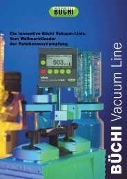
1. Vibration isolator2. Bakeout band3. Inlet-flange seal (supplied)4. <strong>EXT</strong>250Hi pump5. Vent-port6. Solenoid vent-valve7. Vent-port adaptor8. <strong>Manual</strong> vent-valve (supplied)9. Water-cooler (on oppositeside of the pump)10. Purge-port11. Purge-plug (supplied)12. Vent-port adaptor13. Purge restrictor14. Air-cooler15. Inlet-strainer (supplied) *16. Interstage-port *17. Bakeout band position18. Inlet-screen (supplied)* <strong>EXT</strong>250Hi pump onlyFigure 9 - Installation of optional accessories (and spares): <strong>EXT</strong>250Hi shown<strong>EXT</strong> <strong>Compound</strong> <strong>Molecular</strong> <strong>Pumps</strong> 37
7.4.8 ACX air-coolerAn ACX air-cooler can be fitted to the <strong>EXT</strong> pump. However, please refer to Section 3 to check thesuitability of air-cooling in a particular application.Pump Air-cooler Item Number<strong>EXT</strong>70H/Hi ACX70 B580-53-050<strong>EXT</strong>250H/Hi ACX250H B580-53-1607.4.9 Vibration isolatorsIn applications where the small amount of vibration generated by the turbomolecular pump is aproblem, a vibration isolator can be fitted. The isolator consists of two special flanges separatedby a flexible bellows and a rubber, anti-vibration, outer collar. The isolator required depends onthe pump inlet-flange size.Inlet-flange sizeDN63ISO-KDN63CFDN100ISO-KDN100CFItem NumberB581-15-000B581-01-000B581-20-000B581-05-0007.4.10 PRX purge-restrictorThe PRX10 is a modified DN10NW centring-ring which filters the purge gas and restricts itsflow rate to the recommended flow of 25 sccm. The restrictor is suitable for all <strong>EXT</strong> pumps fittedwith a purge-port.Note that you must fit a vent-port adaptor (see Section 7.4.7) to the purge-port on an <strong>EXT</strong>250H or<strong>EXT</strong>250Hi pump, in order to connect the purge restrictor to the pump.Purge-restrictor Flange size Item NumberPRX10 NW10 B580-65-0017.4.11 VRX vent-restrictorUse a VRX fixed orifice vent-restrictor to restrict the flow of vent gas into the <strong>EXT</strong> pump. You canfit a VRX vent-restrictor to the inlet of a TAV5 or TAV6 vent-valve or to a PRX10 purge-restrictor.Refer to Section 3.4 for information on the selection of the correct VRX vent-restrictor.Vent-restrictor Orifice diameter (mm) Item NumberVRX10 0.1 B580-66-021VRX20 0.2 B580-66-022VRX30 0.3 B580-66-023VRX50 0.5 B580-66-024VRX70 0.7 B580-66-02538 <strong>EXT</strong> <strong>Compound</strong> <strong>Molecular</strong> <strong>Pumps</strong>
7.4.12 <strong>EXT</strong>70H/ISO63 interstage-port accessory kitOn the <strong>EXT</strong>70H/ISO63 pump, the interstage-port in the pump-envelope is blanked off. You canremove the blanking cap and fit the interstage-port accessory to upgrade the pump to an<strong>EXT</strong>70Hi pump, so that you can use the interstage-port of the pump as described in Section 3.3.6.The accessory kit consists of an ‘O’ ring and a flange; the flange has an inlet strainer to prevent theentry of debris into the pump. To fit the accessory:Use a suitable pin-spanner to remove the blanking plug from the interstage-port. The holesin the blanking plug are 3.2 mm in diameter, and the centres of the holes are 14 mm apart.Fit the ‘O’ ring supplied, then use a 27 mm diameter ‘C’ spanner to screw the flange into theinterstage-port; the holes in the flange accessory are 3.2 mm in diameter.Tighten the flange sufficiently, to prevent the flange being loosened by vibration or stresstransmitted from pipelines connected to the flange.AccessoryItem Number<strong>EXT</strong>70H/ISO63 interstage-port accessory kitB580-69-001Pin-spannerB279-29-02927 mm ‘C’ spanner B279-29-028<strong>EXT</strong> <strong>Compound</strong> <strong>Molecular</strong> <strong>Pumps</strong> 39
This page intentionally blank.40 <strong>EXT</strong> <strong>Compound</strong> <strong>Molecular</strong> <strong>Pumps</strong>
Return of BOC <strong>Edwards</strong> Equipment - ProcedureForm HS1P900-70-000 Issue KINTRODUCTIONBefore returning your equipment, you must warn BOC <strong>Edwards</strong> if substances you used (and produced)in the equipment can be hazardous. This information is fundamental to the safety of our Service Centreemployees and will determine the procedures employed to service your equipment.Complete the Declaration (HS2) and send it to BOC <strong>Edwards</strong> before you dispatch theequipment. It is important to note that this declaration is for BOC <strong>Edwards</strong> internal use only, andhas no relationship to local, national or international transportation safety or environmentalrequirements. As the person offering the equipment for shipment, it is your responsibility to ensurecompliance with applicable laws.GUIDELINES• Equipment is 'uncontaminated' if it has not been used, or if it has only been used with substancesthat are not hazardous. Your equipment is 'contaminated' if it has been used with any substancesclassified as hazardous under EU Directive 67/548/EEC (as amended) or OSHA Occupational Safety(29 CFR 1910).• If your equipment has been used with radioactive substances, biological or infectious agents,mercury, polychlorinated biphenyls (PCB’s), dioxins or sodium azide, you must decontaminate itbefore you return it to BOC <strong>Edwards</strong>. You must send independent proof of decontamination (forexample a certificate of analysis) to BOC <strong>Edwards</strong> with the Declaration (HS2). Phone BOC<strong>Edwards</strong> for advice.• If your equipment is contaminated, you must either:• Remove all traces of contamination (to the satisfaction of laws governing the transportation ofdangerous/hazardous substances).• Or, properly classify the hazard, mark, manifest and ship the equipment in accordance withapplicable laws governing the shipment of hazardous materials.Note: Some contaminated equipment may not be suitable for airfreight.PROCEDURE1. Contact BOC <strong>Edwards</strong> and obtain a Return Authorisation Number for your equipment.2. Complete the Return of BOC <strong>Edwards</strong> Equipment - Declaration (HS2).3. If the equipment is contaminated, you must contact your transporter to ensure that you properlyclassify the hazard, mark, manifest and ship the equipment, in accordance with applicable lawsgoverning the shipment of contaminated/hazardous materials. As the person offering the equipmentfor shipment, it is your responsibility to ensure compliance with applicable law. Note: Equipmentcontaminated with some hazardous materials, such as semiconductor by-products,may not be suitable for airfreight - contact your transporter for advice.4. Remove all traces of hazardous gases: pass an inert gas through the equipment and any accessoriesthat will be returned to BOC <strong>Edwards</strong>. Where possible, drain all fluids and lubricants from theequipment and its accessories.5. Seal up all of the equipment's inlets and outlets (including those where accessories were attached)with blanking flanges or, for uncontaminated product, with heavy gauge tape.6. Seal equipment in a thick polythene/polyethylene bag or sheet.7. If the equipment is large, strap the equipment and its accessories to a wooden pallet. If theequipment is too small to be strapped to a pallet, pack it in a suitable strong box.8. Fax or post a copy of the Declaration (HS2) to BOC <strong>Edwards</strong>. The Declaration must arrive beforethe equipment.9. Give a copy of the Declaration (HS2) to the transporter. You must tell your transporter if theequipment is contaminated.10. Seal the original Declaration in a suitable envelope: attach the envelope securely to the outside ofthe equipment package, in a clear weatherproof bag.WRITE YOUR RETURN AUTHORISATION NUMBER CLEARLY ON THEOUTSIDE OF THE ENVELOPE OR ON THE OUTSIDE OF THE EQUIPMENTPACKAGE.
Form HS2Return of BOC <strong>Edwards</strong> Equipment - DeclarationReturn Authorisation Number:You must:• Know about all of the substances which have been used and produced in the equipment before you complete this Declaration• Read the Return of BOC <strong>Edwards</strong> Equipment - Procedure (HS1) before you complete this Declaration• Contact BOC <strong>Edwards</strong> to obtain a Return Authorisation Number and to obtain advice if you have any questions• Send this form to BOC <strong>Edwards</strong> before you return your equipmentEquipment/System Name_________________________Part Number _________________________________Serial Number_________________________________Has the equipment been used, tested or operated ?YES R Go to Section 2 NO R Go to Section 4IF APPLICABLE:Tool Reference Number_________________Process ______________________________Failure Date___________________________Serial Number ofReplacement Equipment_________________SECTION 2: SUBSTANCES IN CONTACT WITH THE EQUIPMENTAre any substances used or produced in the equipment:• Radioactive, biological or infectious agents, mercury,poly chlorinated biphenyls (PCBs), dioxinsor sodium azide? (if YES, see Note 1) YES R NO R• Hazardous to humanhealth and safety?SECTION 1: EQUIPMENTYES R NO RNote 1 : BOC <strong>Edwards</strong> will not accept delivery of anyequipment that is contaminated with radioactive substances,biological/infectious agents, mercury, PCB’s, dioxins orsodium azide, unless you:• Decontaminate the equipment• Provide proof of decontaminationYOU MUST CONTACT BOC EDWARDS FOR ADVICEBEFORE YOU RETURN SUCH EQUIPMENTSECTION 3: LIST OF SUBSTANCES IN CONTACT WITH THE EQUIPMENTSubstance nameChemicalSymbolPrecautions required (for example,use protective gloves, etc.)Action required after a spill,leak or exposureSECTION 4: RETURN INFORMATIONReason for return and symptoms of malfunction __________________________________________________________________________________________________________________________________If you have a warranty claim:• who did you buy the equipment from ? _____________________________• give the supplier’s invoice number_________________________________SECTION 5: DECLARATIONPrint your name:_________________________________Print your job title:_________________________Print your organisation:____________________________________________________________________Print your address:______________________________________________________________________________________________________________________________________________Telephone number: ___________________________Date of equipment delivery: ______________I have made reasonable enquiry and I have supplied accurate information in thisDeclaration. I have not withheld any information, and I have followed the Return ofBOC <strong>Edwards</strong> Equipment - Procedure (HS1).Signed: _____________________________________Date______________Note: Please print out thisform, sign it and return thesigned form as hard copy.P900-71-000 Issue K
This page intentionally blank.
P800-80-000 Issue J 01A09-010UNITED KINGDOMCORPORATE HEADQUARTERSBOC EDWARDSManor RoyalCrawleyWest SussexRH10 9LWTel +(44) 1293 528844Fax +(44) 1293 533453BOC EDWARDSWingates Industrial EstateGreat Bank RoadWesthoughton, BoltonLancashireBL5 3SLTel +(44) 1942 652652Fax +(44) 1942 652651AMERICA (USA)USA HEADQUARTERSBOC EDWARDSOne <strong>Edwards</strong> Park301 Ballardvale StreetWilmington, MA 01887Tel +(1) 978 658 5410Toll free (USA only) 1 800 848 9800Fax +(1) 978 658 79693901 Burton DriveSanta Clara, CA 95054Tel +(1) 408 496 1177Fax +(1) 408 496 11881810 West Drake DriveSuite 101Tempe, AZ 85283Tel +(1) 602 777 7007Fax +(1) 602 777 224411701 Stonehollow DriveSuite 100Austin, TX 78758Tel +(1) 512 491 6622Fax +(1) 512 491 06293501 Island AvenuePhiladelphia, PA 19153Tel +(1) 215 365 8653Fax +(1) 978 753 6846BELGIUMBOC EDWARDSBergensesteenweg 709B1600 Sint-Pieters-LeeuwBrusselsTel +(32) 2 363 0030Fax +(32) 2 363 0064BRAZILBOC DO BRASIL LTDADIVISÃO EDWARDS ALTO VACORua Bernado Wrona 22202710 São Paulo-SPTel +(55) 11 3952 5000Fax +(55) 11 3965 2766CANADABOC EDWARDS5975 Falbourne StreetMississauga, Ontario L5R3W6CanadaTel +(1) 905 501 2558Fax +(1) 905 501 163212055 Cote de LiesseDorval, Quebec H9P1B4CanadaTel +(1) 514 631 3501Fax +(1) 514 631 3502CHINABOC TRADING(SHANGHAI) CO. LTD.23 Fu Te Road (N)Wai Gao Qiao Free Trade ZonePudongShanghai, 200131PRC ChinaTel +(86 21) 5866 9618Fax +(86 21) 5866 9993FRANCEBOC EDWARDS125 Avenue Louis Roche92238 Gennevilliers, CedexParisTel +(33) 1 47 98 24 01Fax +(33) 1 47 98 44 54GERMANYBOC EDWARDSAmmerthalstraße 3685551 KirchheimMunichTel +(49) 89 99 19 18 0Fax +(49) 89 99 19 18 99HONG KONG S.A.R.BOC EDWARDS (ASIA)12 Chun Yat StreetTseung Kwan O Industrial EstateTseung Kwan O, KowloonHong Kong S.A.R.Tel +(852) 2372 2640Fax +(852) 2796 9095INDIABOC EDWARDSDIVIN. OF BOC INDIA LIMITED203 Surya Kiran Building19 Kasturba Gandhi MargNew Delhi - 110 001IndiaTel +(91) 11 851 0065Fax +(91) 11 851 0245ISRAELEDWARDS ISRAEL VACUUM LTD.5 Habarzel BlvdGat 2000 Industrial ZoneQiryat Gat 82000Tel +(972) 8 681 0633Fax +(972) 8 681 0640ITALYBOC EDWARDSVia Carpaccio 3520090 Trezzano sul NaviglioMilanTel +(39) 02 48 4471Fax +(39) 02 48 401638JAPANHEADQUARTERSBOC EDWARDSShuwa Shiba Park Building A-3F2-4-1 Shibakoen Minato-kuTokyo, 105-0011Tel +(81) (0) 3 5470 6530Fax +(81) (0) 3 5470 6521KOREAHEADQUARTERSSONGWON EDWARDS LTD.5th FL. Daewoo Engineering Bldg.Soonae-dongBundang-gu, Sungnam CityKyungki-do, KoreaTel +(82) 31 716 7070Fax +(82) 31 738 1001-3FACTORY & GVSONGWON EDWARDS LTD.625-7 Upsong-dongChunan CityChungchong Nam-doKoreaTel +(82) 41 621 7070Fax +(82) 41 621 7700SINGAPOREBOC EDWARDS (ASIA)42 Loyang DriveLoyang Industrial EstateSingapore 508962Tel +(65) 6546 8408Fax +(65) 6546 8407TAIWAN, R.O.C.EDWARDS TECHNOLOGIESLIMITEDNo. 434 Chung hua RoadToufen Town, Miaoli CountyTaiwan ROCTel +(886) 37 611422Fax +(886) 37 611401PLEASE CONTACT ANY OF THESE COMPANIES FOR DETAILS OF OTHER SALES ANDSERVICE CENTRES IN YOUR AREA.BOC <strong>Edwards</strong> is part of BOC Limited. BOC <strong>Edwards</strong> and the stripe symbol are trade marks of The BOC Group.© BOC <strong>Edwards</strong> 2003Produced by Technical Publicity Techpublicity@edwards.boc.comhttp://www.bocedwards.cominfo@bocedwards.com