Rolls-Royce Remote Oil Filler Valve Bulletin - Code7700
Rolls-Royce Remote Oil Filler Valve Bulletin - Code7700
Rolls-Royce Remote Oil Filler Valve Bulletin - Code7700

You also want an ePaper? Increase the reach of your titles
YUMPU automatically turns print PDFs into web optimized ePapers that Google loves.
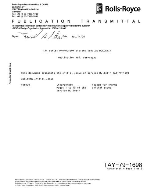
Jul.14/06TAY SERIES PROPULSION SYSTEMS SERVICE BULLETINPublication Ref. Ser-TayACPrinted in Great BritainThis document transmits the Initial Issue of Service <strong>Bulletin</strong> TAY-79-1698<strong>Bulletin</strong> Initial IssueRemove Incorporate Reason for changePages 1 to 15 of the Initial IssueService <strong>Bulletin</strong>TAY−79−1698Transmittal - Page 1 of 2
LIST OF EFFECTIVE PAGESThe effective pages to this Service <strong>Bulletin</strong> are as follows:Page Revision Number Revision Date<strong>Bulletin</strong>1 Jul.14/062 Jul.14/063 Jul.14/064 Jul.14/065 Jul.14/066 Jul.14/067 Jul.14/068 Jul.14/069 Jul.14/0610 Jul.14/0611 Jul.14/0612 Jul.14/0613 Jul.14/0614 Jul.14/0615 Jul.14/06Printed in Great BritainTAY−79−1698Transmittal - Page 2
OIL - REMOTE OIL FILL VALVE - INTRODUCTION OF A NEW REMOTE OIL FILL VALVE (ROFV) WITHA MODIFIED PISTON AND VALVE SEAT - MOD.79-16981. Planning InformationPrinted in Great BritainA. Effectivity(1) Gulfstream IV-X.Tay 611-8C Engines, prior to Engine Serial Number 85120.Non-Modular.B. Concurrent RequirementsNone.C. Reason(1) Problem<strong>Oil</strong> leakage from the <strong>Remote</strong> <strong>Oil</strong> Fill <strong>Valve</strong> (ROFV) overflow port can occurafter oil filling operation. The oil leakage is caused by the valve notclosing fast enough after the oil filling operation, because of acondition known as 'hydraulic lock'. The overflow passage then staysslightly open and the accessory gearbox internal air pressure thatdevelops during engine operation causes the oil to be pushed out of theROFV overflow port to overboard.(2) EvidenceThis was identified on engines in service.(3) SubstantiationThe changes introduced by this Service <strong>Bulletin</strong> were the subject ofsatisfactory engineering analysis and tests. This Service <strong>Bulletin</strong>complies with the applicable engine certification basis.(4) ObjectiveIntroduction of this Service <strong>Bulletin</strong> is designed to maintain reliability.Jul.14/06Jul.14/06TAY−79−1698Page 1 of 15
(5) Effect of <strong>Bulletin</strong> on:(a) OperationNot affected.(b) MaintenanceNot affected.(c) OverhaulNot affected.Printed in Great BritainD. Description(d) Repair SchemesNot affected.(e) InterchangeabilityNot affected.(f) Fits and ClearancesNot affected.This Service <strong>Bulletin</strong> introduces a new ROFV with improved sealing of the inletcheck valve and the overfill valve.The changes are as follows:(1) The skirt length of the valve piston is decreased without changes to thepiston overall length. This makes sure that the fill port to the oil tankis never completely blocked (i.e. no 'hydraulic lock' possible).(2) The overfill valve outside diameter is decreased from between 24,64 and25,15 mm (0.970 and 0.990 in.) to between 24,64 and 24,77 mm (0.970 and0.975 in.). This makes sure that there is adequate clearance between theoverfill valve outside diameter and the counterbore inside diameter.(3) A new main bore machining process is introduced to give an improvedsurface finish.Jul.14/06Jul.14/06TAY−79−1698Page 2
I. Tooling Price and AvailabilityNew tools are not required.J. Industry Support InformationNone.K. Weight and Balance(1) Weight ChangeNone.Printed in Great Britain(2) Moment ArmNo effect.(3) DatumES2540 (PPS100).L. Electrical Load DataThe aircraft electrical load is not affected by this Service <strong>Bulletin</strong>.M. Software Accomplishment SummaryNot applicable.N. References(1) Modification <strong>Bulletin</strong> 79-1698 Issue 01 dated Jul.10/06.(2) Aircraft Maintenance Manual, Chapters 12-14-79, 70-00-06, 70-10-02,70-20-01, 70-50-02, 71-00-00, 71-10-00 and 79-10-00.(3) Engine Manual - E-TAY-6RR, Chapter 72-00-00.(4) Standard Practices Manual - RR-CAEL-SPM, Chapters 70-02-01, 70-12-04,70-21-00 and 70-51-00.(5) Overhaul Materials Manual - OMat, Section 2.O. Other Publications Affected(1) Illustrated Parts Catalog - S-TAY6118C-6RR, Chapter 79-11-01.P. Interchangeability of PartsNot affected.Jul.14/06Jul.14/06TAY−79−1698Page 4
2. Material InformationA. Parts required to accomplish this Service <strong>Bulletin</strong> (In addition to Parts in2.B., 2.C. and 2.E.)Printed in Great BritainIPCFig/ItemNo.79-11-01NewPartNo.Unit Price(USDollars)QtyPerEng.Key Word03-100 237-0263-03 P.O.A. 1 <strong>Remote</strong> <strong>Oil</strong> Fill<strong>Valve</strong> (ROFV)OldPartNo.Instructions/Dispositions237-0263-02 (1)B. Parts to be ReworkedNone.C. New Production PartsNone.D. Redundant PartsNone.E. Expendable PartsIPCFig/ItemNo.NewPartNo.Unit Price(USDollars)QtyPerEng.Key WordOldPartNo.Instructions/Dispositions79-11-0103-095 AS43013-218 P.O.A. 1 Seal ring AS43013-218 (2)Refer also to the related Manual tasks given in the Accomplishment Instructionof this Service <strong>Bulletin</strong>.F. Instruction/Disposition Codes(1) The old and new parts are interchangeable, but once the new part has beeninstalled it is recommended not to re-install the old part.(2) It is necessary to replace the used part with a new part during theaccomplishment of this Service <strong>Bulletin</strong>.Jul.14/06Jul.14/06TAY−79−1698Page 5
3. Accomplishment InstructionPART 1 - APPLICABLE FOR ENGINES 'IN SERVICE'A. GeneralNOTE:WARNING:WARNING:WARNING:WARNING:WARNING:CAUTION:CAUTION:In order to reduce the potential for multiple-engine in-flight shutdown,power loss, or other anomaly due to maintenance error, <strong>Rolls</strong>-<strong>Royce</strong>Deutschland recommends that Operators avoid performing maintenance onmultiple engines installed on the same aircraft at the same time. If itis not possible to avoid maintenance on more than one engine at the sametime, <strong>Rolls</strong>-<strong>Royce</strong> Deutschland recommends that additional controls areapplied in order to ensure that maintenance tasks have been completed asdefined.YOU MUST BE CAREFUL WHEN YOU WORK ON THE ENGINE COMPONENTS AFTER THEENGINE IS STOPPED. THE ENGINE COMPONENTS CAN STAY HOT FOR ALMOST ONEHOUR.YOU MUST NOT TOUCH HOT PARTS WITHOUT APPLICABLE GLOVES. HOT PARTS CANCAUSE AN INJURY. IF YOU GET AN INJURY PUT IT IN COLD WATER FOR 10MINUTES AND GET MEDICAL AID.YOU MUST USE EYE PROTECTION WHEN YOU CUT SAFETY CABLE OR LOCKWIRE. IFYOU DO NOT OBEY THIS INSTRUCTION, PIECES OF SAFETY CABLE OR LOCKWIRE CANHIT YOUR EYES AND CAUSE AN INJURY.DO NOT LET USED SAFETY CABLE OR USED LOCKWIRE STAY ON OR NEAR THEENGINE. USED SAFETY CABLE OR USED LOCKWIRE MUST BE DISCARDED IN THECORRECT CONTAINER. IF YOU DO NOT OBEY THIS INSTRUCTION INJURY TO PERSONSAND/OR DAMAGE TO THE ENGINE CAN OCCUR.DO NOT LET ENGINE OIL STAY ON YOUR SKIN. REMOVE THE ENGINE OIL FROM YOURSKIN WITH SOAP AND WATER. THE ENGINE OIL IS POISONOUS AND CAN BEABSORBED INTO YOUR BODY.YOU MUST NOT LET ENGINE OIL FALL ON THE ENGINE. UNWANTED OIL MUST BEREMOVED IMMEDIATELY WITH A CLEAN LINT-FREE CLOTH. THE OIL CAN CAUSEDAMAGE TO THE SURFACE PROTECTION AND SOME PARTS.YOU MUST NOT PUT OIL THAT HAS BEEN DRAINED FROM THE ENGINE BACK INTO THEOIL SYSTEM. CONTAMINATION IN THE OIL CAN CAUSE DAMAGE TO THE ENGINE.Printed in Great Britain(1) Obey all the WARNINGS and CAUTIONS in the procedures that are referred to.Jul.14/06Jul.14/06TAY−79−1698Page 6
(2) Consumable Materials(a) Refer to the table that follows:Printed in Great BritainOMAT NO.238 Lockwire2/142 Safety CableDESIGNATIONFor the details of the consumable materials given in the table aboverefer to the Overhaul Materials Manual.(b) For further consumable materials refer also to the related Manualtasks given in this instruction.(3) Tools and Equipment(a) Refer to the table that follows:REFERENCENo SpecificNo SpecificDESIGNATIONContainer (Fuel and <strong>Oil</strong> Resistant)Protective Covers, Blanks or Caps(b) For further tools and equipment refer also to the related Manual tasksgiven in this instruction.(4) Refer to the Aircraft Maintenance Manual, Chapter 70-00-06, PB201 for theidentification, lubrication and installation of flexible seal rings.(5) Refer to the Aircraft Maintenance Manual, Chapter 70-10-02, PB201 for thelocking techniques for threaded parts.(6) Refer to the Aircraft Maintenance Manual, Chapter 70-20-01, PB201 for theprocedure to clean engine parts.(7) Refer to the Aircraft Maintenance Manual, Chapter 70-50-02, PB201 for alltorque procedures.B. Get access to the <strong>Remote</strong> <strong>Oil</strong> Fill <strong>Valve</strong> (ROFV) that is installed on the rearface of the oil tank(1) Open the applicable cowl doors (Refer to the Aircraft Maintenance Manual,Chapter 71-10-00, PB201).C. Make sure that the remote oil fill system on aircraft side is isolated.D. Drain the engine oil from the oil tank (Refer to the Aircraft MaintenanceManual, Chapter 79-10-00, PB301).Jul.14/06Jul.14/06TAY−79−1698Page 7
E. Remove the breather tube (79-11-01, 03-170) that is installed between the oiltank emergency fill adapter (79-11-01, 03-180) and the ROFV (79-11-01, 03-100)(Refer to Figure 1)(1) Cut and remove the safety cable or the lockwire from the two union nuts(1) and (2) of the breather tube (79-11-01, 03-170).(2) Disconnect the union nut (1) that attaches the breather tube (79-11-01,03-170) to the ROFV (79-11-01, 03-100).(3) Disconnect the union nut (2) that attaches the breather tube (79-11-01,03-170) to the oil tank emergency fill adapter (79-11-01, 03-180).(4) Remove the breather tube (79-11-01, 03-170) from the engine.Printed in Great Britain(5) Install protective covers, blanks or caps on the openings of the breathertube (79-11-01, 03-170) and the oil tank emergency fill adapter (79-11-01,03-180).F. Remove the old ROFV (79-11-01, 03-100), P/N 237-0263-02 that is installed onthe mounting adapter at the rear face of the oil tank (Refer to Figure 1)(1) Put a clean oil resistant container in position below the ROFV (79-11-01,03-100) to catch the drained oil.(2) Disconnect the union nut (3) that attaches the pressure fill tube (4) tothe ROFV (79-11-01, 03-100).(3) Disconnect the union nut (5) that attaches the overflow tube (6) to theROFV (79-11-01, 03-100).(4) Remove the four bolts (79-11-01, 03-102) and the four washers (79-11-01,03-104) that attach the ROFV (79-11-01, 03-100) to the mounting adapter.(5) Remove the old ROFV (79-11-01, 03-100), P/N 237-0263-02 together with theused seal ring (79-11-01, 03-095), P/N AS43013-218 from the mountingadapter.(6) Move the container with the drained oil away from the engine and discardthe drained oil.Jul.14/06Jul.14/06TAY−79−1698Page 8
G. Install the new ROFV (79-11-01, 03-100), P/N 237-0263-03 on the mountingadapter at the rear face of the oil tank (Refer to Figure 1)(1) Remove all protective covers, blanks or caps from the ROFV (79-11-01,03-100).Printed in Great Britain(2) Clean the mating surfaces of the ROFV (79-11-01, 03-100) and the mountingadapter.(3) Lubricate and install a new seal ring (79-11-01, 03-095), P/N AS43013-218on the ROFV (79-11-01, 03-100).(4) Put and hold the new ROFV (79-11-01, 03-100), P/N 237-0263-03 in positionon the mounting adapter.(5) Install the four bolts (79-11-01, 03-102) and the four washers (79-11-01,03-104) that attach the ROFV (79-11-01, 03-100) to the mounting adapter.(6) Torque the four bolts (79-11-01, 03-102) to 11,5 Nm (100 lbf in.).(7) Install the union nut (3) that attaches the pressure fill tube (4) to theROFV (79-11-01, 03-100).(8) Torque the union nut (3) of the pressure fill tube (4) to between 35,6 and39 Nm (315 and 345 lbf in.).(9) Install the union nut (5) that attaches the overflow tube (6) to the ROFV(79-11-01, 03-100).(10) Torque the union nut (5) of the overflow tube (6) to between 53,1 and 58,7Nm (470 and 520 lbf in.).H. Install the breather tube (79-11-01, 03-170) between the oil tank emergencyfill adapter (79-11-01, 03-180) and the ROFV (79-11-01, 03-100) (Refer toFigure 1)(1) Remove all protective covers, blanks or caps from the breather tube(79-11-01, 03-170) and the oil tank emergency fill adapter (79-11-01,03-180).(2) Put and hold the breather tube (79-11-01, 03-170) in position between theoil tank emergency fill adapter (79-11-01, 03-180) and the ROFV (79-11-01,03-100)(a) The breather tube (79-11-01, 03-170) is identified with the twomarkings 'TANK' and 'VALVE' on its outer skin. Install the end of thebreather tube (79-11-01, 03-170) identified with the marking 'TANK' onthe oil tank emergency fill adapter (79-11-01, 03-180). Install theother end of the breather tube (79-11-01, 03-170) identified with themarking 'VALVE' on the ROFV (79-11-01, 03-100).Jul.14/06Jul.14/06TAY−79−1698Page 9
(3) Loosely install the union nut (2) that attaches the breather tube(79-11-01, 03-170) to the oil tank emergency fill adapter (79-11-01,03-180).(4) Loosely install the union nut (1) that attaches the breather tube(79-11-01, 03-170) to the ROFV (79-11-01, 03-100).(5) Torque the two union nuts (1) and (2) of the breather tube (79-11-01,03-170) to 19 Nm (170 lbf in.).(6) Safety the two union nuts (1) and (2) of the breather tube (79-11-01,03-170) with safety cable (OMat 2/142) or with lockwire (OMat 238).NOTE:Safety cable (OMat 2/142) is the preferred locking material.Printed in Great BritainI. Replenish the oil tank with engine oil (Refer to the Aircraft MaintenanceManual, Chapter 12-14-79, PB301).J. Make sure that the remote oil fill system on aircraft side is activated.K. Make sure that the work area is clean and clear of tools, equipment and otherunwanted materials.L. Do an engine run leak check (Test 2) (Refer to the Aircraft Maintenance Manual,Chapter 71-00-00, PB501).M. Close the access to the ROFV(1) Close the cowl doors (Refer to the Aircraft Maintenance Manual, Chapter71-10-00, PB201).N. A record of accomplishment is required. <strong>Rolls</strong>-<strong>Royce</strong> Deutschland suggests to putan entry into the engine log book.Jul.14/06Jul.14/06TAY−79−1698Page 10
PART 2 - APPLICABLE FOR ENGINES 'AT OVERHAUL/SHOP VISIT'O. GeneralPrinted in Great BritainWARNING:WARNING:WARNING:CAUTION:CAUTION:YOU MUST USE EYE PROTECTION WHEN YOU CUT SAFETY CABLE OR LOCKWIRE. IFYOU DO NOT OBEY THIS INSTRUCTION, PIECES OF SAFETY CABLE OR LOCKWIRE CANHIT YOUR EYES AND CAUSE AN INJURY.DO NOT LET USED SAFETY CABLE OR USED LOCKWIRE STAY ON OR NEAR THEENGINE. USED SAFETY CABLE OR USED LOCKWIRE MUST BE DISCARDED IN THECORRECT CONTAINER. IF YOU DO NOT OBEY THIS INSTRUCTION INJURY TO PERSONSAND/OR DAMAGE TO THE ENGINE CAN OCCUR.DO NOT LET ENGINE OIL STAY ON YOUR SKIN. REMOVE THE ENGINE OIL FROM YOURSKIN WITH SOAP AND WATER. THE ENGINE OIL IS POISONOUS AND CAN BEABSORBED INTO YOUR BODY.YOU MUST NOT LET ENGINE OIL FALL ON THE ENGINE. UNWANTED OIL MUST BEREMOVED IMMEDIATELY WITH A CLEAN LINT-FREE CLOTH. THE OIL CAN CAUSEDAMAGE TO THE SURFACE PROTECTION AND SOME PARTS.YOU MUST NOT PUT OIL THAT HAS BEEN DRAINED FROM THE ENGINE BACK INTO THEOIL SYSTEM. CONTAMINATION IN THE OIL CAN CAUSE DAMAGE TO THE ENGINE.(1) Obey all the WARNINGS and CAUTIONS in the procedures that are referred to.(2) Consumable Materials(a) Refer to the table that follows:OMAT NO.238 Lockwire2/142 Safety CableDESIGNATIONFor the details of the consumable materials given in the table aboverefer to the Overhaul Materials Manual.(b) For further consumable materials refer also to the related Manualtasks given in this instruction.(3) Tools and Equipment(a) Refer to the table that follows:REFERENCENo SpecificNo SpecificDESIGNATIONContainer (Fuel and <strong>Oil</strong> Resistant)Protective Covers, Blanks or Caps(b) For further tools and equipment refer also to the related Manual tasksgiven in this instruction.Jul.14/06Jul.14/06TAY−79−1698Page 11
(4) Refer to the Standard Practices Manual, Chapter 70-02-01, TASK70-02-01-400-000 for the identification, lubrication and installation offlexible seal rings.(5) Refer to the Standard Practices Manual, Chapter 70-12-04, TASK70-12-04-400-000 for the locking techniques for threaded parts.(6) Refer to the Standard Practices Manual, Chapter 70-21-00, TASK70-21-00-100-000 for the procedure to clean engine parts.(7) Refer to the Standard Practices Manual, Chapter 70-51-00, TASK70-51-00-400-000 for all torque procedures.P. Get access to the <strong>Remote</strong> <strong>Oil</strong> Fill <strong>Valve</strong> (ROFV) that is installed on the rearface of the oil tank.Printed in Great BritainQ. Drain the engine oil from the oil tank (Refer to the Engine Manual, Chapter72-00-00, TASK 72-00-00-600-802).R. Remove the breather tube (79-11-01, 03-170) that is installed between the oiltank emergency fill adapter (79-11-01, 03-180) and the ROFV (79-11-01, 03-100)(Refer to Figure 1)(1) Cut and remove the safety cable or the lockwire from the two union nuts(1) and (2) of the breather tube (79-11-01, 03-170).(2) Disconnect the union nut (1) that attaches the breather tube (79-11-01,03-170) to the ROFV (79-11-01, 03-100).(3) Disconnect the union nut (2) that attaches the breather tube (79-11-01,03-170) to the oil tank emergency fill adapter (79-11-01, 03-180).(4) Remove the breather tube (79-11-01, 03-170) from the engine.(5) Install protective covers, blanks or caps on the openings of the breathertube (79-11-01, 03-170) and the oil tank emergency fill adapter (79-11-01,03-180).Jul.14/06Jul.14/06TAY−79−1698Page 12
S. Remove the old ROFV (79-11-01, 03-100), P/N 237-0263-02 that is installed onthe mounting adapter at the rear face of the oil tank (Refer to Figure 1)(1) Put a clean oil resistant container in position below the ROFV (79-11-01,03-100) to catch the drained oil.Printed in Great Britain(2) Remove the four bolts (79-11-01, 03-102) and the four washers (79-11-01,03-104) that attach the ROFV (79-11-01, 03-100) to the mounting adapter.(3) Remove the old ROFV (79-11-01, 03-100), P/N 237-0263-02 together with theused seal ring (79-11-01, 03-095), P/N AS43013-218 from the mountingadapter.(4) Move the container with the drained oil away from the engine and discardthe drained oil.T. Install the new ROFV (79-11-01, 03-100), P/N 237-0263-03 on the mountingadapter at the rear face of the oil tank (Refer to Figure 1)(1) Remove the applicable covers, blanks or caps from the ROFV (79-11-01,03-100).(2) Clean the mating surfaces of the ROFV (79-11-01, 03-100) and the mountingadapter.(3) Lubricate and install a new seal ring (79-11-01, 03-095), P/N AS43013-218on the ROFV (79-11-01, 03-100).(4) Put and hold the new ROFV (79-11-01, 03-100), P/N 237-0263-03 in positionon the mounting adapter.(5) Install the four bolts (79-11-01, 03-102) and the four washers (79-11-01,03-104) that attach the ROFV (79-11-01, 03-100) to the mounting adapter.(6) Torque the four bolts (79-11-01, 03-102) to 11,5 Nm (100 lbf in.).Jul.14/06Jul.14/06TAY−79−1698Page 13
U. Install the breather tube (79-11-01, 03-170) between the oil tank emergencyfill adapter (79-11-01, 03-180) and the ROFV (79-11-01, 03-100) (Refer toFigure 1)(1) Remove all protective covers, blanks or caps from the breather tube(79-11-01, 03-170) and the oil tank emergency fill adapter (79-11-01,03-180).(2) Put and hold the breather tube (79-11-01, 03-170) in position between theoil tank emergency fill adapter (79-11-01, 03-180) and the ROFV (79-11-01,03-100)(a) The breather tube (79-11-01, 03-170) is identified with the twomarkings 'TANK' and 'VALVE' on its outer skin. Install the end of thebreather tube (79-11-01, 03-170) identified with the marking 'TANK' onthe oil tank emergency fill adapter (79-11-01, 03-180). Install theother end of the breather tube (79-11-01, 03-170) identified with themarking 'VALVE' on the ROFV (79-11-01, 03-100).Printed in Great Britain(3) Loosely install the union nut (2) that attaches the breather tube(79-11-01, 03-170) to the oil tank emergency fill adapter (79-11-01,03-180).(4) Loosely install the union nut (1) that attaches the breather tube(79-11-01, 03-170) to the ROFV (79-11-01, 03-100).(5) Torque the two union nuts (1) and (2) of the breather tube (79-11-01,03-170) to 19 Nm (170 lbf in.).(6) Safety the two union nuts (1) and (2) of the breather tube (79-11-01,03-170) with safety cable (OMat 2/142) or with lockwire (OMat 238).NOTE:Safety cable (OMat 2/142) is the preferred locking material.V. Replenish the oil tank with engine oil (Refer to the Engine Manual, Chapter72-00-00, TASK 72-00-00-600-803).W. Make sure that the work area is clean and clear of tools, equipment and otherunwanted materials.X. A record of accomplishment is required. <strong>Rolls</strong>-<strong>Royce</strong> Deutschland suggests to putan entry into the engine log book.Jul.14/06Jul.14/06TAY−79−1698Page 14
Printed in Great BritainRemoval and Installation of the <strong>Remote</strong> <strong>Oil</strong> Fill <strong>Valve</strong> (ROFV) (79-11-01, 03-100)Figure 1Jul.14/06Jul.14/06TAY−79−1698Page 15