UNIVERSITI TEKNOLOGI MALAYSIA - FKE - UTM
UNIVERSITI TEKNOLOGI MALAYSIA - FKE - UTM
UNIVERSITI TEKNOLOGI MALAYSIA - FKE - UTM

You also want an ePaper? Increase the reach of your titles
YUMPU automatically turns print PDFs into web optimized ePapers that Google loves.
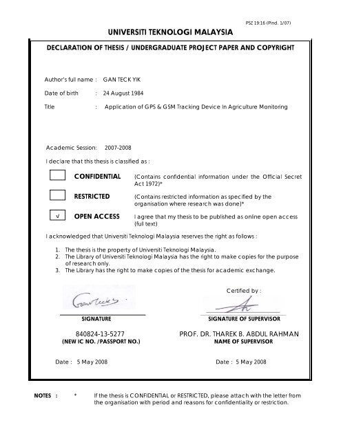
<strong>UNIVERSITI</strong> <strong>TEKNOLOGI</strong> <strong>MALAYSIA</strong>PSZ 19:16 (Pind. 1/07)DECLARATION OF THESIS / UNDERGRADUATE PROJECT PAPER AND COPYRIGHTAuthor’s full name :GAN TECK YIKDate of birth : 24 August 1984Title : Application of GPS & GSM Tracking Device In Agriculture MonitoringAcademic Session : 2007-2008I declare that this thesis is classified as :√CONFIDENTIALRESTRICTEDOPEN ACCESS(Contains confidential information under the Official SecretAct 1972)*(Contains restricted information as specified by theorganisation where research was done)*I agree that my thesis to be published as online open access(full text)I acknowledged that Universiti Teknologi Malaysia reserves the right as follows :1. The thesis is the property of Universiti Teknologi Malaysia.2. The Library of Universiti Teknologi Malaysia has the right to make copies for the purposeof research only.3. The Library has the right to make copies of the thesis for academic exchange.Certified by :SIGNATURESIGNATURE OF SUPERVISOR840824-13-5277 PROF. DR. THAREK B. ABDUL RAHMAN(NEW IC NO. /PASSPORT NO.)NAME OF SUPERVISORDate : 5 May 2008 Date : 5 May 2008NOTES : * If the thesis is CONFIDENTIAL or RESTRICTED, please attach with the letter fromthe organisation with period and reasons for confidentiality or restriction.
APPLICATION OF GPS & GSM TRACKING DEVICE IN AGRICULTUREMONITORINGGAN TECK YIK<strong>UNIVERSITI</strong> <strong>TEKNOLOGI</strong> <strong>MALAYSIA</strong>
“I hereby declare that I have read this thesis and in my opinion this thesis issufficient in terms of scope and quality for the award of the degree of Electrical-Telecommunication Engineering”Signature: ……………………………..Name of Supervisor : PROF. DR. THAREK B. ABDUL RAHMANDate : 5 MAY 2008
iiAPPLICATION OF GSP & GSM TRACKING DEVICE INAGRICULTURE MONITORINGGAN TECK YIKThis report is submitted in fulfillment for the Bachelor Degree in Electrical –Telecommunication EngineeringFaculty of Electrical EngineeringUniversity Technology MalaysiaMAY, 2008
iii“I hereby declare that the thesis entitled “Application of GSP & GSM TrackingDevice in Agriculture Monitoring” is the result of my own effort except as cited inthe reference. The thesis has not been accepted for any degree and is notconcurrently in candidature of any degree.”Signature : ………………………………….Author : GAN TECK YIKDate : 5 May 2008
Specially dedicated to my beloved parents and friends for their unconditionalsupport and encouragement.iv
vACKNOWLEDGEMENTFirstly, I would like to take this opportunity to express my greatestgratitude to my project supervisor, Prof. Dr. Tharek bin Abdul Rahman for hisguidance and encouragement throughout the 2 semester. Without his never endingsupport and interest, this thesis would not have the same as presented here.I would like to thank my co-supervisor Mr. Chua Tien Han and Mr. LeowChee Yen for their valuable assistant and opinions about this project.Also I would like to thank the System Development Manager of BSmartTechnology Sdn. Bhd., Mr. Freddy Tan for helping and providing training to mefor this project. Without his generous help, this project would not be successfulcompleted.I wish to extend special thanks to all <strong>UTM</strong> lecturers who have beenteaching me since first year, course mates and friends who have assist me directlyand indirectly in this project.Last but not least, to my beloved family who has always been there toencourage, comfort and give their fullest support when I most needed them.
viABSTRACTFarmers nowadays are constantly searching for ways to maximize theirreturns and profits. Hence, in order to achieve that, farmers need to monitor theirplants. This project mainly looks on how a device (b’AT) which consists of a GPSreceiver and a GSM modem can be used to monitor the plants. In other words, asystem is created under the b’AT platform so that it can be used to monitor plants.This project emphasizes on writing the source code using C language so that theb’AT unit can receive information from the GPS satellites and the sensors. Afterthat, the information will be send to the backend server using SMS format to bestored. The information will be display out also in a web database where thefarmers can access anywhere so that the farmers can monitor. Besides that, theapplication of GSM modem enables the farmers to send SMS to the b’AT toacquire latest situation of their plants. During critical situation, the b’AT also cansend SMS to the farmers as a warning.
viiABSTRAKPetani pada zaman ini sentiasa mencari cara-cara untuk memaksimumkanhasil dan pendapatan pertanian mereka. Oleh itu, untuk mancapai matlamattersebut, para petani mesti memantau tanaman mereka. Projek ini menitik beratkanbagaimana mengunakan satu alat (b’AT) yang mengandungi satu penerima GPSdan satu modem GSM untuk membuat pamantauan tanaman. Dalam lain kata, satusystem perlu dicipta mengunakan b’AT tersebut bagi tujuan pemantauan tanaman.Projek ini juga menitik beratkan penulisan kod sumber menggunakan bahasa Csupaya b’AT tersebut boleh menerima maklumat dari satelit GPS dan pengesan.Selepas itu, semua maklumat tersebut akan dihantar ke satu server menggunakanformat SMS untuk disimpan. Maklumat tersebut akan dipaparkan di suatu webdatabase supaya para petani boleh membuat pamantauan. Selain itu, denganadanya modem GSM tersebut, para petani boleh menghantar pasanan SMS kapadab’AT tersebut untuk mendapatkan situasi terkini tentang tanaman mereka. Semasawaktu kecemasan, sistem tersebut juga boleh menghantar SMS amaran kepadapara petani untuk memberi amaran kepada mereka.
viiiTABLE OF CONTENTSCHAPTER TITLE PAGETITLE PAGEDECLARATIONDEDICATIONACKNOWLEDGEMENTABSTRACTABSTRAKTABLE OF CONTENTSLIST OF TABLELIST OF FIGURESivvviviiviiixixiixiiiCHAPTER 1INTRODUCTION1.1 Project Background 11.2 Problem Statement 21.3 Objectives 31.4 Scopes 41.5 Planning 4CHAPTER 2LITERATURE REVIEW2.1 Introduction 62.2 Electronic Agriculture Monitoring 6
ix2.3 The GPS System 82.3.1 GPS Receiver 92.4 The GSM System 102.4.1 GPRS 122.5 Short Messaging Service 132.6 Concurrent GPS and GSM Real 14Time Positioning Technology2.7 BSmart A300 b’AT Unit 152.8 iTrax02 GPS Receiver 172.8.1 uN8021 RF Chip 182.8.2 uN8031 Baseband Processor 19CHAPTER 3THEORY3.1 Introduction 203.2 C Language 213.3 AT Command 223.4 SMS and the PDU Format 23CHAPTER 4METHODOLOGY4.1 Introduction 244.2 Overall System 254.3 Software Implementation 264.3.1 Flow Chart of the Programming 274.3.2 The PDU Format 304.3.2.1 Sending / Receiving a 30Message in PDU Mode4.3.2.2 Coding 7-bit (septets) Data 31Into Octets4.3.2.3 The 8-bit Data Coding 32
x4.3.3 Null Character Problem 354.3.3.1 Processing of Null Character 36In PDU Message4.3.4 Modifying the Events Generated by 38A3004.3.5 Firmware Flashing 44CHAPTER 5RESULT5.1 Introduction 455.2 The Management Console 45CHAPTER 6CONCLUSION AND DISCUSSION6.1 Conclusion 516.2 Strength and Weakness 516.3 Future Development 52REFERENCE 54APPENDIX 55
xiLIST OF TABLETABLE NO. TITLE PAGE4.1 Description of message ‘hellohello’ in PDU mode 314.2a Coding of message ‘hellohello’ from septets into 32octets4.2b Coding of message ‘hellohello’ from septets into 33Octets4.3 Format of battery low message 344.4 Format of set speed grace period massage 354.5 Temperature events 394.6 Humidity events 40
xiiLIST OF FIGURESFIGURE NO. TITLE PAGE2.1 Frame work of Digital Agriculture 92.2 GSM/GPRS network 122.3 External view of b’AT 162.4 Internal view of b’AT 172.5 Block diagram of the iTrax02 GPS Receiver 184.1 Methodology 254.2 The overall system 264.3 AVLS Response Message Format 334.4 GSM status info (1 word) 344.5 AVLS Query Command Message Format 354.6 Overview of Communication between GPS 36receiver (MS1E) & Client Command Center Driver4.7 User data of post-processed message with the 38position of “Null” (00) character represented at thebeginning of user data4.8 Composition of various events into PDU message 404.9 Writing the data into the memory 414.10 Software timer 424.11 iSuite SDK Environment 455.1 BSmart Management Console (BMC) 465.2 BMC homepage 475.3 Internal Detailed Transaction Report 47
xiii5.4 Location information 485.5 GPS information and GSM information 495.6 Temperature information 495.7 Plotted graph from the temperature data 505.8 Google Earth 50
1CHAPTER 1INTRODUCTION1.1 Project BackgroundAs technology is getting advance each and every day, so as theimprovement in monitoring agriculture worldwide. Farmers nowadays areconstantly searching on ways to maximize their returns. So, plants are needed to bemonitor in order to let it grow healthily and can produce maximum profit. Besides,the information provided can be used for better farm management and to improvecrop yield. However, most of the farmers nowadays still are facing a lot ofproblems in monitoring their plants. Temperature, water level, humidity, pH level,sunlight level are some of the categories farmers need to monitor daily. Since GPSand GSM system is very common to people nowadays, therefore, we can actuallyuse these systems in agriculture monitoring.GPS is the Global Positioning System. It utilized a constellation of at least24 medium Earth satellites that transmit precise microwave signals. These enable aterrestrial terminal to determine its position in latitude and longitude. Besides that,speed and direction can also be determined. GPS was originally designed to assistsoldiers and military vehicles, planes and ships in accurately determining theirlocation world-wide. Today, the uses of GPS systems have extended to bothcommercial and scientific world. Commercially, GPS is used as navigation andpositioning tools in airplanes, boats and cars. It is also used in most of therecreational activities like hiking, fishing and kayaking. In scientific community,GPS play an important role in earth sciences. Meteorologists use it for weatherforecasting and climate studies while geologists use it for land surveying and
2earthquake studies. As for my project, we will use GPS system to locate thesensors in the plantation.GSM stands for Global System for Mobile communications. It is the mostpopular standard for mobile phones in the world and it is widely used in ourcountry. Since many network operators have roaming agreements with foreignoperators, users can often use their mobile phones when they travel to othercountries. GSM enabled the users to enjoy higher digital voice quality and low costalternatives to making calls such as the Short Message Service (SMS). Thus, usingthe wide coverage of GSM signal nowadays in our country, my design will use itfor data transferring (GPRS) and the sending SMS purposes.Besides GPS and GSM system, a sensor will also be used. The sensor canbe used to measure various parameters which are critical to the farmers. The sensorI recommended her is the iButton. The iButton is a computer chip enclosed in a16mm thick stainless steel can. Up-to-date information will be stored in thememory of the chip and because of its unique and durable container; theinformation can travel with a person or an object anywhere they go. It can bemounted virtually anywhere because it is rugged enough to withstand harshenvironment, indoor or outdoor.1.2 Problem StatementFarmers nowadays must always keep track on the condition of their plantsso that their plants can be grown healthily. The important data that the farmersshould know in order to achieve that target generally is temperature, water level,humidity, and pH level sunlight level and so on. These all depends on the type ofplants the farmer plant. The real problem comes usually when the farmers have abig plantation to look after. So, if the farmer goes to take the data reading byhimself location by location in the plantation will waste a lot of time and energy.Similarly, if the farmer hires a lot of worker to do the reading will cost him extraexpenses because of the worker salaries. Besides that, the farmers also do not have
3a warning system that functions when the sensors detect any over limit oftemperature or humidity.Hence, came an idea where the framers can just sit in a control centreusually not far away from their plantation and monitor their plants without havingto go to the plantations themselves. The GPS system will act as telling the farmerswhere their sensors are while the role of GPRS system is to transmit the datacollected to the web-based control centre. The control centre will collect variousup-to-date data from the plantation and display it to the farmers. The data can besave in an achieves for future use. Besides that, if the farmers are not in the controlcentre, if anything happens to their plants such as the temperature is too high or theplants is too dry, the control centre will send a SMS as a warning to the farmers.The farmers can then take appropriate actions to save their plants.1.3 ObjectivesThe main objective of this project is to design an agricultural monitoringsystem that use the BSmart A300 b’AT unit which consist of GPS receiver andGPRS modem and a sensor to collect the valuable data from the plantation siteremotely and be able to send the data back to a web-based control centre where thefarmers can monitor. Farmers can act appropriately to the situation of their plantsaccording to the data their collected.Besides that, this project also enables the farmers to use SMS service toacquire the latest situation of their plants. Alert SMS will also be sent to thefarmers if anything is wrong with their plants.So, this project can be divided into two parts. The first part is acquiring theparameters reading from the sensors (sensing part). The second part is to enablingthe web data base or control centre to receive the readings successfully (datatransferring part). I will be concentrating on the later part which is the datatransferring part while the sensing part will be done by my teammate.
41.4 ScopeThe main emphasis of this project is to design a system which the farmerscan monitor their plants according to the categories their need. Furthermore, I willbe concentrating on the data transferring part. So, several scopes had been outlined.The scope of my part can be divided into software and hardware. Softwareincludes using C language to programme the GPS module which is known asITrax02, using the AT Command to communicate with the GSM module and usingthe iSuite SDK Environment to flash the firmware into the b’AT. The hardware forthis project will also include the iTrax02 GPS receiver, the GSM modem and aprepaid SIM card to let the GSM module to send SMS to the back end server.1.5 PlanningFor this semester, the work that will be done for this project is studying ofliterature review and the theory related to this project. Information on electronicagriculture monitoring, GPS, GSM and BSmart A300 b’AT unit will be studiedand be put into literature review. Past research related on this project and the topicmentioned above will also be studied. For the programming part, the type offunction that will mostly be used is the pointer. I will be referring mostly to themanual given by BSmart like the iSuite SDK – system architecture overview andiTalk programmer’s manual. Training given by the BSmart company on Augusthas help me a lot in my project. They had taught me system architecture of theb’AT, some useful programming method for this project, flashing the firmwareinto the b’AT unit and some AT command that will mostly be used in this project.For next semester, the main work that has been planned is writing thesource code for the system. I will be using the Visual C to write the source codeand it will be flash into the iTrax02 GPS receiver. The source code will be
5implementing on acquiring the satellite signal, acquiring the sensor’s information,communication with the GSM modem, sending the information to the backendserver and receive or reply the user’s SMS. After completing the software part, Iwill be testing the system by installing the b’AT unit to a farm. The farm that Ihave chosen is the green house in Johor Biotechnology Centre. The testing isrequired to see whether the b’AT unit can send information to the backend serverwhich is situated in <strong>FKE</strong>. Finally, the information will be display in the web baseserver where the user can log into anywhere.
6CHAPTER 2LITERATURE REVIEW2.1 IntroductionIn this chapter, some of the technical knowledge and additional informationabout the current agriculture monitoring system were reviewed. Besides that, thetechnology, hardware specification and description behind the device used werealso discussed.2.2 Electronic Agriculture MonitoringWith the world’s population crossing the six billion mark and expected toincrease by another three billion over the next five decades, the world’s foodscenario is changing fast. Arable land resources being limited, the pressure onpresently productive land is greater than ever before. Per capita arable land isprojected to decline from about 0.23 ha in 2000 to about 0.15 ha by 2050 (Lal,1991). The global demand for food is projected to increase by 1.5–2 times (Dailyet al., 1998) due to the combined effects of a larger population and richer diet forthose ascending the economic ladder.Farmers throughout the world are constantly searching for ways tomaximize their returns. Remote Sensing, Geographic Information Systems (GIS),and Global Positioning Systems (GPS) may provide technologies needed forfarmers to maximize the economic and environmental benefits of precision
7farming. Adoption of various technologies differs. The adoption rate of variableratefertilizer applications and yield monitors (using mainly GPS and GIS) isgreater than 5% for only two countries, USA and Canada. Australia, Brazil,Denmark, United Kingdom and Germany have an adoption rate ranging from 1%to 5%, while these two technologies are unknown in Asia and Africa except forsome remote location. This is because most farmers do not have the skills to utilizethese technologies effectively.Recent advances in sensor and wireless radio frequency (RF) technologiesand their convergence with the Internet offer vast opportunities for developmentand application of sensor systems for agriculture. The objective was to createregional and on-farm sensor networks that provide remote, real-time monitoringand/or control of important farming operations that add value through improvedefficiency and efficacy of targeted management practices. The emergingtechnologies of wireless sensor networks (WSN) will provide new economicopportunities for world agriculture through their application to remote, real-timemonitoring and control of important aspects of high quality food production andprocessing systems.In scale agricultural production, adopting intelligent management softwaremay adjust the production flow. Because of above condition, more and moreagricultural managers begin to pay attention to the validity; elasticity andextensibility of intelligent agricultural application system which not only can becontrolled and managed, but also can reduce the cost of safeguarding and updatingsystem. Emphasis has been placed on reducing the time between data acquisitionand delivery of value-added products to farmers, developing practical uses for thedata and providing basic training so that the end users could understand how tointerpret the information.Another term that are been used by farmers for electronic farming is thedigital agriculture. Digital Agriculture is featured by digitization of agriculturalactivity and is agriculture driven by digits. Its main aim is to build an integratedagricultural system, which combines data collection, data transmission, data
8processing and digital control machinery together to realize the digitization,network and automatization of agricultural activity. The framework of DigitalAgriculture is composed of the following parts: basic information databases ofagriculture, realtime (or quasi realtime) information collecting system, digitalnetwork transmission system, central processing system (CPS) and digitizedagricultural machinery (DAM). Digital Agriculture stresses the integrativedevelopment of each part. Only when all the parts tie closely and developcooperatively, they can construct Digital Agriculture. Any part or several partsdeveloping separately can’t be called Digital Agriculture.Figure 2.1 Frame work of Digital Agriculture2.3 The GPS SystemThe current GPS system is consist of 3 major segments. These are spacesegment (SS), control segment (CS) and the user segment (US). There are 24satellites which are orbiting the Earth around 20,000 kilometers above us is thespace segment. These satellites are travelling at speeds of roughly 11,000kilometers per hour. GPS satellites are powered by solar energy. Small rocketboosters are installed on the satellites so that they are moving on the correct path.GPS satellites circle the Earth twice a day in a very precise orbit and transmitinformation to Earth. GPS receivers using these information and use triangulationto calculate the user’s position. So, the GPS receiver compare the time when the
9satellite transmit the signal with the time it received. The time difference tells theGPS receiver what is the distance the satellite with the GPS receiver. Now with afew more distance measurement from other satellites, the receiver can determinethe user’s exact position.2.3.1 GPS ReceiverThe first GPS satellite was launch on 1978 and the full constellation of 24satellites was achieved on 1994. Each satellite is built to last about 10 years.Replacements are constantly built and launched into the orbit.The GPS receiver only receive, they do not transmit. On a particular time ofa day, the satellite will transmit a random sequence signal, each part of which isdifferent from every other, called pseudo-random code. This random sequence isalways repeated by the satellite. All of GPS receiver know this signal and repeatedcontinuously. The receiver picks up the satellite transmission and compares it withits own internal signal. The signal of the satellite and the receiver must be in sync.But by the time the satellite signal reaches the receiver, the pattern will be lag a bitbehind the receiver’s playing of pattern. The length of the delay time is equal to thesignal’s travelling time. The receiver multiplies this time with the speed of light todetermine how far the signal has traveled. Assuming the signal travel in a straightline, this is the distance of the satellite to the receiver. In order to make thismeasurement, the satellite and the receiver both need clocks that synchronizeddown to nanoseconds. The clock which has this kind of properties is the atomicclock. But the atomic clock is too expensive for everyday customers use.So the solution is that every satellite has an expensive atomic clock but thereceiver uses only an ordinary quartz clock which it constantly reset. The receiverclocks the incoming signal from four or more satellites and gauges its owninaccuracy. The correct time value will cause all the signals the receiver isreceiving to align at a single point in space. That time value is the time value heldby the atomic clock in all of the satellites. So, the receiver sets its time to that time
10value. When you measure the distance to four located satellites, you can draw fourspheres that all intersect at one point. Three spheres will intersect even if yournumbers are way off, but four spheres will not intersect at one point if you'vemeasured incorrectly. Since the receiver makes all its distance measurements usingits own built-in clock, the distances will all be proportionally incorrect. Thereceiver can easily calculate the necessary adjustment that will cause the fourspheres to intersect at one point. Based on this, it resets its clock to be in sync withthe satellite's atomic clock. The receiver does this constantly whenever it's on,which means it is nearly as accurate as the expensive atomic clocks in thesatellites.Each satellite transmits three signals (C/A and P on the L1 frequency and Pon the L2 frequency) and in fully deployed system there will be as many as elevensatellites in view at a time. While a thirty-three channel receiver capable oftracking and measuring all of this signal simultaneously might be useful for amonitor station, users can obtain nearly optimum performance with one to fivechannels.2.4 The GSM SystemIn 1982 the European Conference of Postal and Telecommunicationsadministrations (CEPT) formed a team of experts, the Groupe Speciale Mobile(GSM), with the aim of developing a new standard for mobile communications inEurope. Then in 1987, 13 countries signed a Memorandum of Understanding(MoU) and agree to start introducing GSM networks by 1991. The EuropeanTelecommunication Standards Institute (ETSI) was founded in 1988 and wasresponsible for converting the GSM technical recommendations into EuropeanStandards. The Groupe Speciale Mobile was renamed Global System for MobileCommunications in 1989. The first commercial GSM phone call was made inFinland on the 1 st of July 1991 which marked the introduction of GSM900 Phase 1in Europe.
11The standardization of Phase 1 was completed in 1990 for GSM900 and1991 for GSM1800. This initial phase introduced all the necessary infrastructure tosupport FR speech calls, few basic services such as call forwarding and barring,and data transmission at rates 0.3 to 9.6 kbits/s. Phase 1 also standardizes the shortmessage service (SMS) although initially not all network operators supported thisservice. The open and incomplete nature of the standard was (and still is) theenabler for additional features (such as GPRS) which benefits the end-users andprovide new sources of revenue for the network operators and service providers.After the completion of Phase 1, the standardization of Phase 2 wascompleted in 1995 and brought some major enhancements to GSM. A full suite ofsupplementary services such as advice of charges and multi-party calls like thoseoffered by ISDN networks was added, and the half rate (HR) speech codec wasintroduced. Phase 2 represented a complete update of the GSM standard, hence theneed for downwards compatibility. Phase 2+ represents the start of a differentapproach to evolving standard. The GPRS specifications were added in this wayalong with ASCI, SOR, UUS, EFR, CAMEL, HSCSD, EDGE and the SIM toolkit.Figure 2.2 GSM/GPRS network
122.4.1 GPRSGeneral Packet Radio Service (GPRS) is a Mobile Data Service available tousers of Global System for Mobile Communications (GSM). GPRS can be used forservices such as Wireless Application Protocol (WAP) access, Short MessageService (SMS), Multimedia Messaging Service (MMS), and for Internetcommunication services such as email and World Wide Web access. GPRS ispacket-switched, which means that multiple users share the same transmissionchannel, only transmitting when they have data to send. Thus the total availablebandwidth can be immediately dedicated to those users who are actually sending atany given moment, providing higher use where users only send or receive dataintermittently. Web browsing, receiving e-mails as they arrive and instantmessaging are examples of uses that require intermittent data transfers, whichbenefit from sharing the available bandwidth.The standard GSM network has to be altered to be able to support GPRS,since it is not able to transmit data in packet switched mode. A GSM network is amobile network that is similar to a fixed telephone network (PSTN). The maindifference to fixed network being the most unlimited mobility that is offered tosubscribers by the use of the air interface. The GSM network can be divided intovarious parts known as ‘subsystem’, each carries out different functions. The firstmajor division is between the interconnected network of digital telephoneexchanges and the network of radio transceivers that enable wirelesscommunication with the mobile. The network of exchanges is known as the‘network switching subsystem’ (NSS) and is similar to a PSTN but differs in that italso includes the database necessary for managing the mobility of the subscribers.The transceiver network is known as the ‘base station subsystem’ (BSS). The BSStogether with the mobile devices and the air interface is known as the ‘radiosubsystem’ (RSS).On the user side there is a mobile device known as the ‘mobile station’(MS) which consists of the ‘mobile equipment’ (ME) and the ‘subscriber identity
13module’ (SIM). For GPRS, the ME has to be equipped with packet transmissionabilities. There are three classes of GPRS equipment:i. Class A: equipment that can handle voice calls and packet data transfers atthe same time.ii. Class B: equipment that can handle voice or packet data traffic (but notsimultaneously) and can put a packet transfer on hold to receive aphone call.iii. Class C: equipment that can handle both voice and data, but has todisconnect from one mode explicitly in order to enable the other.2.5 Short Messaging ServiceSMS stands for Short Messaging Service. It is the technology of enable thesending and receiving of messages between mobile phones. SMS first appeared in1992. It was included in the GSM standards right at the beginning. Later it wasported to wireless technology like CDMA and TDMA. The data that can beobtained by an SMS message is very limited. One SMS can contain at most 140bytes (1120 bits) of data. So, one SMS can contain up to 160 characters if 7-bitcharacter encoding is used and 70 characters if 16-bit Unicode UCS2 characterencoding is used. SMS text messaging supports languages internationally. It worksfine with all languages supported by Unicode including Arabic, Chinese, Koreanand Japanese. Besides text, SMS messages can also carry binary data. It is possibleto send ringtones, pictures, operator logos, wallpapers, animations, business cards(e.g. VCards) and WAP configurations to a mobile phone with SMS messages.There are many different kinds of SMS applications on the market todayand many others are being developed. Applications in which SMS messaging canbe utilized are virtually unlimited. Some of them are:i. Person-to-person text messaging.ii. Provision of information.iii. Downloading.
14iv. Alerts and notifications.a) Email, fax and voice notifications.b) E-commerce and credit card transaction alerts.c) Stock market alerts.d) Remote system monitoring.v. Two way interactive text messaging application.vi. SMS marketing.For this project, I will concentrate on using the SMS in the role of remotesystem monitoring.An SMS center (SMSC) is responsible for handling the SMS operations of awireless network. When an SMS message is sent from a mobile phone, it willreach an SMS center first. The SMS center then forwards the SMS messagetowards the destination. An SMS message may need to pass through more than onenetwork entity (e.g. SMSC and SMS gateway) before reaching the destination. Themain duty of an SMSC is to route SMS messages and regulate the process. If therecipient is unavailable (for example, when the mobile phone is switched off), theSMSC will store the SMS message. It will forward the SMS message when therecipient is available.2.6 Concurrent GPS and GSM Real Time Positioning TechnologyConcurrent GPS and GSM positioning system is a superior hybridpositioning technology that designed for high accuracy and high availability. Theprincipal of proposed concurrent positioning is to make the most of GPSpositioning and Mobile Station based GSM positioning. Usually, using GPS indensely populated major cities, like Kuala Lumpur & etc are not an efficientmethod because satellite signals are always reflected, deflected and blocked by talland large buildings. In such cases, blind spots in GPS become a serious problem.
15Because of the blind spot problem, hybridization positioning approach is utilizingconcurrent GPS and the GSM positioning technologies; GSM positioning used toovercome the blind spot problem of the GPS positioning, so as to provide a betterlocation service.For GPS positioning, there are various filters technique to remove thoseless accurate positions can improve the quality positioning data. Since FleetManagement focus a lot of real time application, hence, commonly used modelbasedKalman filter techniques, is chosen. On top of that, three embedded filtersthat are Speed Spike Filter, Distance Spike Filter and Bearing Filter have beenintroduced to further remove unwanted potential false positions. For GSMpositioning, the readily available information that Mobile Station (MS) that canread using AT command is chosen.2.7 BSmart A300 b’AT UnitFigure 2.3 External view of b’AT
16Figure 2.4 Internal view of b’ATThe BSmart A300 b’AT unit is a device created based on the concurrentGPS and GSM real time positioning technology. It is produced by BSmartSolutions (M) Sdn. Bhd. As we can see from the figure, the main component of thedevice includes a GPS receiver, a GSM modem, a rechargeable battery, a serialport and an antenna. The company marketed this device is for various uses amongit is the anti car theft service. When a car had been stolen, the device can trackdown where is the stolen car situated. It can also give early warning car alarmcapability to alert and monitor unauthorized vehicle ignition and movement.Another usage of this device is for fleet management. This device can beinstalled in commercial vehicles, buses, lorries and security vehicles to achievemeasurable improvements in operation efficiency and effectiveness, enhance safetyand security and realize large cost savings. Owners can track down their vehicles’journey through Google Earth or sending an SMS to acquire the location.
172.8 iTrax02 GPS ReceiverFigure 2.5 Block diagram of the iTrax02 GPS ReceiverThis GPS receiver contains 40 pins of connectors (X2). The maincomponent of receiver is the uN8021 RF chip and the uN8031 BasebandProcessor. It contains 8Mbit of flash memory which is where our program will bestored and run. The SPI-compatible interface is used for optional externalEEPROM memory (e.g. 25LC640) and active control of uN8021 RF chip. The SPIperipherals have separate Chip Select signals. The data signals are common. TheSPI signals are also routed to system connector X2.Two asynchronous UART ports are available for serial interfacing. Thebaud rates are fully programmable. The data format is however fixed: x, N, 8, 1,i.e. x baud, No parity, eight data bits and 1 stop bit. No other data formats aresupported. LSB is sent first. The UART ports are named PORT0 and PORT1.PORT0 is used e.g. for booting. PORT1 can be utilized for the emulator or NMEAinterface.A 16-bit GPIO port is available for external interfaces. Each of the GPIOlinescan be programmed for generating interrupts. Two of the GPIO-lines(GPIO14 and GPIO15) are reserved for Boot Mode Select. The iTRAX02 isconfigured for booting from Flash memory as a default. This is achieved with the
18internal pull-up resistors R12 and R13 at GPIO14&15. Other boot modes can beselected with external drive at the system connector (i.e. in Evaluation Kit, or byexternal host) at GPIO14&15. One of the GPIO-lines (GPIO13) is reserved foractive power control of the internal LNA and it can be also used for controllingexternal LNA. Also GPIO12 is reserved internally for controlling the flashmemory. GPIO11 is reserved for external Wake-up after setting iTRAX02 to sleepstate, see complementary reading (2) or (3). The GPIO11 detects a transition fromstate 1->0 or from 0->1 as a Wake-up command.The iTRAX02 has two pulse measurement devices (PM interface), whichcan be used to measure with great accuracy how long an input stays high or low.The pulse measurement devices support several accuracy modes, trigger modes(once-only, continuous wait and continuous) and input inversion.An external GPS antenna (active or passive) can be connected to theiTRAX02 using the RF-input line at connector X2. A 50 ohm PCB stripline isneeded on the motherboard. The antenna bias for an external active antenna can beprovided through the V_ANTENNA input found on the X2 system connector. TheV_ANTENNA voltage should be chosen according to the antenna to be used. Theinternal bias network is formed by a stripline, ferrite coil and coupling capacitor,which are used for passing the antenna bias voltage to the RF-input.2.8.1 uN8021 RF ChipuN8021 is a single-chip GPS RF front-end to be used together with auN8031 GPS baseband receiver/processor chip. uN8021 contains an LNA, VCO,frequency synthesizer and two AD converters. The chip can be controlled throughan SPI serial interface and it is based on direct conversion principle with on-chipfiltering. It has adjustable gain and a very low intermediate frequency (IF).
192.8.2 uN8031 Baseband ProcessorThe uN8031 is a highly integrated GPS receiver for embedded portablesolutions. It includes all baseband functions needed for GPS signal acquisition,tracking and navigation. Two asynchronous serial interfaces provide for navigationsolution output and differential correction data input. A programmable generalpurpose I/O interface is also included. External non-volatile memory can beconnected using an external bus interface. A dedicated high-performance searchengine using patented QwikLock architecture enables a rapid search of availablesatellites. An advanced tracking unit employing Zoom Correlators insures thatpositioning is possible even in severe conditions like in urban canyons and underfoliage. A complete GPS receiver built with a uN8031 baseband IC and a uN8021RF front end IC needs only a handful of external components, keeping the overallbill of materials to a minimum.
20CHAPTER 3THEORY3.1 IntroductionThis chapter will discuss about some of the structure that will be usedduring the programming of the firmware. Explanation on some of the mostcommonly used AT command will also be shown here. Finally, the SMS formatthat will be used in this project were reviewed.3.2 C LanguageThis project will be using the C language to create a firmware to control theb’AT unit in two aspects. The first one is to be able to receive information fromboth GPS satellites and the sensors and then send those information to the backendserver in SMS format. The second aspect is to be able to receive and SMS to theusers. In this section, we will review the software and the C language used in thisproject.C language is a general-purpose, block structured, procedural andimperative computer programming language developed in 1972. It has since spreadto many platforms. Although C language was designed as a system implementationlanguage, it is also widely used in many applications. Its design goals were for it tobe compiled using a relatively straightforward compiler, provide low-level accessto memory, provide language constructs that map efficiently to machine
21instructions, and require minimal run-time support. A standards-compliant andportably written C program can be compiled for a very wide variety of computerplatforms and operating systems with minimal change to its source code. Thelanguage has become available on a very wide range of platforms, from embeddedmicrocontrollers to supercomputers.This project will mostly focus on the pointer in creating the firmwaresource code. A pointer is a special type of variable which holds the address orlocation of another variable. Pointers point to these locations by keeping a recordof the spot at which they were stored. Pointers to variables are found by recordingthe address at which a variable is stored. It is always possible to find the address ofa piece of storage in C using the special & operator. For instance: if locationwere a float type variable, it would be easy to find a pointer to it calledlocation_ptr.float location;float *location_ptr,*address;location_ptr = &(location);oraddress = &(location);A pointer is a bundle of information that has two parts. One part is theaddress of the beginning of the segment of memory that holds whatever is pointedto. The other part is the type of value that the pointer points to the beginning of.This tells the computer how much of the memory after the beginning to read andhow to interpret it. Thus, if the pointer is of a type int, the segment of memoryreturned will be four bytes long (32 bits) and be interpreted as an integer. In thecase of a function, the type is the type of value that the function will return,although the address is the address of the beginning of the function executable.
223.3 AT commandThis project will also be implementing the AT command in controlling theGSM modem. AT commands are instructions used to control a modem. AT is theabbreviation of ATtention. Every command line starts with "AT" or "at". Many ofthe commands that are used to control wired dial-up modems, such as ATD (Dial),ATA (Answer), ATH (Hook control) and ATO (Return to online data state), arealso supported by GSM/GPRS modems and mobile phones. Besides this commonAT command set, GSM/GPRS modems and mobile phones support an ATcommand set that is specific to the GSM technology. This is where our project willbe emphasizing.The commands are always start with AT and finish with a character.Most of the commands that will be used are involve in SMS command. Here aresome of the tasks that are commonly used in my project:• Get basic information about the mobile phone or GSM/GPRS modem. Forexample, name of manufacturer (AT+CGMI), model number(AT+CGMM), IMEI number (International Mobile Equipment Identity)(AT+CGSN) and software version (AT+CGMR).• Selecting message format either in text mode or PDU mode. For example,PDU mode (AT+CMGF=0), text mode (AT+CMGF=1).• Sending (AT+CMGS, AT+CMSS), read (AT+CMGR, AT+CMGL), write(AT+CMGW), delete (AT+CMGD) a message or obtain notification ofnewly received SMS message (AT+CNMI, AT+CNMA).• Received command showing new messages (AT+CMT, AT+CMTI).
233.4 SMS and the PDU FormatThe SMS message, as specified by the Etsi organization (documents GSM03.40 and GSM 03.38), can be up to 160 characters long, where each character is 7bits according to the 7-bit default alphabet. Eight-bit messages (max 140characters) are usually not viewable by the phones as text messages; instead theyare used for data in e.g. smart messaging (images and ringing tones) and OTAprovisioning of WAP settings. 16-bit messages (max 70 characters) are used forUnicode (UCS2) text messages, viewable by most phones. A 16-bit text messageof class 0 will on some phones appear as a Flash SMS (aka blinking SMS or alertSMS).There are two ways of sending and receiving SMS messages: by text modeand by PDU (protocol description unit) mode. The text mode (unavailable on somephones) is just an encoding of the bit stream represented by the PDU mode.Alphabets may differ and there are several encoding alternatives when displayingan SMS message. The most common options are "PCCP437", "PCDN", "8859-1","IRA" and "GSM". These are all set by the at-command AT+CSCS, when you readthe message in a computer application. If you read the message on your phone, thephone will choose a proper encoding. An application capable of reading incomingSMS messages can thus use text mode or PDU mode. If text mode is used, theapplication is bound to (or limited by) the set of preset encoding options. In somecases, that's just not good enough. If PDU mode is used, any encoding can beimplemented.The PDU string contains not only the message, but also a lot of metainformationabout the sender, his SMS service center, the time stamp etc. It is all inthe form of hexa-decimal octets or decimal semi-octets.
24CHAPTER 4METHODOLOGY4.1 IntroductionAs this project emphasis on the data transferring part, so the programmingof the firmware is very important. But before that, research on how to programmethe GPS module has to be completed by studying books, documents and manuals.Various libraries and protocols used by the GPS module have to be determined.Next, various parameters that must be send back to the back end server must alsobe determined while writing the firmware. Finally, a web-based server is created sothat data can be stored and can be viewed by the user.Studying of the literaturereview and theory.Writing on the sourcecode of the system.Flashing the firmwareinto the system.FailTesting the functionalityof the device.
25SuccessInformation will be stored inthe database server.Displaying the informationon the wed database.Figure 4.1 Methodology4.2 Overall SystemFigure 4.2 The Overall SystemMy research here will be more based on the software of the datatransferring part where the source code of the operation will be written. Thesoftware that will be used to write is the Microsoft Visual C.
264.3 Software ImplementationThe environment that is required for the development of the firmware is:o Windows XP Service Pack 2 platform.o Microsoft Visual C++ 6.0o iSuite SDK Environment
274.3.1 Flow Chart of the ProgrammingSTARTInit. System GPS &GSM moduleGetTime?NOb’at send a SMS toitselfYESSet logging interval(=10 minutes)Start timerB’at send RESETpulseWait for respondPresencepulse?NOSend error msg toserverYES
28Init. DS19231Wait for 5 secondsB’at TX obtain Temp.& Hum. CMD2Wait for 5 secondsB’at Tx read latestTemp. & Hum. CMD3Wait for responseData receivecorrectly?NOYES
29Store data in iTraxmemoryCompose message inA300 msg format4B’at issue GSM tosend msg(Tx ATCommands)Send msg to serverResponse from theserverNOPositive ACKfrom server?YESData conversion at theserver5NOYESTimer end?
304.3.2 The PDU formatBefore we begin writing the source code, we need to know the format ofthe data we are sending or receiving. For this project, I am using SMS to send thedata back to the server. There are two ways of sending and receiving SMSmessages: by text mode and by PDU (protocol description unit) mode. The textmode (unavailable on some phones) is just an encoding of the bit streamrepresented by the PDU mode. If text mode is used, the application is bound to (orlimited by) the set of preset encoding options. In some cases, that's just not goodenough. If PDU mode is used, any encoding can be implemented.4.3.2.1 Sending / Receiving a message in PDU modeExample a message ‘hellohello’ in PDU mode:07 917283010010F5 040BC87238880900F10000993092516195800AE8329BFD4697D9EC37This octet sequence consists of three parts: An initial octet indicating the length ofthe SMSC information ("07"), the SMSC information itself ("917283010010F5"),and the SMS_DELIVER part (specified by ETSI in GSM 03.40).Octet(s)Description07 Length of the SMSC information (in this case 7 octets)9172 83 01 00 10 F5Type-of-address of the SMSC. (91 means internationalformat of the phone number)Service center number(in decimal semi-octets). Thelength of the phone number is odd (11), so a trailing Fhas been added to form proper octets. The phone numberof this service center is "+27381000015". See below.04 First octet of this SMS-DELIVER message.0BAddress-Length. Length of the sender number (0B hex =11 dec)
31C8Type-of-address of the sender number72 38 88 09 00 F1 Sender number (decimal semi-octets), with a trailing F00 TP-PID. Protocol identifier.00 TP-DCS Data coding scheme99 30 92 51 61 95 80 TP-SCTS. Time stamp (semi-octets)0ATP-UDL. User data length, length of message. The TP-DCS field indicated 7-bit data, so the length here is thenumber of septets (10). If the TP-DCS field were set toindicate 8-bit data or Unicode, the length would be thenumber of octets (9).E8329BFD4697D9EC37TP-UD. Message "hellohello" , 8-bit octets representing7-bit data. (For A300, the 8-bit data coding contain here)Table 4.1 Description of message ‘hellohello’ in PDU mode4.3.2.2 Coding 7-bit data (septets) into octetsSMS messages use 7-bit data coding instead of 8-bit. By doing this, we cansave one bit space. The message "hellohello" consists of 10 characters, calledseptets when represented by 7 bits each. These septets need to be transformed intooctets for the SMS transfer.h E l l o h e l l o104 101 108 108 111 104 101 108 108 1111101000 1100101 1101100 1101100 1101111 1101000 1100101 1101100 1101100 11011111101000 110010 1 11011 00 1101 100 110 1111 11 01000 1 100101 1101100 1101100 110111 1Table 4.2a Coding of message ‘hellohello’ from septets into octetsThe first septet (h) is turned into an octet by adding the rightmost bit of the secondseptet. This bit is inserted to the left which yields 1 + 1101000 = 11101000 ("E8").
32The rightmost bit of the second character is then consumed, so the secondcharacter (septet) needs two bits (yellow) of the third character to make an 8bitoctet. This process goes on and on yielding the following octets:1 1101000 00 110010 100 11011 1111 1101 01000 110 100101 11 1101100 1 1 1101100110111E8 32 9B FD 46 97 D9 EC 37Table 4.2b Coding of message ‘hellohello’ from septets into octetsThe 9 octets from "hellohello" are E8 32 9B FD 46 97 D9 EC 374.3.2.3 The 8-bit data codingThe A300 over the air (OTA) message format is using the 8-bit data coding.Response MessageThese message are send from the b’at to the server. Please refer to A300 messageformat pdf for various type of response message.Figure 4.3 AVLS Response Message FormatExample: (Battery low message)
33100E000BFFFF0024001900002C752969011A000000000000000070E41B0500000000000000000000CF84A000170600000E4000020000Info packet ID 10Info packet length0EA300 unit ID000BFFFFEvent ID 0024GSM Stats info 0019Message reference ID 0000Cell ID2C75LAC 29691 st packet ID 011 st packet length 0ADwLat 00000000DwLon 00000000**dwGPSTime70E41B051 st Packet dataWAltitude 0000WFixInfo 0000wHorizVelocity 0000WGeoDir 0000nVerticalVelocity 0000GPIOCF84UnitStatusA0002 nd packet ID 172 nd packet length 06Ext Power Voltage 00002 nd PacketdataInternal Battery Voltage0E40Charging Mode 0002Terminator 0000Table 4.3 Format of battery low messageFigure 4.4 GSM status info (1 word)
34Upper Byte:- Reservedx 1 = Roaming0 = Non RoamingLower Byte:GSM rssi Value (8 bits) : This value represent the actual rssi (Receive SignalStrength Indication) value measured at the Remote A300 b’AT unit. It has themaximum range of 31.Query Command MessageThese messages are send from the server to the b’at. Please refer to A300 messageformat pdf for various type of query message.Figure 4.5 AVLS Query Command Message FormatExample: (Set Speed Grace Period Message)090C0000001122334455667788995502XXXX0000Verify Password Packet ID 09Password Packet length0CCommand Message Reference ID 0000Password Data00112233445566778899 (Example only)Command Packet ID 55Command Packet Length 02DataXXXX (Example only)Terminator 0000Table 4.4 Format of set speed grace period massage
354.3.3 Null Character ProblemFigure 4.6 Overview of Communication between GPS receiver (MS1E) & ClientCommand Center DriverThe present of NULL character (ASCII 0 or Hex 00) within the PDUmessage causes the message being truncated by the Comm. Driver at ClientCommand Center (Stage 3).At stage 1, the modem driver at MS1E (AT_SM_Modem) adopts SMSPDU mode to send GPS data packets via wireless modem.The user data in PDU mode is sent to SMS Center in binary format for example:0A10412274E600000000043AFF210013000500 (hex)As we can notice here, there are 7 Null Characters in the PDU message.At stage 2, the user data (binary format) is received by SMS Center andtransferred to client command center communication driver via direct TCP/IPLink.Here, the user data is still in binary format as the following:
360A10412274E600000000043AFF210013000500 (hex)At stage 3, the problem occurs at current state. The Communication Driverat client command center is initially built for receiving character string in ASCIIformat. Every NULL character (ASCII 0 or Hex 00) will be treated as end ofstring.When the user data with Null characters as in Stage 2 is transferred toCommunication Driver, it will be truncated at the position of Null character.Incoming Message:0A10412274E600000000043AFF210013000500 (hex)Received Message:0A10412274E6 (truncated at Null Character position).The message after the terminator character (0000) can’t be received. Hence,the complete user data in PDU mode could not be received by the processingapplication.4.3.3.1 Processing of Null Character in PDU MessageOriginal PDU MessageThe user data in PDU mode:0A10412274E600000000043AFF210013000500
37User Data SectionFigure 4.7 User data of post-processed message with the position of “Null” (00)character represented at the beginning of user data.Resultant Message (with get rid of null char)0706 0708090E1012 0A10412274E6043AFF01 1305This method extracts all the “Null” (00) byte from user data section and the“Null” byte positions are indicated at the beginning of the user data section asshown in figure 2.This will solved the truncation of PDU message at client server. The onlyshortcoming is the client server needs to reinsert the Null Characters back to thePDU message according to the position represented at the beginning of User datato get back the original PDU message.
38In case of there’s no occurrence of null character in PDU message, a uniquebyte (0xFF) is inserted at Num of Null Char column instead of 0x00. This is toavoid the introduction of Null character again into the message. For example:Before:4024411297510E0C8EBE (no occurrence of Null Character)After Process:FF 4024411297510E0C8EBE4.3.4 Modifying the Events Generated by A300During the operation of the A300, there are events generated when theEvent Generation Condition are met. So, I need to include the events that can begenerated into my sourcecode. Originally from the sourcecode BSmart given, thereare already events written which used for the b’AT original purpose that is for fleetmanagement and anti-car theft. My job now is to create some new events so that itcan be used for agriculture monitoring.The events that had been added are listed in Table 4.5 and Table 4.6.MsgEventIDEvent/Trigger Priority GenerateCondition0x6E Set_TemperatureThreshold_Ev H Receive SetTemperatureThresholdCommand, ID0x6E0x6D Set_Inp4IButtPollTine_Ev H Receive SetInp4 Ibutt PollTimeCommand, IDOutputDataPackettoSend0x100x020x3C0x100x02Output DataPacketDescribtionInfo Data PacketSimplified GPSPacketAll ExtendedParam2Info Data PacketSimplified GPSPacket
390x72 TemperatureReport_Ev HWhen Temperatureread fromINP4 TemperatureiButton is> PresetTemperatureThreshold. Checkon veryPolling time.Table 4.5 Temperature events0x6D 0x3C All ExtendedParam20x10 Info Data Packet0x010x1BFull GPS DataPacketTemperature ReportPacketMsgEventIDEvent/Trigger Priority GenerateCondition0xF5 Set_HumidityThreshold_Ev H Receive SetHumidityThresholdCommand, ID0xF50xF6 HumidityReport_Ev HWhen Humidityread fromINP4 HumidityiButton is> Preset HumidityThreshold. Checkon veryPolling time.Table 4.6 Humidity eventsOutputDataPackettoSend0x100x020x3C0x100x010x3DOutput DataPacketDescribtionInfo Data PacketSimplified GPSPacketAll ExtendedParam2Info Data PacketFull GPS DataPacketHumidity ReportPacketThe events are added into the sourcecode as shown in the figure and it iscontained in the file AsbData.c. AsbData.c file contain sourcecode that will ask theb’AT to compose various type of events into PDU message and send back to theserver./// Add code herecase Temperature_Report_Ev:case Temperature_Alert_Ev:// Put Log Fix Packet 26 BytepAsbBuf[j++] = ((GPS_FULL_PKT_ID & 0xFF) Data.LogPack,WSIZEOF(LOG_ITEM_PACKED));j += WSIZEOF(LOG_ITEM_PACKED);//Put Temperature Report PacketpAsbBuf[j++] = ((TEMP_PKT_ID & 0xFF)
40// insert Current Temp (1W), iButtSerial (4W),reserved (1W)memcpy(&pAsbBuf[j], pReadEvent->Data.Data, 5);j += 5;pAsbBuf[j++] = 0xFF; // reservedpAsbBuf[j++] = 0; // Terminatorbreak;case QueryAllExtParam2_Ev:case SetTrailerTemp_IbuttPollTime_Ev:case SetTempThreshold_Ev:case SetTempLowThreshold_Ev:// IBUTT_TEMP// Put Simplified Log Fix Packet 10 BytepAsbBuf[j++] = ((GPS_SIMPLIFY_PKT_ID & 0xFF) Data.LogPack.dwGPSTime;j += 2;pAsbBuf[j++] = pReadEvent->Data.LogPack.wFixInfo;pAsbBuf[j++] = pReadEvent->Data.LogPack.wGPIO;pAsbBuf[j++] = pReadEvent->Data.LogPack.wUnitStat;// Put ExtParam2 Packet 40 BytepAsbBuf[j++] = ((EXTD_PARAM2_PKT_ID & 0xFF)
41// Add code hereelse if((Event_WriteBuf.EvParam.wEventID ==Temperature_Report_Ev) ||(Event_WriteBuf.EvParam.wEventID ==Temperature_Alert_Ev)){}Event_WriteBuf.Data[0] = ROM_NO[0];Event_WriteBuf.Data[1] = ROM_NO[1];Event_WriteBuf.Data[2] = ROM_NO[2];Event_WriteBuf.Data[3] = ROM_NO[3];Event_WriteBuf.Data[4] = wReadTemperature;#endifFigure 4.9 Writing the data into the memorySome code must also be added into the userTask.c file. This is the filewhich contains the software timers. Software times are clocked at the scheduleclock frequency, at approximately 10ms intervals. Both cyclic and one-shot (tmLoad = 0) timers can be created. InitTimer() is used to initialize timer values(with timer started state), AddTimer() adds the timer to timer service list, whileRemoveTimer() removes the timer from timer service list. StartTimer() andStopTimer() can be used to enable and disable timer counting while the timer isin the timer service list.The code below which will be added to userTask.c file is shown in Figure4.10.ReadTemperature_Routine()Temperature_NormReport_Routine()ReadHumidity_Routine()Humidity_NormReport_Routine()InitTimer(&timer, 100, 0, thisTask, ISYS_SIGF_TIMEOUT);Forbid();AddTimer(&timer);Permit();//while(1){register WORD wSignal;static WORD i=0;static WORD y= 60;// Force NAV ON for 1min// Wait for a signal: Either the 100 ms timer elapsesor a GPIO input pin state changes//wTemp = ISYS_WaitSig(ISYS_SIGF_TIMEOUT |ISYS_SIGF_GPIO);// Wait for a signal: Either the 100 ms timer elapses
42// or UserTask Receive ISYS messagewhile (wSignal =ISYS_WaitSig(ISYS_SIGF_TIMEOUT|ISYS_SIGF_MSG)){if (wSignal & ISYS_SIGF_TIMEOUT){// Get Action Stack RoutineGet_StackAction();// Modem State RountineSM_Modem();// Initialize Bluetooth moduleInitBT_Routine();BT_PS_Routine();// A300 Reset RoutineA300_ResetRoutine();// GSM Unrecoverable Err LED IndicationGSM_UnRecvErrLED_Routine();#ifdef#endif#ifdef#endif#ifdef#endifLED_CHARGESTARAVLV_DAMSLED_NeedCharge_Routine();// Immobiliser Trigger Check routineOutput1TrigCheck_Routine();OP1_IButtStatus_Routine();OP1_ScanErr_Buzzer_Routine();OP2_IButtStatus_Routine();OP2_Buzzer_Routine();PTT_Buzzer_Routine();VCallEnd_Buzzer_Routine();// BUZZ// DTMF// DTMF#ifdef IBUTT#endif// iButton Trigger check routineIBUTT_TrgCheck_Routine();IBUTT_SendAlert_Routine();////////////////////////////////////////////////////////#ifdef B_DAMSDoorAccessGranted_Routine();#endif////////////////////////////////////////////////////////SetGpsTime2ModemRTC_Routine();//A300_Recover_ITKPort_Routine();i++;// Execute every 200ms//if(i % 2 == 0)//{//hTask =ISYS_FindTask(ISYS_TASK_USER_2);//hTask =ISYS_FindTask(ISYS_TASK_CSP_OUT);hTask =ISYS_FindTask(ISYS_TASK_MAIN);if (hTask){ISYS_Signal(hTask,ISYS_SIGF_FLASH ); // Watchdag Signal
43//}}//--------------------------------------------------------------------------------------------if((i % 5) == 0){// Run AGC ??? 500msCTR_RunAgc();}//--------------------------------------------------------------------------------------------//Execute every 1 secondif ( i % 10 == 0 ){WORD wConfig1;GPIOTrgCheck_Routine();EmgcyDurationCheck_Routine();Output1PulseCheck_Routine();Output2PulseCheck_Routine();GSMIdle_Routine();AltVoiceNumChk_Routine();IpTrigEnChk_Routine();#ifdef AUTO_GEOF#endif#ifdef XC_GEOF#endifAGF_CID_Check();XCGF_MCC_Check();GPSAnt_Discnt_CCED_Rep_Chk_Routine();GPS_NoFix_Check_Routine();ExtPow_Check_Routine(); //EXPLNoFix_CCED_Rep_Chk_Routine();#ifdef IBUTT_TEMP////////////////////////// Add code here#endifReadTemperature_Routine();Temperature_NormReport_Routine();#ifdef#endifR_MDMIBUTT_SRCHContainerEvt_Chk_Routine();GSM_Modem_CFUN_Routine(); //#ifdef B_DAMS// DoorAccessGranted_Routine();DoorSenseOpen_Routine();// B_DAMS#endif#ifdef#endifGPRS_OPTAutoFallback_Routine();
44Forbid();wConfig1 =LOG_OperationParams.wConfig1;Permit();Figure 4.10 Software timerThere are many sourcecode files in the firmware of this project. But thework to do is to understand the complete flow of the program and modify some ofthe sourcecode. The complete coding of these three files will be shown inAppendix A.4.3.5 Firmware FlashingAfter completing the programming with no error, the firmware is the flashinto the b’AT (GPS Module) unit using the iSuite SDK Environment.Figure 4.11 iSuite SDK Environment
45CHAPTER 5RESULTS5.1 IntroductionIn this chapter, the results obtained from the project were summarized. Thefocus will be on the BSmart Management Console.5.2 The Management ConsoleFigure 5.1 BSmart Management Console (BMC)
46The figure shows the web page which provided by BSmart where the userlog in to excess the data that received from b’AT. The management consolerequires the user to key in the login name and the password in order to proceed.Figure 5.2 BMC homepageUpon successful login, the Figure 5.2 will appear. This is the homepage ofthe BSmart Management Control. Next, the user will have two options to choosefrom. It is the Internal Detailed Transaction Report V2i key or the DetailedTransaction Temperature/Humidity Report V2T key shown in Figure 5.3.
47Figure 5.3 Internal Detailed Transaction ReportThe Internal Detailed Transaction Report is the page to display the variousevents received by the server from the b’AT. It also contain location, GPSinformation and GSM information. The Detailed TransactionTemperature/Humidity Report displays the temperature or humidity according tothe location.The user will now require to key in the vehicle registration number but forour case the user will key in the name given to our IButton which is ‘E_Farm’. Theuser will require also to identify the date of which data will display. After that, theserver will display out the data required as shown in Figure 5.4, Figure 5.5 andFigure 5.6.
48Figure 5.4 Location informationFigure 5.5 GPS information and GSM information
49Figure 5.6 Temperature informationAll of the information in the database can be exported to Microsoft Excelwhere users can do further task with it like for example plot a graph with thetemperature data shown in Figure 5.7.The farmers can click on the Latitude/Longitude data and it will bring themto see the location of it on the map using Google Earth shown in figure 5.8.Figure 5.7 Plotted graph from the temperature data
Figure 5.8 Google Earth50
51CHAPTER 6CONCLUSION AND DISCUSSION6.1 ConclusionAs a conclusion, the GPS & GSM tracking device using the BSmart b’ATwas successfully implemented to enhance the convenience level of farmers whenmonitoring their farm. Farmers can monitor their farms anywhere and anytimethrough the Internet. This results the saving of time and energyThis thesis provides the concept of using a car tracking device in theagricultural sector. The first objective was to enable the web-server to receive datafrom the b’AT unit and display it out on a web page. This aim has been achievedwhere the web-database server can successfully receive data from the b’AT unitand display outAs for the second objective, it is unable to achieve. The second objectivewas to implement the SMS service to the farmers where the farmers to can useSMS service to acquire the latest situation of their plants. This aim is unable torealize and will be put into future work.6.2 Strength and WeaknessThis project enables the farmers to know the conditions of their farmwithout wasting their time and energy. They would not need to go to the farm
52themselves to collect the data. The farmers just have to sit in the comfortable oftheir office or home in order to monitor their farm.This project implements both the system from GPS and GSM. This meansthat the farmers can use both systems to know the location of their sensors. Whenthe farmer place the device in the suburban area where no GSM coverage, it willuse GPS for locating position. On the other hand, when the GPS coverage isunavailable especially in indoors, GSM system will be use for the location.Furthermore, with the easily accessibility of the Internet, the farmers canlook into the web-database and know about the condition of their farm anytime andanywhere. Even when the farmers are at overseas or another country, they can alsoaccess to the database easily.The disadvantage of this project is that this device needs to connect topower supply in order to function. This means that the portability of the device isless and to install power supply in a farm in suburban area will increase the cost.6.3 Future DevelopmentFor future development, the device can be made to detect more parametersinstead of just temperature or humidity as this project implement. Parameter suchas pH, sunlight level or water level can be added to the device so that it becomes amore variety gadget. Of course this have to come with different type of sensorsconnected with the b’AT and this in term will affect the cost of the whole service.In addition, the device can be developed into where the farmers can sendSMS using cell-phone to the server to acquire the latest information of their farmsuch as the temperature information and the server will reply giving the farmers theinformation they need. And besides that, during emergency situation such as whenthe temperature or humidity has reach the limit figure which been set by the
53farmer, the server can send an alert SMS to the farmer to give a warning to them.This development is quite useful and convenient because of the widely usage ofcell-phone today.
54REFERENCES1. Sanders G., Thorens L., Reisky M., Rulik O. and Deylitz S. (2003). GPRSNetworks. West Sussex, England: John Wiley & Sons Ltd.2. James B. Y. T. (2000). Fundamentals of Global Positioning SystemReceivers A Software Approach. New York: John Wiley & Sons, Inc.3. Glazer B. G., (1980). GPS Receiver Operation. Navigation. Volume (1):81-86.4. Kenny K. H. K., Stephen K. C. C., Joseph K. Y. N. (2003). A Dual-Channel Location Estimation System for providing Location Servicesbased on the GPS and GSM Networks. Proceedings of the 17thInternational Conference on Advanced Information Networking andApplications (AINA'03).5. Thong S. T. S.; Han C. T.; Rahman T. A. (2007). Intelligent FleetManagement System with Concurrent GPS & GSM Real-Time PositioningTechnology. Telecommunications, 2007. ITST’07. 7 th InternationalConference on ITS. 6-8 June 2007. Page(s):1 – 6
55APPENDIX AWORK SCHEDULE
56WeekActivitie s3 4 5 6 7 8 9 10 11 12 1 3 1 4 15 1 6 17 1 8 191. Brief idea2. Training with Bsmart3. Literature and Theoritical study4. Studying the C Programming5. Studying AT Command6. Presentation7. Report PreparationSemester BreakGantt Chart of project schedule for semester 1.Raya BreakStudy WeekExam WeekWeekActivities 1 2 3 4 5 6 7 8 9 10 11 12 13 1415 16 17 181. Literature and Theoritical study .2. Writing the C programming3. Flashing the firmware into iTrax.4. Results, discussion and conclusion5. Presentation6. Report PreparationSemester BreakStudy WeekExam WeekGantt Chart of project schedule for semester 2.
57APPENDIX BITRAX02 GPS RECEIVER INTERFACE DESCRIBTION
79APPENDIX CGSM MODULE DATASHEET
100
101