

Balancing of Movable Bridges by the Strain Gauge Technique
Balancing of Movable Bridges by the Strain Gauge Technique
Balancing of Movable Bridges by the Strain Gauge Technique

Create successful ePaper yourself
Turn your PDF publications into a flip-book with our unique Google optimized e-Paper software.
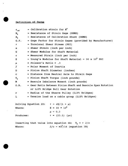
€4= Calibration strain for R'% = Resistance <strong>of</strong> <strong>Strain</strong> Gage (OHMS)% = Resistance <strong>of</strong> Calibration Shunt (OHMS)G.F. = Gage Factor for <strong>Strain</strong> Gages (provided <strong>by</strong> Manufacturer)T = Torsional Shear Stress (PSI)Q = Shear <strong>Strain</strong> (inch per inch)G = Shear Modulus for Shaft MaterialE = Measured <strong>Strain</strong> (inch per inch)E = Young's Modulus for Shaft Material = 30 x lo6 PSIP = Poisson's Ratio = .3J = Polar Moment <strong>of</strong> InertiaD = Pinion Shafk Diameter (inches)c = Distance from Neutral Axis to <strong>Strain</strong> GageTsMG.R.rL= Pinion Shaft Torque (inch pounds)= Bascule Imbalance Moment (inch pounds)= Gear Ratio Between Pinion Shaft and Bascule Span Rotationor Lift Bridge Bull Gear Rotation= Radius <strong>of</strong> <strong>the</strong> Sheave Pulley (Lift <strong>Bridges</strong>)= Tension load on a cable group (Lift <strong>Bridges</strong>)Solving Equation 2D: r = eE/(l + P)Where :E = 30 * lo6p = 0.3Produces :r = (23.1) (PC)Inserting that value into equation 4A: T, = s J/cWhere :J/c = n~~/16 (equation 3B)


