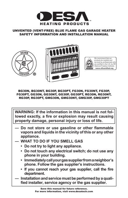
WARNING: If the information in this manual is not fol- lowed ... - Desa
WARNING: If the information in this manual is not fol- lowed ... - Desa
WARNING: If the information in this manual is not fol- lowed ... - Desa

Create successful ePaper yourself
Turn your PDF publications into a flip-book with our unique Google optimized e-Paper software.
AIR FOR COMBUSTIONAND VENTILATIONCont<strong>in</strong>uedDETERMINING FRESH-AIR FLOWFOR HEATER LOCATIONDeterm<strong>in</strong><strong>in</strong>g if You Have a Conf<strong>in</strong>ed orUnconf<strong>in</strong>ed SpaceUse <strong>th<strong>is</strong></strong> work sheet to determ<strong>in</strong>e if you have a conf<strong>in</strong>edor unconf<strong>in</strong>ed space.Space: Includes <strong>the</strong> room <strong>in</strong> which you will <strong>in</strong>stallheater plus any adjo<strong>in</strong><strong>in</strong>g rooms with doorless passagewaysor ventilation grills between <strong>the</strong> rooms.1. Determ<strong>in</strong>e <strong>the</strong> volume of <strong>the</strong> space (length xwidth x height).Length x Width x Height =__________cu. ft.(volume of space)Example: Space size 20 ft. (length) x 16 ft.(width) x 8 ft. (ceil<strong>in</strong>g height) = 2560 cu. ft.(volume of space)<strong>If</strong> additional ventilation to adjo<strong>in</strong><strong>in</strong>g room <strong>is</strong>supplied with grills or open<strong>in</strong>gs, add <strong>the</strong> volumeof <strong>the</strong>se rooms to <strong>the</strong> total volume of <strong>the</strong> space.2. Multiply <strong>the</strong> space volume by 20 to determ<strong>in</strong>e<strong>the</strong> maximum Btu/Hr <strong>the</strong> space can support._______ (volume of space) x 20 = (MaximumBtu/Hr <strong>the</strong> space can support)Example: 2560 cu. ft. (volume of space) x 20 =51,200 (maximum Btu/Hr <strong>the</strong> space can support)3. Add <strong>the</strong> Btu/Hr of all fuel burn<strong>in</strong>g appliances <strong>in</strong><strong>the</strong> space.Vent-free heater ______________ Btu/HrGas water heater* ______________ Btu/HrGas furnace ______________ Btu/HrVented gas heater ______________ Btu/HrGas fireplace logs ______________ Btu/HrO<strong>the</strong>r gas appliances* + __________ Btu/HrTotal= __________ Btu/Hr* Do <strong>not</strong> <strong>in</strong>clude direct-vent gas appliances. Direct-ventdraws combustion air from <strong>the</strong> outdoorsand vents to <strong>the</strong> outdoors.Example:Gas water heater ______________ 40,000 Btu/HrVent-free heater + _____________ 30,000 Btu/HrTotal= _____________ 70,000 Btu/Hr4. Compare <strong>the</strong> maximum Btu/Hr <strong>the</strong> space cansupport with <strong>the</strong> actual amount of Btu/Hr used._______________Btu/Hr (maximum <strong>the</strong> spacecan support)_______________Btu/Hr (actual amount ofBtu/Hr used)Example:51,200 Btu/Hr (maximum <strong>the</strong> space can support)70,000 Btu/Hr (actual amount of Btu/Hr used)The space <strong>in</strong> <strong>the</strong> above example <strong>is</strong> a conf<strong>in</strong>ed spacebecause <strong>the</strong> actual Btu/Hr used <strong>is</strong> more than <strong>the</strong> maximumBtu/Hr <strong>the</strong> space can support. You must provideadditional fresh air. Your options are as <strong>fol</strong>lows:A. Rework worksheet, add<strong>in</strong>g <strong>the</strong> space of an adjo<strong>in</strong><strong>in</strong>groom. <strong>If</strong> <strong>the</strong> extra space provides an unconf<strong>in</strong>edspace, remove door to adjo<strong>in</strong><strong>in</strong>g room or addventilation grills between rooms. See VentilationAir From Inside Build<strong>in</strong>g, page 7.B. Vent room directly to <strong>the</strong> outdoors. See VentilationAir From Outdoors, page 7.C. Install a lower Btu/Hr heater, if lower Btu/Hr sizemakes room unconf<strong>in</strong>ed.<strong>If</strong> <strong>the</strong> actual Btu/Hr used <strong>is</strong> less than <strong>the</strong> maximumBtu/Hr <strong>the</strong> space can support, <strong>the</strong> space <strong>is</strong> an unconf<strong>in</strong>edspace. You will need no additional fresh airventilation.<strong>WARNING</strong>: <strong>If</strong> <strong>the</strong> area <strong>in</strong>which <strong>the</strong> heater may be operated<strong>is</strong> smaller than that def<strong>in</strong>edas an unconf<strong>in</strong>ed space or if <strong>the</strong>build<strong>in</strong>g <strong>is</strong> of unusually tightconstruction, provide adequatecombustion and ventilation airby one of <strong>the</strong> methods described<strong>in</strong> <strong>the</strong> National Fuel Gas Code,ANSI Z223.1/NFPA 54 Section 5.3or applicable local codes.6www.desatech.com 114683-01B
AIR FOR COMBUSTIONAND VENTILATIONCont<strong>in</strong>uedVENTILATION AIRVentilation Air From Inside Build<strong>in</strong>gTh<strong>is</strong> fresh air would come from an adjo<strong>in</strong><strong>in</strong>g unconf<strong>in</strong>edspace. When ventilat<strong>in</strong>g to an adjo<strong>in</strong><strong>in</strong>gunconf<strong>in</strong>ed space, you must provide two permanentopen<strong>in</strong>gs: one with<strong>in</strong> 12” of <strong>the</strong> ceil<strong>in</strong>g andone with<strong>in</strong> 12” of <strong>the</strong> floor on <strong>the</strong> wall connect<strong>in</strong>g<strong>the</strong> two spaces (see options 1 and 2, Figure 2). Youcan also remove door <strong>in</strong>to adjo<strong>in</strong><strong>in</strong>g room (seeoption 3, Figure 2). Follow <strong>the</strong> National Fuel GasCode, ANSI Z223.1/NFPA 54, Section 5.3, Air forCombustion and Ventilation for required size ofventilation grills or ducts.Ventilation Air From OutdoorsProvide extra fresh air by us<strong>in</strong>g ventilation grills orducts. You must provide two permanent open<strong>in</strong>gs:one with<strong>in</strong> 12” of <strong>the</strong> ceil<strong>in</strong>g and one with<strong>in</strong> 12”of <strong>the</strong> floor. Connect <strong>the</strong>se items directly to <strong>the</strong>outdoors or spaces open to <strong>the</strong> outdoors. Thesespaces <strong>in</strong>clude attics and crawl spaces. Follow <strong>the</strong>National Fuel Gas Code, ANSI Z223.1/NFPA 54,Section 5.3, Air for Combustion and Ventilation forrequired size of ventilation grills or ducts.IMPORTANT: Do <strong>not</strong> provide open<strong>in</strong>gs for <strong>in</strong>letor outlet air <strong>in</strong>to attic if attic has a <strong>the</strong>rmostatcontrolledpower vent. Heated air enter<strong>in</strong>g <strong>the</strong> atticwill activate <strong>the</strong> power vent.12"OutletAirInletAirOutletAirInlet AirVentilatedAtticVentilatedCrawl SpaceTo AtticToCrawlSpaceFigure 3 - Ventilation Air from OutdoorsINSTALLATIONNOTICE: Th<strong>is</strong> heater <strong>is</strong> <strong>in</strong>tendedfor use as supplemental heat.Use <strong>th<strong>is</strong></strong> heater along with yourprimary heat<strong>in</strong>g system. Do <strong>not</strong><strong>in</strong>stall <strong>th<strong>is</strong></strong> heater as your primaryheat source. <strong>If</strong> you have acentral heat<strong>in</strong>g system, you mayrun system’s circulat<strong>in</strong>g blowerwhile us<strong>in</strong>g heater. Th<strong>is</strong> will helpcirculate <strong>the</strong> heat throughout <strong>the</strong>house. In <strong>the</strong> event of a poweroutage, you can use <strong>th<strong>is</strong></strong> heateras your primary heat source.<strong>WARNING</strong>: A qualified serviceperson must <strong>in</strong>stall heater.Follow all local codes.VentilationGrills<strong>in</strong>to Adjo<strong>in</strong><strong>in</strong>gRoom,Option 1OrRemoveDoor <strong>in</strong>toAdjo<strong>in</strong><strong>in</strong>gRoom,Option 3Ventilation GrillsInto Adjo<strong>in</strong><strong>in</strong>g Room,Option 2CHECK GAS TYPEUse only <strong>the</strong> correct type of gas (natural or propane/LP).<strong>If</strong> your gas supply <strong>is</strong> <strong>not</strong> <strong>the</strong> correct gastype, do <strong>not</strong> <strong>in</strong>stall heater. Call dealer where youbought heater for proper type heater.12"<strong>WARNING</strong>: Th<strong>is</strong> appliance<strong>is</strong> equipped for (natural or propane/LP)gas. Field conversion<strong>is</strong> <strong>not</strong> permitted.Figure 2 - Ventilation Air from InsideBuild<strong>in</strong>g114683-01B www.desatech.com7
INSTALLATION ITEMSBefore <strong>in</strong>stall<strong>in</strong>g heater, make sure you have <strong>the</strong>items l<strong>is</strong>ted below.• for propane/LP gas, external regulator (suppliedby <strong>in</strong>staller)• pip<strong>in</strong>g (check local codes)• sealant (res<strong>is</strong>tant to propane/LP gas)• equipment shutoff valve *• ground jo<strong>in</strong>t union• sediment trap• tee jo<strong>in</strong>t• pipe wrench• for natural gas, test gauge connection** A CSA design-certified equipment shutoff valvewith 1/8" NPT tap <strong>is</strong> an acceptable alternative totest gauge connection. The optional CSA designcertifiedequipment shutoff valve can be purchasedfrom your dealer. See Accessories, page 30.LOCATING HEATERTh<strong>is</strong> heater <strong>is</strong> designed to be mounted on a wall.<strong>WARNING</strong>: Ma<strong>in</strong>ta<strong>in</strong> <strong>the</strong>m<strong>in</strong>imum clearances shown<strong>in</strong> Figure 4. <strong>If</strong> you can, providegreater clearances from floor,ceil<strong>in</strong>g and jo<strong>in</strong><strong>in</strong>g wall.You can locate heater on floor, away from a wall.An optional floor mount<strong>in</strong>g stand <strong>is</strong> needed. Purchase<strong>the</strong> floor mount<strong>in</strong>g stand from your dealer.See Accessories, page 30.<strong>WARNING</strong>: Never <strong>in</strong>stall <strong>the</strong>heater• <strong>in</strong> a bedroom or bathroom• <strong>in</strong> a recreational vehicle• where curta<strong>in</strong>s, furniture,cloth<strong>in</strong>g or o<strong>the</strong>r flammableobjects are less than 36 <strong>in</strong>chesfrom <strong>the</strong> front, top or sides of<strong>the</strong> heater• as a fireplace <strong>in</strong>sert• <strong>in</strong> high traffic areas• <strong>in</strong> w<strong>in</strong>dy or drafty areasINSTALLATIONCont<strong>in</strong>ued CAUTION: Th<strong>is</strong> heater createswarm air currents. Thesecurrents move heat to wall surfacesnext to heater. Install<strong>in</strong>gheater next to v<strong>in</strong>yl or cloth wallcover<strong>in</strong>gs or operat<strong>in</strong>g heaterwhere impurities (such as, but<strong>not</strong> limited to, tobacco smoke,aromatic candles, clean<strong>in</strong>g fluids,oil or kerosene lamps, etc.) <strong>in</strong><strong>the</strong> air ex<strong>is</strong>t, may d<strong>is</strong>color wallsor cause odors.IMPORTANT: Vent-free heaters add mo<strong>is</strong>ture to<strong>the</strong> air. Although <strong>th<strong>is</strong></strong> <strong>is</strong> beneficial, <strong>in</strong>stall<strong>in</strong>g heater<strong>in</strong> rooms without enough ventilation air may causemildew to form from too much mo<strong>is</strong>ture. See Airfor Combustion and Ventilation, page 5. <strong>If</strong> high humidity<strong>is</strong> experienced, a dehumidifier may be usedto help lower <strong>the</strong> water vapor content <strong>in</strong> <strong>the</strong> air.CAUTION: When <strong>in</strong>stall<strong>in</strong>gheater <strong>in</strong> a home garage• heater pilot and burner must beat least 18 <strong>in</strong>ches above floor• locate heater where mov<strong>in</strong>gvehicle will <strong>not</strong> hit itFor convenience and efficiency, <strong>in</strong>stall heater• where <strong>the</strong>re <strong>is</strong> easy access for operation, <strong>in</strong>spectionand service• <strong>in</strong> coldest part of roomAn optional fan kit <strong>is</strong> available from your dealer.See Accessories, page 30. <strong>If</strong> plann<strong>in</strong>g to use fan,locate heater near an electrical outlet.6"M<strong>in</strong>imumFromSides OfHeaterLeftSideCEILINGFLOOR36"M<strong>in</strong>imumRightSideM<strong>in</strong>imum ToTop SurfaceOf Carpet<strong>in</strong>g,14" Tile Or O<strong>the</strong>rCombustibleMaterialFigure 4 - Mount<strong>in</strong>g Clearances AsViewed From Front of Heater8www.desatech.com 114683-01B
INSTALLATIONCont<strong>in</strong>uedTHERMOSTAT SENSING BULB(Thermostat Models Only)The <strong>the</strong>rmostat sens<strong>in</strong>g bulb has been placedbelow <strong>the</strong> heater.1. Place clamp on <strong>the</strong>rmostat sens<strong>in</strong>g bulb asshown <strong>in</strong> Figure 5. Clamp <strong>is</strong> provided <strong>in</strong>hardware package.2. Snap clamp <strong>in</strong>to upper mount<strong>in</strong>g hole as shown<strong>in</strong> Figure 5. Mount<strong>in</strong>g hole <strong>is</strong> located on lowerleft edge on back of heater. Make sure <strong>the</strong><strong>the</strong>rmostat sens<strong>in</strong>g bulb <strong>is</strong> po<strong>in</strong>t<strong>in</strong>g up.ThermostatSens<strong>in</strong>g BulbClampFigure 5 - Attach<strong>in</strong>g Thermostat Sens<strong>in</strong>gBulbINSTALLING HEATER TO WALLMount<strong>in</strong>g BracketLocate mount<strong>in</strong>g bracket <strong>in</strong> heater carton. Removemount<strong>in</strong>g bracket from heater carton.Figure 6 - Mount<strong>in</strong>g BracketRemov<strong>in</strong>g Front Panel Of Heater1. Remove <strong>the</strong> four pa<strong>in</strong>ted screws, two on eachside of front panel.2. Pull bottom of front panel forward, <strong>the</strong>n out.3. Remove any rema<strong>in</strong><strong>in</strong>g packag<strong>in</strong>g materials.Figure 7 - Remov<strong>in</strong>g Front Panel OfHeaterMethods For Attach<strong>in</strong>g Mount<strong>in</strong>g BracketTo WallOnly use last hole on each end of mount<strong>in</strong>g bracketto attach bracket to wall. These two holes are 14<strong>in</strong>ches apart from <strong>the</strong>ir centers. Attach mount<strong>in</strong>gbracket to wall <strong>in</strong> one of two ways:1. Attach<strong>in</strong>g to wall stud2. Attach<strong>in</strong>g to wall anchorAttach<strong>in</strong>g to Wall Stud: Th<strong>is</strong> method provides <strong>the</strong>strongest hold. Insert mount<strong>in</strong>g screws throughmount<strong>in</strong>g bracket and <strong>in</strong>to wall studs.Attach<strong>in</strong>g to Wall Anchor: Th<strong>is</strong> method allows youto attach mount<strong>in</strong>g bracket to hollow walls (wallareas between studs) or to solid walls (concreteor masonry).Decide which method better suits your needs.Ei<strong>the</strong>r method will provide a secure hold for <strong>the</strong>mount<strong>in</strong>g bracket.Mark<strong>in</strong>g Screw Locations1. Tape mount<strong>in</strong>g bracket to wall where heaterwill be located. Make sure mount<strong>in</strong>g bracket<strong>is</strong> level.<strong>WARNING</strong>: Ma<strong>in</strong>ta<strong>in</strong> m<strong>in</strong>imumclearances shown <strong>in</strong> Figure8, page 10. <strong>If</strong> you can, providegreater clearances from floorand jo<strong>in</strong><strong>in</strong>g wall.114683-01B www.desatech.com9
INSTALLATIONCont<strong>in</strong>ued2. Mark screw locations on wall (see Figure 8).Note: Only mark last hole on each end ofmount<strong>in</strong>g bracket. Insert mount<strong>in</strong>g screwsthrough <strong>the</strong>se holes only.3. Remove tape and mount<strong>in</strong>g bracket fromAdjo<strong>in</strong><strong>in</strong>g Wall12"M<strong>in</strong>.14"Only Insert Mount<strong>in</strong>gScrews Through LastHole On Each EndFloor32"M<strong>in</strong>.Figure 8 - Mount<strong>in</strong>g Bracket ClearancesAttach<strong>in</strong>g Mount<strong>in</strong>g Bracket To WallNote: Wall anchors, mount<strong>in</strong>g screws and spacersare <strong>in</strong> hardware package. The hardware package<strong>is</strong> provided with heater.Attach<strong>in</strong>g To Wall Stud MethodFor attach<strong>in</strong>g mount<strong>in</strong>g bracket to wall studs1. Drill holes at marked locations us<strong>in</strong>g 9/64"drill bit.2. Place mount<strong>in</strong>g bracket onto wall. L<strong>in</strong>e up lasthole on each end of bracket with holes drilled<strong>in</strong> wall.3. Insert mount<strong>in</strong>g screws through bracket and<strong>in</strong>to wall studs.4. Tighten screws until mount<strong>in</strong>g bracket <strong>is</strong>firmly fastened to wall studs.Attach<strong>in</strong>g To Wall Anchor MethodFor attach<strong>in</strong>g mount<strong>in</strong>g bracket to hollow walls(wall areas between studs) or solid walls (concreteor masonry)1. Drill holes at marked locations us<strong>in</strong>g 5/16"drill bit. For solid walls (concrete or masonry),drill at least 1" deep.2. Fold wall anchor as shown <strong>in</strong> Figure 9.3. Insert wall anchor (w<strong>in</strong>gs first) <strong>in</strong>to hole. Tapanchor flush to wall.4. For th<strong>in</strong> walls (1/2" or less), <strong>in</strong>sert red key<strong>in</strong>to wall anchor. Push red key to “pop” openanchor w<strong>in</strong>gs. IMPORTANT: Do <strong>not</strong> hammerkey! For thick walls (over 1/2" thick) or solidwalls, do <strong>not</strong> pop open w<strong>in</strong>gs.5. Place mount<strong>in</strong>g bracket onto wall. L<strong>in</strong>e uplast hole on each end of bracket with wallanchors.6. Insert mount<strong>in</strong>g screws through bracket and<strong>in</strong>to wall anchors.7. Tighten screws until mount<strong>in</strong>g bracket <strong>is</strong>firmly fastened to wall.Figure 9 - Fold<strong>in</strong>gAnchorFigure 10 - Popp<strong>in</strong>gOpen Anchor W<strong>in</strong>gsFor Th<strong>in</strong> WallsPlac<strong>in</strong>g Heater On Mount<strong>in</strong>g Bracket1. Locate two horizontal slots on back panel ofheater.2. Place heater onto mount<strong>in</strong>g bracket. Slidehorizontal slots onto stand-out tabs on mount<strong>in</strong>gbracket.Horizontal SlotsStand-Out TabMount<strong>in</strong>g Bracket(attached to wall)Figure 11 - Mount<strong>in</strong>g Heater OntoMount<strong>in</strong>g Bracket10www.desatech.com 114683-01B
INSTALLATIONCont<strong>in</strong>uedInstall<strong>in</strong>g Bottom Mount<strong>in</strong>g Screws1. Locate two bottom mount<strong>in</strong>g holes. Theseholes are near bottom on back panel of heater(see Figure 12).2. Mark screw locations on wall.3. Remove heater from mount<strong>in</strong>g bracket.4. <strong>If</strong> <strong>in</strong>stall<strong>in</strong>g bottom mount<strong>in</strong>g screws <strong>in</strong>tohollow or solid wall, <strong>in</strong>stall wall anchors.Follow steps 1 through 4 under Attach<strong>in</strong>g ToWall Anchor Method, page 10.<strong>If</strong> <strong>in</strong>stall<strong>in</strong>g bottom mount<strong>in</strong>g screw <strong>in</strong>to wallstud, drill holes at marked locations us<strong>in</strong>g9/64" drill bit.5. Replace heater onto mount<strong>in</strong>g bracket.6. Place spacers between bottom mount<strong>in</strong>g holesand wall anchor or drilled hole.7. Hold spacer <strong>in</strong> place with one hand. With o<strong>the</strong>rhand, <strong>in</strong>sert mount<strong>in</strong>g screw through bottommount<strong>in</strong>g hole and spacer. Place tip of screw<strong>in</strong> open<strong>in</strong>g of wall anchor or drilled hole.8. Tighten both screws until heater <strong>is</strong> firmlysecured to wall. Do <strong>not</strong> over tighten.Note: Do <strong>not</strong> replace front panel at <strong>th<strong>is</strong></strong> time.Replace front panel after mak<strong>in</strong>g gas connectionsand check<strong>in</strong>g for leaks (see pages 12through 14).HeaterFront ViewSide ViewWallSpacerFigure 12 - Install<strong>in</strong>g Bottom Mount<strong>in</strong>gScrews114683-01B www.desatech.com11
INSTALLATIONCont<strong>in</strong>uedCONNECTING TO GAS SUPPLY<strong>WARNING</strong>: Th<strong>is</strong> appliancerequires a 3/8" NPT (NationalPipe Thread) <strong>in</strong>let connection to<strong>the</strong> pressure regulator.<strong>WARNING</strong>: A qualified serviceperson must connect heaterto gas supply. Follow all localcodes.<strong>WARNING</strong>: For natural gas,never connect heater to private (nonutility)gas wells. Th<strong>is</strong> gas <strong>is</strong> commonlyknown as wellhead gas.IMPORTANT: For natural gas, check gas l<strong>in</strong>epressure before connect<strong>in</strong>g heater to gas l<strong>in</strong>e. Gasl<strong>in</strong>e pressure must be no greater than 10.5 <strong>in</strong>ches ofwater. <strong>If</strong> gas l<strong>in</strong>e pressure <strong>is</strong> higher, heater regulatordamage could occur.CAUTION: For propane/LPgas, never connect heater directlyto <strong>the</strong> propane/LP supply. Th<strong>is</strong>heater requires an external regulator(<strong>not</strong> supplied). Install <strong>the</strong>external regulator between <strong>the</strong>heater and propane/LP supply.For propane/LP gas, <strong>the</strong> <strong>in</strong>staller must supply anexternal regulator. The external regulator willreduce <strong>in</strong>com<strong>in</strong>g gas pressure. You must reduce<strong>in</strong>com<strong>in</strong>g gas pressure to between 11 and 14 <strong>in</strong>chesof water. <strong>If</strong> you do <strong>not</strong> reduce <strong>in</strong>com<strong>in</strong>g gas pressure,heater regulator damage could occur. Install<strong>the</strong> external regulator with <strong>the</strong> vent po<strong>in</strong>t<strong>in</strong>g downas shown <strong>in</strong> Figure 14. Po<strong>in</strong>t<strong>in</strong>g <strong>the</strong> vent downprotects it from freez<strong>in</strong>g ra<strong>in</strong> or sleet.CAUTION: Use only new,black iron or steel pipe. Internally-t<strong>in</strong>nedcopper tub<strong>in</strong>g maybe used <strong>in</strong> certa<strong>in</strong> areas. Checkyour local codes. Use pipe oflarge enough diameter to allowproper gas volume to heater. <strong>If</strong>pipe <strong>is</strong> too small, undue loss ofvolume will occur.Typical Inlet Pipe Diameter30,000 Btu/Hr Models - 1/2" or greaterInstallation must <strong>in</strong>clude equipment shutoff valve,union and plugged 1/8" NPT tap. Locate NPT tapwith<strong>in</strong> reach for test gauge hook up. NPT tap mustbe upstream from heater (see Figure 15, page 13).IMPORTANT: Install an equipment shutoff valve<strong>in</strong> an accessible location. The equipment shutoffvalve <strong>is</strong> for turn<strong>in</strong>g on or shutt<strong>in</strong>g off <strong>the</strong> gas to<strong>the</strong> appliance.Apply pipe jo<strong>in</strong>t sealant lightly to male NPTthreads. Th<strong>is</strong> will prevent excess sealant fromgo<strong>in</strong>g <strong>in</strong>to pipe. Excess sealant <strong>in</strong> pipe could result<strong>in</strong> clogged heater valves.<strong>WARNING</strong>: Use pipe jo<strong>in</strong>tsealant that <strong>is</strong> res<strong>is</strong>tant to liquidpetroleum (LP) gas.Install sediment trap <strong>in</strong> supply l<strong>in</strong>e as shown <strong>in</strong>Figure 15, page 13. Locate sediment trap whereit <strong>is</strong> with<strong>in</strong> reach for clean<strong>in</strong>g. Locate sedimenttrap where trapped matter <strong>is</strong> <strong>not</strong> likely to freeze.A sediment trap traps mo<strong>is</strong>ture and contam<strong>in</strong>ants.Th<strong>is</strong> keeps <strong>the</strong>m from go<strong>in</strong>g <strong>in</strong>to heater controls. <strong>If</strong>sediment trap <strong>is</strong> <strong>not</strong> <strong>in</strong>stalled or <strong>is</strong> <strong>in</strong>stalled wrong,heater may <strong>not</strong> run properly.Propane/LPSupply TankExternal RegulatorVentPo<strong>in</strong>t<strong>in</strong>gDownFigure 14 - External Regulator With VentPo<strong>in</strong>t<strong>in</strong>g Down12www.desatech.com 114683-01B
Sediment TrapIMPORTANT: Hold <strong>the</strong> pressure regulator withwrench when connect<strong>in</strong>g it to gas pip<strong>in</strong>g and/orfitt<strong>in</strong>gs. Do <strong>not</strong> over tighten pipe connection toregulator. The regulator body could be damaged.Test Gauge Connection*PressureRegulator3/8" NPTPipe NippleINSTALLATIONTee Jo<strong>in</strong>tReducerBush<strong>in</strong>g to1/8" NPT1/8" NPTPlug TapTee Jo<strong>in</strong>tPipeNippleCapCont<strong>in</strong>ued <strong>WARNING</strong>: Never use anHeaterCab<strong>in</strong>etGround Jo<strong>in</strong>tUnionEquipmentShutoffValve*3" M<strong>in</strong>.Natural GasFrom Gas Meter(4" W.C. to 10.5" W.C.Pressure)Propane/LPFrom ExternalRegulator(11" W.C. to 14" W.C.Pressure)Figure 15 - Gas Connection* A CSA design-certified equipment shutoff valvewith 1/8" NPT tap <strong>is</strong> an acceptable alternative totest gauge connection. Purchase <strong>the</strong> optional CSAdesign-certified equipment shutoff valve from yourdealer. See Accessories, page 30.CHECKING GAS CONNECTIONS<strong>WARNING</strong>: Test all gas pip<strong>in</strong>gand connections, <strong>in</strong>ternal andexternal to unit, for leaks after<strong>in</strong>stall<strong>in</strong>g or servic<strong>in</strong>g. Correctall leaks at once.open flame to check for a leak.Apply a noncorrosive leak detectionfluid to all jo<strong>in</strong>ts. Bubblesform<strong>in</strong>g show a leak. Correct allleaks at once.CAUTION: For propane/LPgas, make sure external regulatorhas been <strong>in</strong>stalled betweenpropane/LP supply and heater.See guidel<strong>in</strong>es under Connect<strong>in</strong>gto Gas Supply, page 12.PRESSURE TESTING GAS SUPPLYPIPING SYSTEMTest Pressures In Excess Of 1/2 PSIG(3.5 kPa)1. D<strong>is</strong>connect appliance with its appliance ma<strong>in</strong>gas valve (control valve) and equipmentshutoff valve from gas supply pip<strong>in</strong>g system.Pressures <strong>in</strong> excess of 1/2 psig will damageheater regulator.2. Cap off open end of gas pipe where equipmentshutoff valve was connected.3. Pressurize supply pip<strong>in</strong>g system by ei<strong>the</strong>ropen<strong>in</strong>g propane/LP supply tank valve forpropane/LP gas or open<strong>in</strong>g ma<strong>in</strong> gas valvelocated on or near gas meter for natural gasor us<strong>in</strong>g compressed air.4. Check all jo<strong>in</strong>ts of gas supply pip<strong>in</strong>g system.Apply a noncorrosive leak detection fluid toall jo<strong>in</strong>ts. Bubbles form<strong>in</strong>g show a leak.5. Correct all leaks at once.6. Reconnect heater and equipment shutoffvalve to gas supply. Check reconnected fitt<strong>in</strong>gsfor leaks.Test Pressures Equal To or Less Than1/2 PSIG (3.5 kPa)1. Close equipment shutoff valve (see Figure 16).EquipmentShutoff ValveOpenClosedFigure 16 - Equipment Shutoff Valve114683-01B www.desatech.com13
OPERATING HEATERCont<strong>in</strong>ued6. With control knob pressed <strong>in</strong>, push downand release ignitor button. Th<strong>is</strong> will lightpilot. The pilot <strong>is</strong> attached to <strong>the</strong> front ofburner. The pilot <strong>is</strong> attached to <strong>the</strong> front of<strong>the</strong> burner. <strong>If</strong> needed, keep press<strong>in</strong>g ignitorbutton until pilot lights.Note: <strong>If</strong> pilot does <strong>not</strong> stay lit, refer toTroubleshoot<strong>in</strong>g, page 20. Also contact aqualified service person or gas supplier forrepairs. Until repairs are made, light pilotwith match. To light pilot with match, seeManual Light<strong>in</strong>g Procedure.7. Keep control knob pressed <strong>in</strong> for 30 secondsafter light<strong>in</strong>g pilot. After 30 seconds, releasecontrol knob.• <strong>If</strong> control knob does <strong>not</strong> pop up whenreleased, contact a qualified service personor gas supplier for repairs.Note: <strong>If</strong> pilot goes out, repeat steps 3through 7. Th<strong>is</strong> heater has a safety <strong>in</strong>terlocksystem. Wait one (1) m<strong>in</strong>ute beforelight<strong>in</strong>g pilot aga<strong>in</strong>.8. Turn control knob counterclockw<strong>is</strong>eto desired heat<strong>in</strong>g level. The ma<strong>in</strong> burnershould light. Set control knob to any heatlevel between 1 and 5.CAUTION: Do <strong>not</strong> try to adjus<strong>the</strong>at<strong>in</strong>g levels by us<strong>in</strong>g <strong>the</strong>equipment shutoff valve.ThermocoupleIgnitor ElectrodePilot BurnerFigure 22 - Pilot (actual pilot may vary)TO TURN OFF GASTO APPLIANCEShutt<strong>in</strong>g Off Heater1. Turn control knob clockw<strong>is</strong>e to <strong>the</strong>OFF position.2. Turn off all electric power to <strong>the</strong> applianceif service <strong>is</strong> to be performed.Shutt<strong>in</strong>g Off Burner Only (pilot stays lit)Turn control knob clockw<strong>is</strong>e to <strong>the</strong>PILOT position.THERMOSTAT CONTROLOPERATIONThe <strong>the</strong>rmostatic control used on <strong>the</strong>se modelsdiffers from standard <strong>the</strong>rmostats. Standard<strong>the</strong>rmostats simply turn on and off <strong>the</strong> burner.The <strong>the</strong>rmostat used on <strong>th<strong>is</strong></strong> heater senses <strong>the</strong>room temperature. The <strong>the</strong>rmostat adjusts <strong>the</strong>amount of gas flow to <strong>the</strong> burner. Th<strong>is</strong> <strong>in</strong>creasesor decreases <strong>the</strong> burner flame height. At times<strong>the</strong> room may exceed <strong>the</strong> set temperature. <strong>If</strong> so,<strong>the</strong> burner will shut off. The burner will cycleback on when room temperature drops below <strong>the</strong>set temperature. The control knob can be set toany heat level between 1 and 5. Select<strong>in</strong>g <strong>the</strong> 5sett<strong>in</strong>g will cause <strong>the</strong> burner to rema<strong>in</strong> fully onwithout modulat<strong>in</strong>g down <strong>in</strong> most cases.Note: The <strong>the</strong>rmostat sens<strong>in</strong>g bulb measures<strong>the</strong> temperature of air near <strong>the</strong> heater cab<strong>in</strong>et.Th<strong>is</strong> may <strong>not</strong> always agree with room temperature(depend<strong>in</strong>g on hous<strong>in</strong>g construction,<strong>in</strong>stallation location, room size, open air temperatures,etc.). Frequent use of your heater willlet you determ<strong>in</strong>e your own comfort levels.MANUAL LIGHTINGPROCEDURE1. Remove front panel (see Figure 7, page 9).2. Follow steps 1 through 5 under Light<strong>in</strong>gInstructions, page 16.3. With control knob pressed <strong>in</strong>, strike match.Hold match to pilot until pilot lights.4. Keep control knob pressed <strong>in</strong> for 30 secondsafter light<strong>in</strong>g pilot. After 30 seconds, releasecontrol knob. Now <strong>fol</strong>low step 8, underLight<strong>in</strong>g Instructions, column 1.5. Replace front panel.114683-01B www.desatech.com17
INSPECTING HEATERCheck pilot flame pattern and burner flame patternoften.PILOT FLAME PATTERNFigure 23 shows a correct pilot flame pattern.Figure 24 shows an <strong>in</strong>correct pilot flame pattern.The <strong>in</strong>correct pilot flame <strong>is</strong> <strong>not</strong> touch<strong>in</strong>g <strong>the</strong><strong>the</strong>rmocouple. Th<strong>is</strong> will cause <strong>the</strong> <strong>the</strong>rmocoupleto cool. When <strong>the</strong> <strong>the</strong>rmocouple cools, <strong>the</strong> heaterwill shut down.<strong>If</strong> pilot flame pattern <strong>is</strong> <strong>in</strong>correct, as shown <strong>in</strong>Figure 24• turn heater off (see To Turn Off Gas to Appliance,page 16 or 17)• see Troubleshoot<strong>in</strong>g, page 20Note: The pilot flame on natural gas units willhave a slight curve, but flame should be blue andhave no yellow or orange color.ThermocoupleFigure 23 - Correct Pilot Flame PatternThermocoupleBlue FlamePilot BurnerYellow FlamePilotBurnerFigure 24 - Incorrect Pilot Flame PatternBURNER FLAME PATTERN<strong>WARNING</strong>: <strong>If</strong> yellow tipp<strong>in</strong>goccurs, your heater could produce<strong>in</strong>creased levels of carbonmonoxide.NOTICE: Do <strong>not</strong> m<strong>is</strong>take orangeflames with yellow tipp<strong>in</strong>g. Dirtor o<strong>the</strong>r f<strong>in</strong>e particles enter <strong>the</strong>heater and burn caus<strong>in</strong>g briefpatches of orange flame.Figure 25 shows a correct burner flame pattern.Figure 26 shows an <strong>in</strong>correct burner flame pattern.The <strong>in</strong>correct burner flame pattern shows yellowtipp<strong>in</strong>g of <strong>the</strong> flame. It also shows <strong>the</strong> flame higherthan 1/2 <strong>the</strong> heat shield height.<strong>If</strong> burner flame pattern <strong>is</strong> <strong>in</strong>correct, as shown <strong>in</strong>Figure 26• turn heater off (see To Turn Off Gas To Appliance,page 16 or 17)• see Troubleshoot<strong>in</strong>g, page 20BlueFlameHeat1/ 2 ShieldHeightFigure 25 - Correct Burner Flame PatternFigure 26 - Incorrect Burner FlamePatternYellowTipp<strong>in</strong>gHeat1/2 ShieldHeight18www.desatech.com 114683-01B
CLEANING ANDMAINTENANCE<strong>WARNING</strong>: Turn off heaterand let cool before clean<strong>in</strong>g.CAUTION: You must keepcontrol areas, burner and circulat<strong>in</strong>gair passageways of heaterclean. Inspect <strong>the</strong>se areas ofheater before each use. Haveheater <strong>in</strong>spected yearly by aqualified service person. Heatermay need more frequent clean<strong>in</strong>gdue to excessive l<strong>in</strong>t fromcarpet<strong>in</strong>g, bedd<strong>in</strong>g material, pethair, etc.<strong>WARNING</strong>: Failure to keep<strong>the</strong> primary air open<strong>in</strong>g(s) of<strong>the</strong> burner(s) clean may result <strong>in</strong>soot<strong>in</strong>g and property damage.ODS/PILOT AND BURNERUse a vacuum cleaner, pressurized air or small,soft br<strong>is</strong>tled brush to clean.BURNER PILOT AIR INLETThe primary air <strong>in</strong>let hole allows <strong>the</strong> properamount of air to mix with <strong>the</strong> gas. Th<strong>is</strong> provides aclean burn<strong>in</strong>g flame. Keep <strong>th<strong>is</strong></strong> hole clear of dust,dirt and l<strong>in</strong>t. Clean <strong>th<strong>is</strong></strong> air <strong>in</strong>let hole prior to eachheat<strong>in</strong>g season. A blocked air hole will create soot.We recommend that you clean <strong>the</strong> unit every threemonths dur<strong>in</strong>g operation and have heater <strong>in</strong>spectedyearly by a qualified service person.We also recommend that you keep <strong>the</strong> burnertube and pilot assembly clean and free of dust anddirt. To clean <strong>the</strong>se parts we recommend us<strong>in</strong>gcompressed air no greater than 30 PSI. Your localcomputer store, hardware store or home centermay carry compressed air <strong>in</strong> a can. You can use avacuum cleaner <strong>in</strong> <strong>the</strong> blow position. <strong>If</strong> us<strong>in</strong>g compressedair <strong>in</strong> a can, please <strong>fol</strong>low <strong>the</strong> directions on<strong>the</strong> can. <strong>If</strong> you donʼt <strong>fol</strong>low directions on <strong>the</strong> can,you could damage <strong>the</strong> pilot assembly.1. Shut off <strong>the</strong> unit, <strong>in</strong>clud<strong>in</strong>g <strong>the</strong> pilot. Allow<strong>the</strong> unit to cool for at least thirty m<strong>in</strong>utes.2. Inspect burner, pilot for dust and dirt.3. Blow air through <strong>the</strong> ports/slots and holes <strong>in</strong><strong>the</strong> burner.4. Never <strong>in</strong>sert objects <strong>in</strong>to <strong>the</strong> pilot tube.Clean <strong>the</strong> pilot assembly also. A yellow tip on <strong>the</strong>pilot flame <strong>in</strong>dicates dust and dirt <strong>in</strong> <strong>the</strong> pilot assembly.There <strong>is</strong> a small pilot air <strong>in</strong>let about two<strong>in</strong>ches from where <strong>the</strong> pilot flame comes out of<strong>the</strong> pilot assembly (see Figure 27). With <strong>the</strong> unitoff, lightly blow air through <strong>the</strong> air <strong>in</strong>let. You mayblow through a dr<strong>in</strong>k<strong>in</strong>g straw if compressed air<strong>is</strong> <strong>not</strong> available.Pilot Air InletPilot AssemblyFigure 27 - Pilot Inlet Air(Propane/LP Pilot Shown)CABINETAir PassagewaysUse a vacuum cleaner or pressurized air toclean.ExteriorUse a soft cloth dampened with a mild soap andwater mixture. Wipe <strong>the</strong> cab<strong>in</strong>et to remove dust.114683-01B www.desatech.com19
OBSERVED PROBLEMODS/pilot lights but flame goesout when control knob <strong>is</strong> releasedTROUBLESHOOTINGCont<strong>in</strong>uedPOSSIBLE CAUSE1. Control knob <strong>not</strong> fully pressed <strong>in</strong>2. Control knob <strong>not</strong> pressed <strong>in</strong>long enough3. Safety <strong>in</strong>terlock system hasbeen triggered4. Equipment shutoff valve <strong>not</strong>fully open5. Thermocouple connectionloose at control valve6. Pilot flame <strong>not</strong> touch<strong>in</strong>g <strong>the</strong>rmocouple,which allows <strong>the</strong>rmocoupleto cool, caus<strong>in</strong>gpilot flame to go out. Th<strong>is</strong>problem could be caused byone or both of <strong>the</strong> <strong>fol</strong>low<strong>in</strong>g:A) Low gas pressureB) Dirty or partially cloggedODS/pilot7. Thermocouple damaged8. Control valve damagedREMEDY1. Press <strong>in</strong> control knob fully2. After ODS/pilot lights, keep controlknob pressed <strong>in</strong> 30 seconds3. Wait one m<strong>in</strong>ute for safety <strong>in</strong>terlocksystem to reset. Repeatignition operation4. Fully open equipment shutoffvalve5. Hand tighten until snug, <strong>the</strong>ntighten 1/4 turn more6. A) Contact local natural orpropane/LP gas companyB) Clean ODS/pilot (seeClean<strong>in</strong>g and Ma<strong>in</strong>tenance,page 19) or replace ODS/pilotassembly7. Replace pilot assembly8. Replace control valveBurner does <strong>not</strong> light after ODS/pilot <strong>is</strong> litDelayed ignition of burnerBurner backfir<strong>in</strong>g dur<strong>in</strong>g combustion1. Burner orifice <strong>is</strong> clogged2. Inlet gas pressure <strong>is</strong> too low1. Mani<strong>fol</strong>d pressure <strong>is</strong> too low2. Burner orifice <strong>is</strong> clogged1. Burner orifice <strong>is</strong> clogged ordamaged2. Burner damaged3. Gas regulator defective1. Clean burner (see Clean<strong>in</strong>gand Ma<strong>in</strong>tenance, page 19)or replace burner orifice2. Contact local natural or propane/LPgas company1. Contact local natural or propane/LPgas company2. Clean burner (see Clean<strong>in</strong>gand Ma<strong>in</strong>tenance, page 19)or replace burner orifice1. Clean burner (see Clean<strong>in</strong>gand Ma<strong>in</strong>tenance, page 19)or replace burner orifice2. Replace burner3. Replace gas regulator114683-01B www.desatech.com21
TROUBLESHOOTINGCont<strong>in</strong>ued<strong>WARNING</strong>: <strong>If</strong> you smell gas• Shut off gas supply.• Do <strong>not</strong> try to light any appliance.• Do <strong>not</strong> touch any electrical switch; do <strong>not</strong> use any phone <strong>in</strong> yourbuild<strong>in</strong>g.• Immediately call your gas supplier from a neighbor’s phone. Follow<strong>the</strong> gas supplier’s <strong>in</strong>structions.• <strong>If</strong> you can<strong>not</strong> reach your gas supplier, call <strong>the</strong> fire department.IMPORTANT: Operat<strong>in</strong>g heater where impurities <strong>in</strong> air ex<strong>is</strong>t may create odors. Clean<strong>in</strong>g supplies,pa<strong>in</strong>t, pa<strong>in</strong>t remover, cigarette smoke, cements and glues, new carpet or textiles, etc., create fumes.OBSERVED PROBLEMHeater produces unwantedodorsPOSSIBLE CAUSE REMEDY1. Heater burn<strong>in</strong>g vapors frompa<strong>in</strong>t, hair spray, glues, etc.(see IMPORTANT statementabove)2. Low fuel supply (propane/LPgas only)3. Gas leak. See Warn<strong>in</strong>gstatement above1. Ventilate room. Stop us<strong>in</strong>godor caus<strong>in</strong>g products whileheater <strong>is</strong> runn<strong>in</strong>g2. Refill supply tank3. Locate and correct all leaks(see Check<strong>in</strong>g Gas Connections,page 13)Heater shuts off <strong>in</strong> use (ODSoperates)Gas odor even when control knob<strong>is</strong> <strong>in</strong> OFF position1. Not enough fresh air <strong>is</strong>available2. Low l<strong>in</strong>e pressure3. ODS/pilot i s p a r t i a l l yclogged1. Gas leak. See Warn<strong>in</strong>gstatement above2. Control valve defective1. Open w<strong>in</strong>dow and/or door forventilation2. Contact local natural or propane/LPgas company3. Clean ODS/pilot (see Clean<strong>in</strong>gand Ma<strong>in</strong>tenance, page 19)1. Locate and correct all leaks(see Check<strong>in</strong>g Gas Connections,page 13)2. Replace control valveGas odor dur<strong>in</strong>g combustion1. Foreign matter between controlvalve and burner2. Gas leak. See Warn<strong>in</strong>gstatement above1. Take apart gas tub<strong>in</strong>g andremove foreign matter2. Locate and correct all leaks(see Check<strong>in</strong>g Gas Connections,page 13)Mo<strong>is</strong>ture/condensation <strong>not</strong>icedon w<strong>in</strong>dows1. Not enough combustion/ventilationair1. Refer to Air for Combustionand Ventilation requirements(page 5)114683-01B www.desatech.com23
SPECIFICATIONSBG30N, FG30N, GG30N, RG30N, GMG30NBG30NT, FG30NT, GG30NT, RG30NT, GMG30NTBtu (Variable) 15,000/30,000Type GasNatural OnlyIgnitionPiezoPressure Regulator Sett<strong>in</strong>g3" W.C.Inlet Gas Pressure (<strong>in</strong>. of water)Maximum 10.5"M<strong>in</strong>imum 4"Dimensions, Inches (H x W x D)Heater 24 1 /4 x 25 3 /4 x 7Carton 26 3 /8 x 28 1 /8 x 10Weight (pounds)Heater 28Shipp<strong>in</strong>g 33BG30P, FG30P, GG30P, RG30P, GMG30PBG30PT, FG30PT, GG30PT, RG30PT, GMG30PTBtu (Variable) 15,000/30,000Type GasPropane/LP OnlyIgnitionPiezoPressure Regulator Sett<strong>in</strong>g8" W.C.Inlet Gas Pressure (<strong>in</strong>. of water)Maximum 14"M<strong>in</strong>imum 11"Dimensions, Inches (H x W x D)Heater (Includes knobs & grill) 24 1 /4 x 25 3 /4 x 7Carton 26 3 /8 x 28 1 /8 x 10Weight (pounds)Heater 28Shipp<strong>in</strong>g 3324www.desatech.com 114683-01B
SERVICE HINTSWhen Gas Pressure Is Too Low• pilot will <strong>not</strong> stay lit• burner will have delayed ignition• heater will <strong>not</strong> produce specified heat• propane/LP gas supply may be lowYou may feel your gas pressure <strong>is</strong> too low. <strong>If</strong>so, contact your local natural or propane/LPgas supplier.TECHNICAL SERVICEYou may have fur<strong>the</strong>r questions about <strong>in</strong>stallation,operation or troubleshoot<strong>in</strong>g. <strong>If</strong> so, contact DESAHeat<strong>in</strong>g Productsʼ Technical Service Departmentat 1-866-672-6040. When call<strong>in</strong>g please have yourmodel and serial numbers of your heater ready.You can also v<strong>is</strong>it DESA Heat<strong>in</strong>g Productsʼ technicalservice web site at www.desatech.com.SERVICE PUBLICATIONSYou can purchase a service <strong>manual</strong> from <strong>the</strong> addressl<strong>is</strong>ted on <strong>the</strong> back page of <strong>th<strong>is</strong></strong> <strong>manual</strong>. Send a checkfor $5.00 payable to DESA Heat<strong>in</strong>g ProductsREPLACEMENT PARTSNote: Use only orig<strong>in</strong>al replacement parts. Th<strong>is</strong>will protect your warranty coverage for partsreplaced under warranty.PARTS UNDER WARRANTYContact authorized dealers of <strong>th<strong>is</strong></strong> product. <strong>If</strong><strong>the</strong>y canʼt supply orig<strong>in</strong>al replacement part(s),call DESA Heat<strong>in</strong>g Productsʼ Technical ServiceDepartment at 1-866-672-6040.When call<strong>in</strong>g DESA Heat<strong>in</strong>g Products, haveready• your name• your address• model and serial numbers of your heater• how heater was malfunction<strong>in</strong>g• type of gas used (propane/LP or natural gas)• purchase dateUsually, we will ask you to return <strong>the</strong> part to <strong>the</strong>factory.PARTS NOT UNDER WARRANTYContact authorized dealers of <strong>th<strong>is</strong></strong> product. <strong>If</strong> <strong>the</strong>ycanʼt supply orig<strong>in</strong>al replacement part(s), ei<strong>the</strong>rcontact your nearest Parts Central (see page 31)or call DESA Heat<strong>in</strong>g Products at 1-866-672-6040for referral <strong><strong>in</strong>formation</strong>.When call<strong>in</strong>g DESA Heat<strong>in</strong>g Products, haveready• model number of your heater• <strong>the</strong> replacement part number114683-01B www.desatech.com25
ILLUSTRATED PARTS BREAKDOWNMODELSBG30N, BG30P, FG30N, FG30P,GG30N, GG30P, RG30N, RG30P,GMG30N, GMG30P715201421591217139111014181983616226www.desatech.com 114683-01B
PARTS LISTTh<strong>is</strong> l<strong>is</strong>t conta<strong>in</strong>s replaceable parts used <strong>in</strong> your heater. When order<strong>in</strong>g parts, <strong>fol</strong>low <strong>the</strong> <strong>in</strong>structionsl<strong>is</strong>ted under Replacement Parts on page 25 of <strong>th<strong>is</strong></strong> <strong>manual</strong>.PART NUMBERBG30N BG30PKEY FG30N FG30P RG30N RG30PNO. GG30N GG30P GMG30N GMG30P DESCRIPTION QTY.1 097159-04 097159-04 097159-04 097159-04 Piezo Ignitor 12 107676-01 107676-01 107676-01 107676-01 Front Panel 13 103476-02 103476-02 103476-02 103476-02 Grill Guard 14 110038-05 110038-06 110038-05 110038-06 Control Valve 15 098508-01 098508-01 098508-01 098508-01 Valve Reta<strong>in</strong>er Nut 16 104658-01 104658-01 104658-01 104658-01 Heat Shield 17 ** ** ** ** Cab<strong>in</strong>et 18 107894-11 107894-11 107894-11 107894-11 Deflector Assembly 19 098271-09 098271-09 098271-09 098271-09 Ignitor Cable 110 098249-01 098249-01 098249-01 098249-01 Nut 211 110803-01 110803-02 110803-01 110803-02 ODS/Pilot Assembly 1110186-01 110186-01 110186-01 110186-01 Thermocouple Kit 112 103447-01 103447-01 103447-01 103447-01 Burner 113 099387-05 099387-05 099387-05 099387-05 Pilot Tub<strong>in</strong>g 114 103845-08 103845-07 103845-08 103845-07 Injector 115 099066-02 099066-02 099066-02 099066-02 Mount<strong>in</strong>g Bracket 116 099415-17 099415-18 099415-17 099415-18 Gas Regulator 117 NJF 8C NJF 8C NJF 8C NJF 8C Hex Nut 118 103570-04 103570-04 103570-04 103570-04 Outlet Tub<strong>in</strong>g 119 103572-03 103572-03 103572-03 103572-03 Inlet Tub<strong>in</strong>g 120 109303-03 109303-03 109303-03 109303-03 Baffle 121 098354-02 098354-02 098354-02 098354-02 Control Knob 1PARTS AVAILABLE — NOT SHOWN100642-03 100642-03 100642-03 100642-03 Hardware Assembly 1105345-01 105345-01 105345-01 105345-01 Cable Tie 1107888-01 107888-01 107888-01 107888-01 Control Position Label 1111051-01 111051-01 111051-01 111051-01 Light<strong>in</strong>g Instruction Label 1** Not a field replaceable part.114683-01B www.desatech.com27
ILLUSTRATED PARTS BREAKDOWNMODELSBG30NT, BG30PT, FG30NT, FG30PT,GG30NT, GG30PT, RG30NT, RG30PT,GMG30NT, GMG30PT715514101217139111014181983616228www.desatech.com 114683-01B
PARTS LISTTh<strong>is</strong> l<strong>is</strong>t conta<strong>in</strong>s replaceable parts used <strong>in</strong> your heater. When order<strong>in</strong>g parts, <strong>fol</strong>low <strong>the</strong> <strong>in</strong>structionsl<strong>is</strong>ted under Replacement Parts on page 25 of <strong>th<strong>is</strong></strong> <strong>manual</strong>.PART NUMBERBG30NT BG30PTKEY FG30NT FG30PT RG30NT RG30PTNO. GG30NT GG30PT GMG30NT GMG30PT DESCRIPTION QTY.1 097159-04 097159-04 097159-04 097159-04 Piezo Ignitor 12 107676-01 107676-01 107676-01 107676-01 Front Panel 13 103476-02 103476-02 103476-02 103476-02 Grill Guard 14 098522-12 098522-13 098522-12 098522-13 Thermostat Gas Valve 15 109303-03 109303-03 109303-03 109303-03 Baffle 16 104658-01 104658-01 104658-01 104658-01 Heat Shield 17 ** ** ** ** Cab<strong>in</strong>et 18 107894-11 107894-11 107894-11 107894-11 Deflector Assembly 19 098271-09 098271-09 098271-09 098271-09 Ignitor Cable 110 098249-01 098249-01 098249-01 098249-01 Nut 211 110803-01 110803-02 110803-01 110803-02 ODS/Pilot Assembly 1110186-01 110186-01 110186-01 110186-01 Thermocouple Kit 112 103447-01 103447-01 103447-01 103447-01 Burner 113 099387-03 099387-03 099387-03 099387-03 Pilot Tub<strong>in</strong>g 114 103845-08 103845-07 103845-08 103845-07 Injector 115 099066-02 099066-02 099066-02 099066-02 Mount<strong>in</strong>g Bracket 116 099415-17 099415-18 099415-17 099415-18 Gas Regulator 117 NJF 8C NJF 8C NJF 8C NJF 8C Hex Nut 118 103255-02 103255-02 103255-02 103255-02 Outlet Tub<strong>in</strong>g 119 103256-02 103256-02 103256-02 103256-02 Inlet Tub<strong>in</strong>g 1PARTS AVAILABLE — NOT SHOWN100642-03 100642-03 100642-03 100642-03 Hardware Assembly 1107888-01 107888-01 107888-01 107888-01 Control Position Label 1111051-01 111051-01 111051-01 111051-01 Light<strong>in</strong>g Instruction Label 1** Not a field replaceable part.114683-01B www.desatech.com29
ACCESSORIESPurchase <strong>the</strong>se heater accessories from your localdealer. <strong>If</strong> <strong>the</strong>y can <strong>not</strong> supply <strong>the</strong>se accessories, ei<strong>the</strong>rcontact your nearest Parts Central (see page 31) orcall DESA Heat<strong>in</strong>g Products at 1-866-672-6040for referral <strong><strong>in</strong>formation</strong>. You can also write to <strong>the</strong>address l<strong>is</strong>ted on <strong>the</strong> back page of <strong>th<strong>is</strong></strong> <strong>manual</strong>.EQUIPMENT SHUTOFF VALVEGA5010For all models. Equipment shutoff valve with1/8" NPT tap.FAN KITS - GA3250TFor all models. Provides better heat d<strong>is</strong>tribution.Makes heater more efficient. Complete <strong>in</strong>stallationand operat<strong>in</strong>g <strong>in</strong>structions <strong>in</strong>cluded.Thermostatically-controlled, blower turns itself onand off as required.ELECTRONIC IGNITOR KIT - GA435Not ShownFor all piezo ignitor models. Provides easierlight<strong>in</strong>g of <strong>the</strong> pilot.30www.desatech.com 114683-01B
PARTS CENTRALSThese Parts Centrals are privately owned bus<strong>in</strong>esses. They have agreed to support our customerʼs needsby provid<strong>in</strong>g orig<strong>in</strong>al replacement parts and accessories.Tool & Equipment, Co.5 Manila AveHamden, CT 06514-03221-800-397-7553203-248-7553Parts DepartmentPortable Heater Parts342 N. County Rd. 400 EastValpara<strong>is</strong>o, IN 46383-9704All States219-462-74411-888-619-7060sales@portableheaterparts.comtechservice@portableheaterparts.comFBD1349 Adams StreetBowl<strong>in</strong>g Green, KY 42103-3414270-846-11991-800-654-8534Fax: 1-800-846-0090franktalk@aol.comMaster Parts D<strong>is</strong>t.1251 Mound Ave. NWGrand Rapids, MI 49504-2672616-791-05051-800-446-1446Fax: 616-791-8270www.nbmc.comWasher Equipment Co.1715 Ma<strong>in</strong> StreetKansas City, MO 64108-2195KS, MO, AR816-842-3911www.washerparts.comEast Coast Energy Products707 BroadwayW. Long Branch, NJ 07764-1542732-870-88091-800-755-8809www.njplaza.com/ecep21st Century2950 Fretz Valley RoadPerkasie, PA 18944-4034215-795-0400800-325-4828Laporte’s Parts & Service2444 N. 5th StreetHartsville, SC 29550-7704843-332-0191Parts DepartmentCans Unlimited, Inc.P.O. Box 645Taylor, SC 29687-0013All States803-879-30091-800-845-5301cu<strong>is</strong>ales@aol.com114683-01B www.desatech.com31
WARRANTY INFORMATIONKEEP THIS WARRANTYModel ____________________________________Serial No. __________________________________Date of Purchase ____________________________Always specify model and serial numbers when communicat<strong>in</strong>g with <strong>the</strong> factory.We reserve <strong>the</strong> right to amend <strong>the</strong>se specifications at any time without <strong>not</strong>ice. The only warranty applicable <strong>is</strong> ourstandard written warranty. We make no o<strong>the</strong>r warranty, expressed or implied.LIMITED WARRANTYVENT-FREE RESIDENTIAL GAS HEATERSDESA Heat<strong>in</strong>g Products warrants <strong>th<strong>is</strong></strong> product to be free from defects <strong>in</strong> materials and components for two(2) years from <strong>the</strong> date of first purchase, provided that <strong>the</strong> product has been properly <strong>in</strong>stalled, operated andma<strong>in</strong>ta<strong>in</strong>ed <strong>in</strong> accordance with all applicable <strong>in</strong>structions. To make a claim under <strong>th<strong>is</strong></strong> warranty <strong>the</strong> Bill of Saleor cancelled check must be presented.Th<strong>is</strong> warranty <strong>is</strong> extended only to <strong>the</strong> orig<strong>in</strong>al retail purchaser. Th<strong>is</strong> warranty covers <strong>the</strong> cost of part(s) requiredto restore <strong>th<strong>is</strong></strong> heater to proper operat<strong>in</strong>g condition and an allowance for labor when provided by a DESA Heat<strong>in</strong>gProducts Authorized Service Center. Warranty part(s) MUST be obta<strong>in</strong>ed through authorized dealers of<strong>th<strong>is</strong></strong> product and/or DESA Heat<strong>in</strong>g Products who will provide orig<strong>in</strong>al factory replacement parts. Failure to useorig<strong>in</strong>al factory replacement parts voids <strong>th<strong>is</strong></strong> warranty. The heater MUST be <strong>in</strong>stalled by a qualified <strong>in</strong>staller <strong>in</strong>accordance with all local codes and <strong>in</strong>structions furn<strong>is</strong>hed with <strong>the</strong> unit.Th<strong>is</strong> warranty does <strong>not</strong> apply to parts that are <strong>not</strong> <strong>in</strong> orig<strong>in</strong>al condition because of normal wear and tear, or partsthat fail or become damaged as a result of m<strong>is</strong>use, accidents, lack of proper ma<strong>in</strong>tenance or defects caused byimproper <strong>in</strong>stallation. Travel, diagnostic cost, labor, transportation and any and all such o<strong>the</strong>r costs related torepair<strong>in</strong>g a defective heater will be <strong>the</strong> responsibility of <strong>the</strong> owner.TO THE FULL EXTENT ALLOWED BY THE LAW OF THE JURISDICTION THAT GOVERNS THE SALEOF THE PRODUCT; THIS EXPRESS WARRANTY EXCLUDES ANY AND ALL OTHER EXPRESSEDWARRANTIES AND LIMITS THE DURATION OF ANY AND ALL IMPLIED WARRANTIES, INCLUD-ING WARRANTIES OF MERCHANTABILITY AND FITNESS FOR A PARTICULAR PURPOSE TO TWO(2) YEARS ON ALL COMPONENTS FROM THE DATE OF FIRST PURCHASE; AND DESA HEATINGPRODUCTSʼ LIABILITY IS HEREBY LIMITED TO THE PURCHASE PRICE OF THE PRODUCT ANDDESA HEATING PRODUCTS SHALL NOT BE LIABLE FOR ANY OTHER DAMAGES WHATSOEVERINCLUDING INDIRECT, INCIDENTAL OR CONSEQUENTIAL DAMAGES.Some states do <strong>not</strong> allow a limitation on how long an implied warranty lasts or an exclusion or limitation of<strong>in</strong>cidental or consequential damages, so <strong>the</strong> above limitation on implied warranties, or exclusion or limitationon damages may <strong>not</strong> apply to you.Th<strong>is</strong> warranty gives you specific legal rights, and you may also have o<strong>the</strong>r rights that vary from state to state.For <strong><strong>in</strong>formation</strong> about <strong>th<strong>is</strong></strong> warranty write:2701 Industrial DriveP.O. Box 90004Bowl<strong>in</strong>g Green, KY 42102-9004www.desatech.com114683 01NOT A UPC114683-01Rev. B07/04