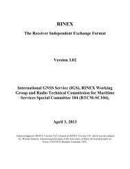
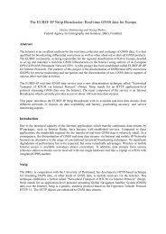
90” 100” 110” 120” 130” 140” 1 W“40”40”EURASIAN PLATE30”30”.20”20”10°10”o“o“-1o”“lo”-20’-20°o“o“-5”-5”-1o’130” 1 35* 140”-lo*Figure 9i’(Top panel) Tectonic setting of Southeast Asia. Open circles indicate regional. sites surveyed by GPS from 1989 to 1993. (Bottom panel) Irian Jaya, Indonesia and 6-station GPS network. GPS velocity vectors and one-sigma error ellipses are indicated forthe 1992-1991 time period, in theITRF91 reference frame which adopts the no-net-rotation(NNR) NUVEL-1 plate motion model of Argus and Gordon (1991).85
the 1992 regional <strong>IGS</strong> and lrian Jaya set) positions and velocities of the Irian Jaya stationswere estimated with respect to ITRF91 and the NNR plate motion model [Argus andGordon; 1990] (Figure 9). This approach allows us to integrate solution files from otherexperiments performed in Indonesia and surrounding areas in a similar straightforwardmatter [Calais et al., 1993]. We have done this, for example, for a series of annualmeasurements across the Java Trench between Christmas Island and Java [Tregoning et al.,1993] and in thq Flores Sea [Genr-ich e? al., 1993],It is clear that with this approach diverse regional experiments taken at different timeperiods with a total of hundreds of stations can be combined in a uniform manner withrespect to ITRF. Solution files can be exchanged between different analysis groups todevelop a coherent picture of tectonic motion over a larger region than any one projectprovides. As long as the underlying physical models are not changed, the solution files canbe analyzed many times as the ITRF improves with time. This is an example of distributedprocessing within the context of a single global <strong>IGS</strong> solution.Scenario 3. There are two regional clusters in California for continuously monitoringcrustal deformation, a southern California array and a northern California array, each of 20stations. Each array does its own regional analysis. The southern California array acquiresthe clean RINEX data from the <strong>IGS</strong> analysis center which are analyzed simultaneously withtwo of the regional stations, producing expanded solution files. In a separate analysis thecomplete set of southern California stations are adjusted together with two stations of thenorthern California array. Thus the southern California analysis center produces two setsof solution files. The northern California analysis center analyzes all data from its ownarray including the overlapping stations analyzed by its southern California counterpart andproduces another set of solution files. All three sets of solution files can then be input to aGLOBK-type program to produce a daily set of coordinate solutions for both southern andCalifornia arrays, with tight constraints applied to the global <strong>IGS</strong> stations..To demonstrate this concept, we refer again to Blewitt et al. [1993] and Bock et al. [ 1993].Both analysis groups were able to determine “absolute” displacements of the PGGAstations using different software, processing algorithms and physical models,demonstrating that distributed processing is feasible. Both groups analyzed the PGGA and<strong>IGS</strong> data simultaneously. However, at some point the number of PGGA and <strong>IGS</strong> stationswill grow to a point that it will not feasible or efficient to continue to do this. Therefore,we test whether we could have obtained the same results using a distributed processingapproach. The Landers data were re-adjusted in two steps using the clean RINEX datafrom the original analysis in which both data sets were adjusted simultaneously [Zhang,1993]. In the first step, the data set that included the entire <strong>IGS</strong> global data set was readjustedsimultaneously with data from two PGGA stations (DS 10 and JPL1 ) generating adaily solution file for the five weeks before and after the earthquakes, In a second step, allthe PGGA data (there were 5 stations operational at that time) were adjusted independentlyand simultaneously, generating a second set of solution files. Both sets of solution fileswere analyzed with the GLOBK software using the same station constraints for the global<strong>IGS</strong> stations as in Bock ef al. [1993]. The coseimic displacements estimated from thisdistributed approach were statistically equivalent as indicated in Figure 10.In another test of distributed processing with the PGGA, L.indqwis?er e? al. [1991]analyzed an unbiased selection of 23 daily sets of measurements spanning 8 months in1990. Aimajor concern was that the CIGNET tracking network at that time wasinstrumented with MiniMac 28 16AT receivers and antennas, and the PGGA with RogueSNR-8 receivers. In an attempt to reduce the effect of different phase center variationsbetween the two types of antennas, the data from each network were reduced separately,and then orbital elements were combined (3 epoch positions, 3 velocities, and 3 solar86
- Page 1 and 2:
●INTERNATIONAL ASSOCIATION OF GEO
- Page 3 and 4:
TABLE OF CONTENTS.FINAL AGENDA . .
- Page 5 and 6:
13:30 NGS14:00 S1014:30 EMR15:00 CO
- Page 7 and 8:
LIST OF PARTICIPANTS:Prof. Gerhard
- Page 10 and 11:
Table 1. Current IGS Analysis Cente
- Page 12 and 13:
The first field identifies the reco
- Page 14 and 15:
Summary InformationThe third produc
- Page 16 and 17:
From Figure 1 we find that there ar
- Page 18:
to define a reference clock in thei
- Page 22 and 23:
SESSION 2(IGS orbit products)
- Page 24 and 25:
1. introductionThe main objectives
- Page 26 and 27:
ecause of the above averaging. This
- Page 28 and 29:
RMS per center (m)o 0 0 0 0 0 oA0Iv
- Page 30:
Scale (ppb)I I I I I 11+-b~ul0Amo&I
- Page 33 and 34:
and NGS. Note that the day to day v
- Page 35 and 36:
Rotation around X-axis (mas)1&0 0o
- Page 37 and 38: discussed in Section 3 are here see
- Page 39 and 40: -----------------------------------
- Page 41 and 42: Residuals in Meters1 1 1 1 1 1 1=%m
- Page 43 and 44: Residuals inMeters11111cnficJJw-o A
- Page 45 and 46: I I I—Residuals in Meters..—.
- Page 47 and 48: 1111ResidualsMeters,—{44
- Page 49 and 50: Residuals in MetersI I I II I I IIc
- Page 51 and 52: Rms in MetersI 1 ! I 1 10 n0 a0n.ff
- Page 53 and 54: IGS- and the COM-sets, but that the
- Page 55 and 56: Table 4.1 N.A. Baseline Repeatabili
- Page 57 and 58: ..Figure 5.1:Clock solutions for FA
- Page 59 and 60: specifically the preanalysis can be
- Page 61 and 62: discussion, a question as to whethe
- Page 63 and 64: SUMMARY OF SESSION 3This Session be
- Page 65 and 66: IGS POSITION PAPER, IGS ANALYSIS CE
- Page 67 and 68: and Earth orientation parameters (E
- Page 69 and 70: LbPIERS and IGSCentral Bureausand D
- Page 71 and 72: @ IGS will develop instructions, an
- Page 73: 2.2 Analysis Center System DesignFi
- Page 76 and 77: applied to the solution in order to
- Page 78 and 79: ..standard deviations. This is conv
- Page 80 and 81: known, the two solutions will be ad
- Page 82 and 83: errors, and can therefore be used a
- Page 84 and 85: International Terrestrial Reference
- Page 86 and 87: Thus, there is the potential of fee
- Page 91 and 92: adiation parameters for each satell
- Page 93 and 94: Bock, Y., R.I. Abbot, C.C. Counselm
- Page 95 and 96: SUMMARY OF SESSION 4This session st
- Page 97 and 98: INTERNATIONAL EARTH ROTATION SERVIC
- Page 99 and 100: x- differences with IERS0.001”I I
- Page 101 and 102: SUMMARY OF SESSION 5In the last ses
- Page 103 and 104: 1) I(X3 PROCESSING/REPORTS/FORMATSS
- Page 105 and 106: IGS should foster and encourage reg
- Page 107 and 108: ..INTERNATIONAL GPS SERVICE FORGEOD
- Page 109 and 110: ortL.s.4
- Page 111 and 112: 1234567a91011121314IsIt17ItIs2C2122
- Page 113 and 114: . Ruth Neilan16S Central BureauJet
- Page 115 and 116: ON1T.>● Jim ZumbergeJet Propulsio
- Page 117: PROPOSED ORGANIZATION OF THE INTERN