
Create successful ePaper yourself
Turn your PDF publications into a flip-book with our unique Google optimized e-Paper software.
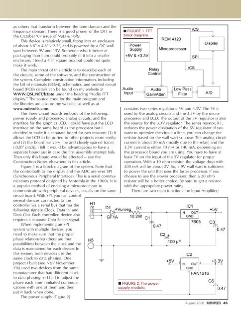
as others that transform between the time domain and thefrequency domain. There is a good primer of the DFT inthe October ‘07 issue of <strong>Nuts</strong> & <strong>Volts</strong>.This device is relatively small, fitting into an enclosureof about 6.8” x 4.8” x 2.5”, and is powered by a DC wallwart between 9V and 15V. Someone who is better atpackaging than I am could probably fit it into a smallerenclosure. I tried a 4.5” square box but could not quitemake it work.The main thrust of this article is to describe each ofthe circuits, some of the software, and the construction ofthe system. Complete construction information, includingthe bill of materials (BOM), schematics, and printed circuitboard (PCB) details can be found on my website atWWW.QSL.NET/k3pto under the heading “Audio FFTdisplay.” The source code for the main program andthe libraries are also on my website, as well as atwww.nutsvolts.com.The three circuit boards embody of the following:power supply and processor; analog circuits; and theinterface for the graphics LCD. I could have put the LCDinterface on the same board as the processor but Idecided to make it a separate board for two reasons: (1) itallows the LCD to be ported to other projects more easily;and (2) the board has very fine and closely spaced traces(.020” pitch). I felt it would be advantageous to have aseparate board just in case the first assembly attempt fails.Then only this board would be affected — see theConstruction Notes elsewhere in this article.Figure 1 is a block diagram of the system. Note thatthe controlpath to the display and the ADC are over SPI(Synchronous Peripheral Interface). This is a serial communicationsprotocol designed by Motorola in the 1960s. It isa popular method of enabling a microprocessor tocommunicate with peripheral devices, usually on the samecircuit board. With SPI, you can controlseveral devices connected to thecontroller via a serial bus that has thefollowing signals: Clock, Data In, andData Out. Each controlled device alsorequires a separate Chip Select signal.When implementing an SPIsystem with multiple devices, youneed to make sure that the properphase relationship (there are fourpossibilities) between the clock and thedata is maintained for each device. Inthis system, both devices use thesame clock to data phasing. Oneproject I built (see N&V November‘06) used two devices from the samemanufacturer that had different clockto data phasing so I had to adjust thephase each time I initiated communicationswith one of them and thenput it back when done.The power supply (Figure 2)■ FIGURE 1. FFTblock diagram.contains two series regulators: 5V and 3.3V. The 5V isused by the analog circuits and the 3.3V by the microprocessorand LCD. The output of the 5V regulator is alsothe source for the 3.3V regulator. The series resistor, R1,reduces the power dissipation of the 5V regulator. If youwant to optimize the circuit a little, you can change theresistor based on the wall wart you use. The analog circuitcurrent is about 20 mA (mostly due to the relay) and the3.3V current is either 70 mA or 140 mA, depending onthe processor board you are using. You have to have atleast 7V on the input of the 5V regulator for properoperation. With a 10 ohm resistor, the voltage drop with200 mA will be about 2V. So, a 9V wall wart is sufficientto power the unit that uses the faster processor. If youchoose to use the slower processor, then a 20 ohmresistor will be a better choice. Be sure to get a resistorwith the appropriate power rating.There are two main functions the Input Amplifier/■ FIGURE 2. The powersupply module.August 2008 45