

FloodStop FS1/4C Operational Sequence (As Leak is ... - Smarthome
FloodStop FS1/4C Operational Sequence (As Leak is ... - Smarthome
FloodStop FS1/4C Operational Sequence (As Leak is ... - Smarthome

Create successful ePaper yourself
Turn your PDF publications into a flip-book with our unique Google optimized e-Paper software.
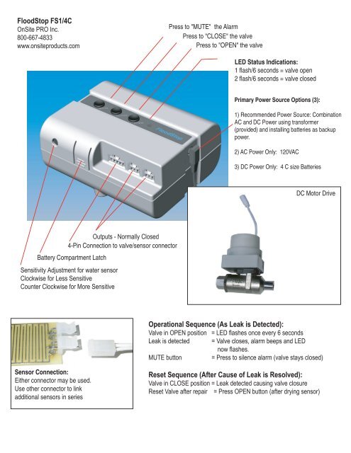
<strong>FloodStop</strong> <strong>FS1</strong>/<strong>4C</strong><br />
OnSite PRO Inc.<br />
800-667-4833<br />
www.onsiteproducts.com<br />
Outputs - Normally Closed<br />
4-Pin Connection to valve/sensor connector<br />
Battery Compartment Latch<br />
Sensitivity Adjustment for water sensor<br />
Clockw<strong>is</strong>e for Less Sensitive<br />
Counter Clockw<strong>is</strong>e for More Sensitive<br />
Sensor Connection:<br />
Either connector may be used.<br />
Use other connector to link<br />
additional sensors in series<br />
Press to "MUTE" the Alarm<br />
Press to "CLOSE" the valve<br />
Press to "OPEN" the valve<br />
LED Status Indications:<br />
1 flash/6 seconds = valve open<br />
2 flash/6 seconds = valve closed<br />
Primary Power Source Options (3):<br />
1) Recommended Power Source: Combination<br />
AC and DC Power using transformer<br />
(provided) and installing batteries as backup<br />
power.<br />
2) AC Power Only: 120VAC<br />
3) DC Power Only: 4 C size Batteries<br />
DC Motor Drive<br />
<strong>Operational</strong> <strong>Sequence</strong> (<strong>As</strong> <strong>Leak</strong> <strong>is</strong> Detected):<br />
Valve in OPEN position = LED flashes once every 6 seconds<br />
<strong>Leak</strong> <strong>is</strong> detected = Valve closes, alarm beeps and LED<br />
now flashes.<br />
MUTE button = Press to silence alarm (valve stays closed)<br />
Reset <strong>Sequence</strong> (After Cause of <strong>Leak</strong> <strong>is</strong> Resolved):<br />
Valve in CLOSE position = <strong>Leak</strong> detected causing valve closure<br />
Reset Valve after repair = Press OPEN button (after drying sensor)
1) Shut off/close the water supply at the ex<strong>is</strong>ting manual shutoff valve.<br />
2) Remove the ex<strong>is</strong>ting supply line from the manual shutoff valve.<br />
3) Connect the <strong>FloodStop</strong> valve downstream of the manual shutoff valve (as close to the manual shutoff valve as possible).<br />
4) Connect the water supply line to the outlet side of the <strong>FloodStop</strong> valve, which leads to the appliance. Use pipe sealant or Teflon tape for NPT/water<br />
heater applications.<br />
Tip: Do not grip the plastic motor drive for leverage when tightening the fitting.<br />
Be sure the water supply line <strong>is</strong> connected to the appliance before going to the next step.<br />
5) Open the manual shutoff valve and check for leaks (tighten as needed till any dripping stops).<br />
6) For use with 120VAC as the “Primary Power Source”, connect the AC wall transformer to the control unit and install 4 C batteries inside the control unit<br />
(batteries will then only serve as a “Secondary Backup Power Source” in case of an electrical power outage).<br />
For use with Batteries Only as the “Primary Power Source” (when a nearby electrical outlet <strong>is</strong> not available), install 4 C batteries inside the control unit.<br />
Replace batteries every year, or when low battery alert indicator <strong>is</strong> activated. Dead batteries will open the contacts on the signal outputs.<br />
7) Connect 4-pin connector to <strong>FloodStop</strong> control unit.<br />
8) Mount the controller with either Velcro provided (for most versatile mount onto appliance or wall),<br />
or screws provided (for most secure mount onto wall).<br />
9) Attach 2-pin connector to <strong>FloodStop</strong> water/leak sensor.<br />
Tip: Wipe up any water that could activate the sensor and <strong>FloodStop</strong> system.<br />
10) Place the water/leak sensor at the base of the appliance.<br />
Tip 1: If sensor <strong>is</strong> located inside a metal pan, place sensor on cloth or paper towel to insulate sensor from metal pan.<br />
Tip 2 : If appliance <strong>is</strong> set inside a pan, consider using 2 sensors and placing one outside the pan and another inside the pan.<br />
Use more sensors for even quicker detection capability. (Part Number ES-01)<br />
11) Plug AC wall transformer into a standard 120 VAC household receptacle.<br />
Tip: If a nearby receptacle <strong>is</strong> not available, a thin 15 foot low voltage “Transformer Extension Wire” may be used instead of a standard electrical<br />
extension cord. Th<strong>is</strong> <strong>is</strong> an optional accessory (Part Number WAE-15).<br />
12) Initiate test cycle = Drop water on sensor to validate functions.<br />
<strong>FloodStop</strong> Installation<br />
Outputs<br />
The two <strong>FloodStop</strong> outputs can be used as a normally closed set of contacts for any device that can<br />
utilize them.<br />
Here are a few items that <strong>FloodStop</strong> can be connected to:<br />
Auto phone dialers<br />
Alarm Systems<br />
X10 Home Automation devices<br />
OnSite PRO, Inc. warrants th<strong>is</strong> product to be free from defects in materials or workmanship, under normal use and service, for one (1) year from the date of original<br />
purchase by the consumer subject to the following conditions: 1) If any defect <strong>is</strong> d<strong>is</strong>covered and the entire unit <strong>is</strong> returned to OnSite PRO Inc. within one (1) year of<br />
the date it was purchased, we will repair or replace it free of charge (except that you are responsible for any expenses you may incur). 2) To obtain warranty service,<br />
ship the entire unit US postage pre-paid, in its original box (or a container adequate to protect the unit from damage in transit) along with the original proof of<br />
purchase (i.e. sales receipt, indicating price paid, date of purchase, location of purchase) to:OnSite PRO Inc. C/O Warranty Service Dept 28896 Mountain View<br />
Lane Trabuco Canyon, CA 92679 (800) 667-4833.<br />
Th<strong>is</strong> warranty does not cover defects in the units resulting from: (a) abuse or m<strong>is</strong>handling of the unit; (b) modification, alteration, repair or service of the unit by<br />
anyone other than OnSite PRO Inc. c) improper or neglect in maintenance. Th<strong>is</strong> warranty does not cover any damages caused by defects in the units, and owner's<br />
use of these products confirms the understanding that these units do not constitute an insurance policy and they are only loss mitigation products used to reduce<br />
the r<strong>is</strong>k of water damage. Any replacement unit will be warranted for the remainder of the warranty period or thirty days from your receipt, whichever <strong>is</strong> longer. Some<br />
states and jur<strong>is</strong>dictions do not allow limitations on duration of an implied warranty or condition, so th<strong>is</strong> limitation may not apply to you.


