

reciprocity and emc measurements - IEEE Electromagnetic ...
reciprocity and emc measurements - IEEE Electromagnetic ...
reciprocity and emc measurements - IEEE Electromagnetic ...

Create successful ePaper yourself
Turn your PDF publications into a flip-book with our unique Google optimized e-Paper software.
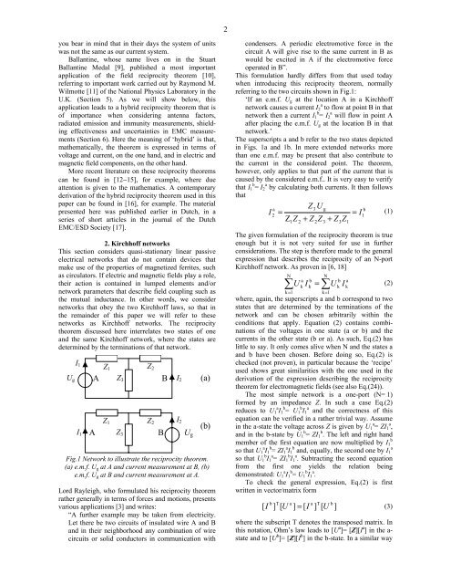
2you bear in mind that in their days the system of unitswas not the same as our current system.Ballantine, whose name lives on in the StuartBallantine Medal [9], published a most importantapplication of the field <strong>reciprocity</strong> theorem [10],referring to important work carried out by Raymond M.Wilmotte [11] of the National Physics Laboratory in theU.K. (Section 5). As we will show below, thisapplication leads to a hybrid <strong>reciprocity</strong> theorem that isof importance when considering antenna factors,radiated emission <strong>and</strong> immunity <strong>measurements</strong>, shieldingeffectiveness <strong>and</strong> uncertainties in EMC <strong>measurements</strong>(Section 6). Here the meaning of ‘hybrid’ is that,mathematically, the theorem is expressed in terms ofvoltage <strong>and</strong> current, on the one h<strong>and</strong>, <strong>and</strong> in electric <strong>and</strong>magnetic field components, on the other h<strong>and</strong>.More recent literature on these <strong>reciprocity</strong> theoremscan be found in [12−15], for example, where dueattention is given to the mathematics. A contemporaryderivation of the hybrid <strong>reciprocity</strong> theorem used in thispaper can be found in [16], for example. The materialpresented here was published earlier in Dutch, in aseries of short articles in the journal of the DutchEMC/ESD Society [17].2. Kirchhoff networksThis section considers quasi-stationary linear passiveelectrical networks that do not contain devices thatmake use of the properties of magnetized ferrites, suchas circulators. If electric <strong>and</strong> magnetic fields play a role,their action is contained in lumped elements <strong>and</strong>/ornetwork parameters that describe field coupling such asthe mutual inductance. In other words, we considernetworks that obey the two Kirchhoff laws, so that inthe remainder of this paper we will refer to thesenetworks as Kirchhoff networks. The <strong>reciprocity</strong>theorem discussed here interrelates two states of one<strong>and</strong> the same Kirchhoff network, where the states aredetermined by the terminations of that network.U gI 1I 1AAZ 1 Z 2Z 3Z 1 Z 2Z 3Fig.1 Network to illustrate the <strong>reciprocity</strong> theorem.(a) e.m.f. U g at A <strong>and</strong> current measurement at B, (b)e.m.f. U g at B <strong>and</strong> current measurement at A.Lord Rayleigh, who formulated his <strong>reciprocity</strong> theoremrather generally in terms of forces <strong>and</strong> motions, presentsvarious applications [3] <strong>and</strong> writes:“A further example may be taken from electricity.Let there be two circuits of insulated wire A <strong>and</strong> B<strong>and</strong> in their neighborhood any combination of wirecircuits or solid conductors in communication withBBI 2I 2U g(a)(b)condensers. A periodic electromotive force in thecircuit A will give rise to the same current in B aswould be excited in A if the electromotive forceoperated in B”.This formulation hardly differs from that used todaywhen introducing this <strong>reciprocity</strong> theorem, normallyreferring to the two circuits shown in Fig.1:‘If an e.m.f. U g at the location A in a Kirchhoffnetwork causes a current I a 2 to flow at point B in thatnetwork then a current I b 1 = I a 2 will flow in point Aafter placing the e.m.f. U g at the location B in thatnetwork.’The superscripts a <strong>and</strong> b refer to the two states depictedin Figs. 1a <strong>and</strong> 1b. In more extended networks morethan one e.m.f. may be present that also contribute tothe current in the considered point. The theorem,however, only applies to that part of the current that iscaused by the considered e.m.f.. It is very easy to verifythat I b 1 = I a 2 by calculating both currents. It then followsthatZ3UagbI (1)2== I1Z Z + Z Z + Z Z12The given formulation of the <strong>reciprocity</strong> theorem is trueenough but it is not very suited for use in furtherconsiderations. The step is therefore made to the generalexpression that describes the <strong>reciprocity</strong> of an N-portKirchhoff network. As proven in [6, 18]NNa b∑UkIk= ∑k=1k=1where, again, the superscripts a <strong>and</strong> b correspond to twostates that are determined by the terminations of thenetwork <strong>and</strong> can be chosen arbitrarily within theconditions that apply. Equation (2) contains combinationsof the voltages in one state (a or b) <strong>and</strong> thecurrents in the other state (b or a). As such, Eq.(2) haslittle to say. It only comes alive when N <strong>and</strong> the states a<strong>and</strong> b have been chosen. Before doing so, Eq.(2) ischecked (not proven), in particular because the ‘recipe’used shows great similarities with the one used in thederivation of the expression describing the <strong>reciprocity</strong>theorem for electromagnetic fields (see also Eq.(24)).The most simple network is a one-port (N= 1)formed by an impedance Z. In such a case Eq.(2)reduces to U a 1 I b 1 = U b 1 I a1 <strong>and</strong> the correctness of thisequation can be verified in a rather trivial way. Assumein the a-state the voltage across Z is given by U a 1 = ZI a 1 ,<strong>and</strong> in the b-state by U b 1 = ZI b 1 . The left <strong>and</strong> right h<strong>and</strong>bmember of the first equation are now multiplied by I 1so that U a 1 I b 1 = ZI a 1 I b a1 <strong>and</strong>, equally, the second one by I 1so that U b 1 I a 1 = ZI b 1 I a 1 . Subtracting the second equationfrom the first one yields the relation beingdemonstrated: U a 1 I b 1 = U b 1 I a 1 .To check the general expression, Eq.(2) is firstwritten in vector/matrix formb T a[ I ] [ U ] = [ Ia(2)(3)where the subscript T denotes the transposed matrix. Inthis notation, Ohm’s law leads to [U a ]= [Z][I a ] in the a-state <strong>and</strong> to [U b ]= [Z][I b ] in the b-state. In a similar way23T] [ UUb]3bkI1ak


