8space antenna factor of one <strong>and</strong> the same log-biconicalantenna, as determined by a UKAS accredited company.We can also conclude from the above that thelinearized model used in documents on EMCmeasurement instrumentation uncertainties [28, 29]cannot be justified. Moreover, the uncertainty in theantenna factor during calibration has little in commonwith the uncertainty in the antenna factor during anactual radiated emission test. In the normalized siteattenuation measurement method the result of the siteattenuation measurement is normalized to the antennafactors, after which the result is compared to atheoretically predicted result. This method is formallyonly correct if it can be demonstrated that the antennafactors used are valid during the conditions of the siteattenuation measurement.As a second example, Fig.8 shows the differencedE max when in the CISPR/A radiated emission roundrobin test (RRT) the field-strength emitted by thebattery operated tightly specified EUT (a rod antennaabove a small ground plane) was firstly measured usinga biconical antenna <strong>and</strong> secondly by using a logbiconicalantenna [30]. When replacing the receivingantenna, care was taken that the remaining part of theset-up was not changed. Only the prescribedmeasurement distance was adjusted by moving thereceiving antenna. In this example, the effect ofintegrating over different parts of the incident fielddistribution comes to the fore very clear. This effect wasalso found in the statistical evaluation of the RRT fieldstrength measurement results using the tightly specifiedEUT [30].dEmax (dB)30−30 100 200 300Frequency (MHz)Fig.8 Measured field strength difference dE max (dB)after a biconical antenna has been replaced by alog-biconical antennaWhen using a log-biconical antenna, the effectivemeasurement distance changes with frequency, <strong>and</strong> ithas sometimes been suggested that is possible to correctfor this effect. From the theory above, it will be clearthat such a correction is only possible if the completeactual incident-field distribution is known <strong>and</strong>accounted for in the correction factor.6.3. Probe calibration in a TEM cellField probes are often calibrated in a TEM-cell. However,the practical use of these probes is generallyoutside such a cell. So the current distribution in the t-state, <strong>and</strong>, consequently, the antenna factor, may bedifferent in cases where the probe is not as close to themetal plates as it is inside the TEM-cell. It seems thatthis aspect was overlooked in [31]. It might therefore beone of the reasons for the limited agreement betweenmeasurement results obtained in the TEM cell <strong>and</strong> thoseobtained outside that cell. In addition, the authors in[31] claim that the <strong>reciprocity</strong> of the TEM cell wasverified experimentally. In that experiment, a firsttransfer function was measured after connecting thesignal generator to the probe acting as transmittingantenna inside the cell <strong>and</strong> the measuring receiver toone of the cell terminals. A second transfer function wasmeasured after reversing the connections, i.e. afterconnecting the generator to the cell terminal <strong>and</strong> themeasuring receiver to the probe. They then concludethat <strong>reciprocity</strong> has been demonstrated as the twotransfer functions differed by less than 1 dB. However,for trivial reasons the TEM cell was a linear passivedevice <strong>and</strong>, hence, was reciprocal. The discussions inSection 3.2 then indicate that the experiment onlydemonstrated that the ratio of the output impedance ofthe generator <strong>and</strong> the input impedance of the measuringreceiver was smaller than 1 dB. If a 50Ω generator <strong>and</strong> a75Ω measuring receiver would have been used, for example,that ratio would most likely have been different<strong>and</strong> the authors would have discovered that their methodneeded an additional consideration.Another application of the <strong>reciprocity</strong> theorem involvinga TEM cell is given in [32].6.4. Radiated immunity, E iIn a radiated immunity test, it is the induced voltage thatmay cause malfunctioning of the EUT. Equation (25)clearly indicates that this voltage is determined by theincident field <strong>and</strong> by the normalized currentdistribution. In this section, aspects of the incident fieldare considered <strong>and</strong> in Section 6.5 aspects of the currentdistribution are considered.The incident field is the field that would be presentin absence of the EUT plus its attached cables acting asan antenna. Consequently, the specified field strength ina radiated immunity test is normally measured <strong>and</strong>adjusted before the placement of the EUT using a smallprobe (negligible interaction with the field source). It isnot correct to measure the specified field strength usinga small probe near the EUT, because that probemeasures the field incident to the probe. The latter fieldmay significantly differ from the incident fieldexperienced by the EUT, as it is the combination of thewanted field <strong>and</strong> the field reflected from the EUT. Thefield incident to the probe might even be almost zero ifthe desired test field <strong>and</strong> the reflected field are in antiphase.After placement of the EUT we need to verify thatthe incident field as such has not changed as a result of apossible strong interaction between the EUT <strong>and</strong> thesource of the field. Such an effect may be observed bycomparing the forward power measured via adirectional coupler, in the connection between thegenerator <strong>and</strong> antenna emitting the test field during thepreviously mentioned field adjustment, with the powermeasured after the placement of the EUT. If the forwardpower has changed, the desired incident field haschanged. A first correction is to adjust the generatoroutput to a level that results in the original forwardpower. However, from the hybrid theorem it followsthat this adjustment does not need to be 100% correct,
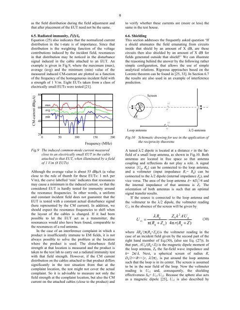
9as the field distribution during the field adjustment <strong>and</strong>that after placement of the EUT need not be the same.6.5. Radiated immunity, I t (l)/I 0Equation (25) also indicates that the normalized currentdistribution in the t-state is of importance. Since thatdistribution is the weighting function of the voltagecontributions induced by the incident field, resonancesin that distribution may be noticed in the disturbancesignal induced in the cable attached to an EUT. Anexample is given in Fig.9, where the maximum (max),average (avg) <strong>and</strong> the minimum (min) value of themeasured induced CM-current are plotted as a functionof the frequency of the homogeneous incident field witha strength of 1 V/m. Eight EUTs taken from a class ofelectrically small EUTs were tested [21].CM-current dB(µA)806040maxavgmin200 50 100 150 200Frequency (MHz)Fig.9 The induced common-mode current measuredclose to an electrically small EUT in the cableattached to that EUT, when illuminated by a fieldof 1 V/m (8 EUTs)Although the average value is about 55 dBµA (a valueclose to the rule of thumb for these EUTs: 1 mA perV/m), the curve labelled ‘min’ indicates that resonancesmay cause a minimum in the induced current, so that theconsidered EUT is hardly tested for immunity aroundthe resonance frequencies. In other words, a uniform<strong>and</strong> constant incident field does not guarantee that theEUT is tested with a constant actual disturbance signal(here represented by the CM current). In addition, weshould expect the resonance frequencies to shift whenthe layout of the cables is changed. If it had beenpossible to let the EUT act as a transmitter, theresonances would also have been found, comparable tothe resonances of a rod antenna.In the case of an interference complaint in which aproduct is insufficiently immune to EM fields, it is notalways possible to solve the problem at the locationwhere the product is used. The disturbance fieldstrength at that location is measured <strong>and</strong> the product istaken to the test lab to carry out a radiated immunity testwith that field strength. However, if the CM currentdistribution on the cables attached to that product differssignificantly in the test situation from that at thecomplaint location, the test might not cover the actualcomplaint. So it is advisable to measure not only thefield strength at the complaint location, but also the CMcurrent on the attached cables (close to the product) <strong>and</strong>to verify whether these currents are (more or less) thesame in the test house.6.6. ShieldingThis section addresses the frequently asked question ‘Ifa shield attenuates the field emanating from circuitsinside that shield by an amount of X dB, are thesecircuits then also shielded by an amount of X dB forfields generated outside that shield?’ We can illustratethe reasoning behind the answer by the following rathersimple configuration, that allows the use of simpleanalytical relations. Rigorous approaches based on theLorentz theorem can be found in [25, 33]. In Section 6.7the results are also used in an example of interferenceprediction.RD aLoop antenna+Screenrλ/2-antennaFig.10 Schematic drawing for use in the application ofthe <strong>reciprocity</strong> theoremsA tuned λ/2 dipole is located at a distance r in the farfieldof a small loop antenna, as shown in Fig.10. Bothantennas are located in free space so that antennacoupling <strong>and</strong> reflections do not play a role. A signalsource {U g , R g } can be connected to the loop antenna,<strong>and</strong> a voltmeter (input impedance R v = R g ) can beconnected to the λ/2 dipole (internal impedance Z a ), <strong>and</strong>vice versa. The area of the loop antenna A= πD a 2 /4 <strong>and</strong>the internal impedance of that antenna is Z l . Theorientation of both antennas is such that an optimalsignal transfer results.If the source is connected to the loop antenna <strong>and</strong>the voltmeter to the λ/2 dipole, the voltmeter readingU v1 in the absence of the screen will be given byUv1=π(2λ RgZ0k AUg⋅R + Z ) 4π r(R + Z)ga(30)where λR g /{π(R g +Z a )}is the voltmeter reading in thecase of an incident field given by the second part of theright h<strong>and</strong> member of Eq.(30), (also see Eq. (27)). Inthat part, AU g /(R g +Z l ) is the magnetic dipole moment ofthe loop antenna, Z 0 the far-field wave impedance <strong>and</strong>k= 2π/λ. Next, a spherical screen of radius R,D a /2