

reciprocity and emc measurements - IEEE Electromagnetic ...
reciprocity and emc measurements - IEEE Electromagnetic ...
reciprocity and emc measurements - IEEE Electromagnetic ...

You also want an ePaper? Increase the reach of your titles
YUMPU automatically turns print PDFs into web optimized ePapers that Google loves.
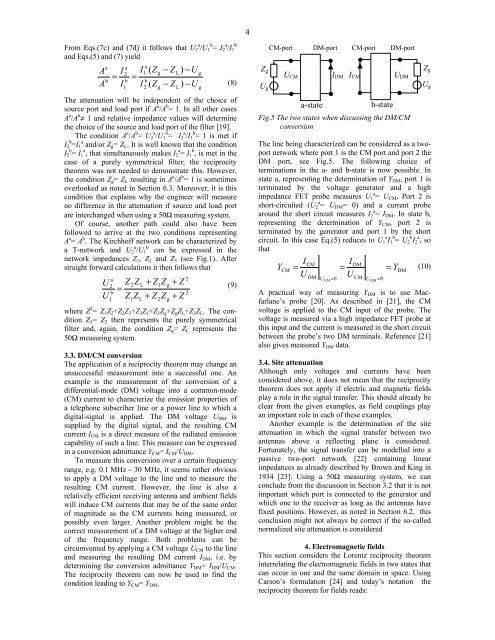
4From Eqs.(7c) <strong>and</strong> (7d) it follows that U 2 a /U 1 b = I 2 a /I 1b<strong>and</strong> Eqs.(5) <strong>and</strong> (7) yieldAAabI=Ia2b1I=Ia1b2( Z( ZThe attenuation will be independent of the choice ofsource port <strong>and</strong> load port if A a /A b = 1. In all other casesA a /A b ≠ 1 <strong>and</strong> relative impedance values will determinethe choice of the source <strong>and</strong> load port of the filter [19].The condition A a /A b = U a 2 /U b 1 = I a 2 /I b 1 = 1 is met ifI b 2 =I a 1 <strong>and</strong>/or Z g = Z L . It is well known that the conditionI b 2 = I a 1 , that simultaneously makes I a 2 = I b 1 , is met in thecase of a purely symmetrical filter; the <strong>reciprocity</strong>theorem was not needed to demonstrate this. However,the condition Z g = Z L resulting in A a /A b = 1 is sometimesoverlooked as noted in Section 6.3. Moreover, it is thiscondition that explains why the engineer will measureno difference in the attenuation if source <strong>and</strong> load portare interchanged when using a 50Ω measuring system.Of course, another path could also have beenfollowed to arrive at the two conditions representingA a = A b . The Kirchhoff network can be characterized bya T-network <strong>and</strong> U a b2 /U 1 can be expressed in thenetwork impedances Z 1 , Z 2 <strong>and</strong> Z 3 (see Fig.1). Afterstraight forward calculations it then follows thatUUa2b1Z2Z=Z Z1LL(8)(9)where Z 2 = Z 1 Z 2 +Z 2 Z 3 +Z 3 Z 1 +Z 3 Z g +Z g Z L +Z 3 Z L . The conditionZ 1 = Z 2 then represents the purely symmetricalfilter <strong>and</strong>, again, the condition Z g = Z L represents the50Ω measuring system.3.3. DM/CM conversionThe application of a <strong>reciprocity</strong> theorem may change anunsuccessful measurement into a successful one. Anexample is the measurement of the conversion of adifferential-mode (DM) voltage into a common-mode(CM) current to characterize the emission properties ofa telephone subscriber line or a power line to which adigital-signal is applied. The DM voltage U DM issupplied by the digital signal, <strong>and</strong> the resulting CMcurrent I CM is a direct measure of the radiated emissioncapability of such a line. This measure can be expressedin a conversion admittance Y CM = I CM /U DM .To measure this conversion over a certain frequencyrange, e.g. 0.1 MHz − 30 MHz, it seems rather obviousto apply a DM voltage to the line <strong>and</strong> to measure theresulting CM current. However, the line is also arelatively efficient receiving antenna <strong>and</strong> ambient fieldswill induce CM currents that may be of the same orderof magnitude as the CM currents being measured, orpossibly even larger. Another problem might be thecorrect measurement of a DM voltage at the higher endof the frequency range. Both problems can becircumvented by applying a CM voltage U CM to the line<strong>and</strong> measuring the resulting DM current I DM , i.e. bydetermining the conversion admittance Y DM = I DM /U CM .The <strong>reciprocity</strong> theorem can now be used to find thecondition leading to Y CM = Y DM .gg+ Z Z+ Z12− Z− ZZggLL+ Z+ Z) −U) −U22ggZ gU gCM-portU CMDM-portI DMa-stateb-stateFig.5 The two states when discussing the DM/CMconversionThe line being characterized can be considered as a twoportnetwork where port 1 is the CM port <strong>and</strong> port 2 theDM port, see Fig.5. The following choice ofterminations in the a- <strong>and</strong> b-state is now possible. Instate a, representing the determination of Y DM , port 1 isterminated by the voltage generator <strong>and</strong> a highimpedance FET probe measures U a 1 = U CM . Port 2 isshort-circuited (U a 2 = U DM = 0) <strong>and</strong> a current probearound the short circuit measures I a 2 = I DM . In state b,representing the determination of Y CM , port 2 isterminated by the generator <strong>and</strong> port 1 by the shortcircuit. In this case Eq.(5) reduces to U a 1 I b 1 = U b 2 I a 2 , sothatICMIDMY(10)CM= = = YDMU UDM UCM= 0CM-portI CMCM U DM = 0DM-portU DMA practical way of measuring Y DM is to use Macfarlane’sprobe [20]. As described in [21], the CMvoltage is applied to the CM input of the probe. Thevoltage is measured via a high impedance FET probe atthis input <strong>and</strong> the current is measured in the short circuitbetween the probe’s two DM terminals. Reference [21]also gives measured Y DM data.3.4. Site attenuationAlthough only voltages <strong>and</strong> currents have beenconsidered above, it does not mean that the <strong>reciprocity</strong>theorem does not apply if electric <strong>and</strong> magnetic fieldsplay a role in the signal transfer. This should already beclear from the given examples, as field couplings playan important role in each of these examples.Another example is the determination of the siteattenuation in which the signal transfer between twoantennas above a reflecting plane is considered.Fortunately, the signal transfer can be modelled into apassive two-port network [22] containing linearimpedances as already described by Brown <strong>and</strong> King in1934 [23]. Using a 50Ω measuring system, we canconclude from the discussion in Section 3.2 that it is notimportant which port is connected to the generator <strong>and</strong>which one to the receiver as long as the antennas havefixed positions. However, as noted in Section 6.2, thisconclusion might not always be correct if the so-callednormalized site attenuation is considered4. <strong>Electromagnetic</strong> fieldsThis section considers the Lorentz <strong>reciprocity</strong> theoreminterrelating the electromagnetic fields in two states thatcan occur in one <strong>and</strong> the same domain in space. UsingCarson’s formulation [24] <strong>and</strong> today’s notation the<strong>reciprocity</strong> theorem for fields reads:Z gU g


