- Page 1 and 2: MVME5100Single Board ComputerInstal
- Page 4: FlammabilityAll Motorola PWBs (prin
- Page 7 and 8: ContentsAbout This ManualSummary of
- Page 9 and 10: IDSEL Routing......................
- Page 11: List of FiguresFigure 1-1. MVME5100
- Page 14 and 15: xivTable D-1. Motorola Computer Gro
- Page 16 and 17: Model NumberMVME5101-216xMVME5110-2
- Page 18 and 19: Summary of ChangesThis is the third
- Page 20 and 21: Appendix C, RAM500 Memory Expansion
- Page 22 and 23: An asterisk (*) following a signal
- Page 24 and 25: 1Hardware Preparation and Installat
- Page 26 and 27: 1Hardware Preparation and Installat
- Page 28 and 29: 1Hardware Preparation and Installat
- Page 30 and 31: 1Hardware Preparation and Installat
- Page 32 and 33: 1Hardware Preparation and Installat
- Page 34 and 35: 1Hardware Preparation and Installat
- Page 36 and 37: 1Hardware Preparation and Installat
- Page 38 and 39: 1Hardware Preparation and Installat
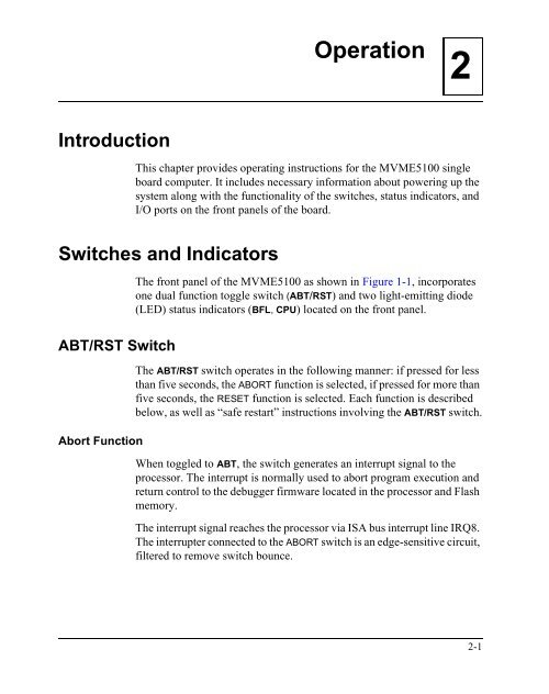
- Page 42 and 43: Operation2Reset FunctionWhen toggle
- Page 44 and 45: Operation2DEBUG PortThe RJ-45 port
- Page 47 and 48: 3PPCBug Firmware3IntroductionThe PP
- Page 49 and 50: Using PPCBugImplementation and Memo
- Page 51 and 52: Using PPCBug8. Delays for 750 milli
- Page 53 and 54: Default SettingsCNFG - Configure Bo
- Page 55 and 56: Default SettingsNote:The bug does n
- Page 57 and 58: Default SettingsPrimary SCSI Data B
- Page 59 and 60: Default SettingsAuto Boot Abort Del
- Page 61 and 62: Default Settings!CautionIf you use
- Page 63 and 64: Default SettingsSerial Startup Code
- Page 65 and 66: Default SettingsThe configured valu
- Page 67 and 68: Default SettingsSpecial PCI Slave I
- Page 69 and 70: Standard CommandsTable 3-1. Debugge
- Page 71 and 72: Standard CommandsTable 3-1. Debugge
- Page 73: Standard CommandsPPCBug Diagnostics
- Page 76 and 77: Functional DescriptionTable 4-1. MV
- Page 78 and 79: Functional DescriptionThe following
- Page 80 and 81: Functional DescriptionApplication N
- Page 82 and 83: Functional DescriptionVMEbus Interf
- Page 85 and 86: 5Pin Assignments5IntroductionThis c
- Page 87 and 88: ConnectorsTable 5-1. Jumper Switche
- Page 89 and 90: ConnectorsTable 5-3. Memory Expansi
- Page 91 and 92:
ConnectorsTable 5-3. Memory Expansi
- Page 93 and 94:
ConnectorsTable 5-4. PCI Expansion
- Page 95 and 96:
ConnectorsPCI Mezzanine Card (PMC)
- Page 97 and 98:
ConnectorsTable 5-6. PMC Slot 1 Con
- Page 99 and 100:
ConnectorsTable 5-7. PMC Slot 1 Con
- Page 101 and 102:
ConnectorsTable 5-8. PMC Slot 1 Con
- Page 103 and 104:
ConnectorsTable 5-9. PMC Slot 2 Con
- Page 105 and 106:
ConnectorsTable 5-11. PMC Slot 2 Co
- Page 107 and 108:
ConnectorsTable 5-12. PMC Slot 2 Co
- Page 109 and 110:
ConnectorsTable 5-13. VMEbus Connec
- Page 111 and 112:
ConnectorsTable 5-14. VMEbus P2 Con
- Page 113 and 114:
ConnectorsTable 5-15. VMEbus Connec
- Page 115:
ConnectorsCOM1 and COM2 Connector P
- Page 118 and 119:
Programming the MVME51xxProcessor B
- Page 120 and 121:
Programming the MVME51xxNotes1. Pro
- Page 122 and 123:
Programming the MVME51xxEstablishin
- Page 124 and 125:
Programming the MVME51xxPCI Arbitra
- Page 126 and 127:
Programming the MVME51xxThe arbitra
- Page 128 and 129:
Programming the MVME51xxThe MVME51x
- Page 130 and 131:
Programming the MVME51xxEndian Issu
- Page 133 and 134:
ASpecificationsAThis appendix lists
- Page 135:
Cooling RequirementsACooling Requir
- Page 138 and 139:
Solving Startup ProblemsBII. There
- Page 140 and 141:
Solving Startup ProblemsBV. The deb
- Page 142 and 143:
Functional DescriptionFunctional De
- Page 144 and 145:
Functional DescriptionCA,BA,WE_L,RA
- Page 146 and 147:
RAM500 Module Installationthat stan
- Page 148 and 149:
RAM500 ConnectorsTable C-3. RAM500
- Page 150 and 151:
RAM500 ConnectorsTable C-3. RAM500
- Page 152 and 153:
RAM500 Programming IssuesTable C-4.
- Page 155 and 156:
DRelated DocumentationDMotorola Com
- Page 157 and 158:
Related DocumentationTable D-2. Man
- Page 159 and 160:
IndexAAbort (interrupt) signal 2-1A
- Page 161 and 162:
MVME510x 1-16MVME510x hardware 1-8M
- Page 163:
features C-1install instructions C-


