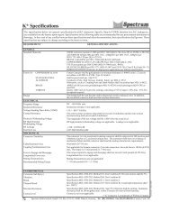
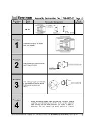
LRL/TRL <strong>Calibration</strong> <strong>Kits</strong>36INTRODUCTION: The LRL (Line Reflective Line), or TRL (Through Reflective Line)<strong>Kits</strong> are using a different approach. To calibrate the system a Short is needed and Throughlinesof two different lengths. The Throughlines are supposed to be ideal. This means that not onlythe impedance of 50 Ohms has to be maintained perfectly. Center Contacts are allowed to berecessed within allowed limits. The Center Contacts of the Throughlines are thereforeavailable in different lengths, taking care of the recessed Contacts at the Test Equipment.Therefore for every Outer Conductor of a Throughline a number of Center Contacts aresupplied, from “0” Recession/Protrusion to max. Protrusion, equaling the max. allowableRecession of the Test Equipment Connector.EQUIPMENT PROVIDED: Each <strong>Calibration</strong> Kit contains as a minimum for the Standard<strong>Calibration</strong> Kit: two Shorts (male and female), two Throughlines each (female/female, male/female, male/male) in different lengths and a Disc for the <strong>Calibration</strong> Characteristics. TheDisc is supplied either for the Vector Network Analyzers of Hewlett Packard, or Wiltron, andis ready to be used. The Professional <strong>Calibration</strong> Kit contains also Interface Gauges, <strong>Calibration</strong>Blocks for the Interface Gauges, and a Torque Wrench.INTERFACE GAUGES: If you are using a Standard <strong>Calibration</strong> Kit and did not purchaseany Connector Interface Gauges, you should not use the longer Center Contact. If you haveInterface Gauges available you should first measure the Recession of the Center Contacts inthe Connectors of the Vector Network Analyzer, or if you are using Test Cables, the Recessionof the Center Contacts in the connectors of those cable assemblies. Then you shouldselect the correct oversize Center Pin, taking care of the Recession at those Connectors.THROUGHLINES: As mentioned earlier, the Throughlines are supplied as outer conductorsand different lengths center conductors. To install the Throughlines, please proceed asfollows:1. Measure the Recession of the Test Connectors.2. Select the appropriate oversize Center Pin (oversize in length).3. Install the Outer Conductor of the Throughline on one of the Test Connectors.4. Insert the appropriate Center Conductor into the Outer Conductor of theThroughline, using the especially designed Insertion Tool.5. Extract the Insertion Tool and connect carefully the second Test Connector.TORQUE WRENCHES: In order to ensure proper mating of the connectors, it is highlyrecommended to always use Torque Wrenches. They do not only ensure proper connection ofthe components but they also help to prevent overtorquing, which may damage or degradethe performance of these expensive ideal components.CONNECTORS SERIES: LRL/TRL <strong>Calibration</strong> <strong>Kits</strong> are availabe in the following connectorseries: 3.5mm, 7mm, K*, N, <strong>SMP</strong> and TNC.PHASE STABLE CABLE ASSEMBLIES: <strong>Spectrum</strong> <strong>Elektrotechnik</strong> <strong>GmbH</strong> offers a seriesof Phase Stable Assemblies, fitted at one side with the appropriate NMD connector for directconnection with the Vector Network Analyzers of Hewlett Packard and Wiltron, and with2.4mm, 3.5mm, K*, <strong>SMP</strong>, N, TNC, etc. at the other end of the Assembly.<strong>Spectrum</strong> <strong>Elektrotechnik</strong> <strong>GmbH</strong> P.O. Box 45 05 33, 80905 Munich, Germany Tel. (89) 354 804-0, Fax (89) 354 804-90 (Country Code: 49)* 'K' Connector is a trademark of Wiltron Company.trefli.pm6
LRL/TRL <strong>Calibration</strong> <strong>Kits</strong>trefli.pm6<strong>Spectrum</strong> <strong>Elektrotechnik</strong> <strong>GmbH</strong> P.O. Box 45 05 33, 80905 Munich, Germany Tel. (89) 354 804-0, Fax (89) 354 804-90 (Country Code: 49)37