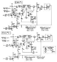
CIRCUIT DIAGRAM (MAIN)
CIRCUIT DIAGRAM (MAIN)
CIRCUIT DIAGRAM (MAIN)
- No tags were found...

Create successful ePaper yourself
Turn your PDF publications into a flip-book with our unique Google optimized e-Paper software.
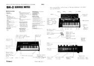
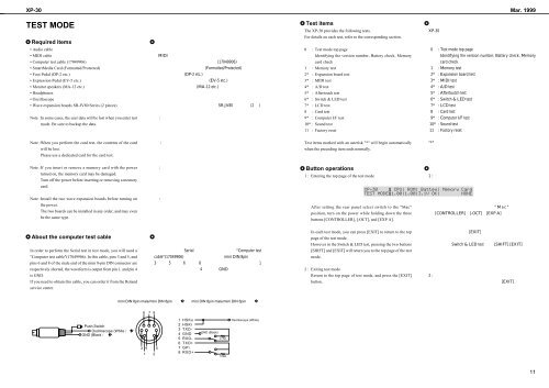
XP-30 Mar. 1999TEST MODERequired items• Audio cable• MIDI cable• Computer test cable (17049906)• SmartMedia Card (Formatted/Protected)• Foot Pedal (DP-2 etc.)• Expression Pedal (EV-5 etc.)• Monitor speakers (MA-12 etc.)• Headphones• Oscilloscope• Wave expansion boards SR-JV80 Series (2 pieces)Note :In some cases, the user data will be lost when you enter testmode. Be sure to backup the data. Test itemsThe XP-30 provides the following tests.For details on each test, refer to the corresponding section.0 : Test mode top pageIdentifying the version number, Battery check, Memorycard check1 : Memory test2* : Expansion board test3* : MIDI test4* : A/D test5* : Aftertouch test6* : Switch & LED test7* : LCD test8 : Card test9* : Computer I/F test10* : Sound test11 : Factory reset Note :When you perform the card test, the contents of the cardwill be lost.Please use a dedicated card for the card test.Test items marked with an asterisk "*" will begin automaticallywhen the preceding item ends normally.Note :If you insert or remove a memory card with the powerturned on, the memory card may be damaged.Turn off the power before inserting or removing a memorycard. Button operations1 : Entering the top page of the test mode Note :Install the two wave expansion boards before turning onthe power.The two boards can be installed in any order, and may evenbe the same type. After setting the rear panel select switch to the "Mac"position, turn on the power while holding down the threebuttons [CONTROLLER], [-OCT], and [EXP A]. About the computer test cableIn order to perform the Serial test in test mode, you will need a"Computer test cable"(17049906). In this cable, pins 3 and 5, andpins 6 and 8 of the male end of the mini 8-pin DIN connector arerespectively shorted, the waveform is output from pin 1, and pin 4is GND.If you need to obtain this cable, you can order it from the Rolandservice center.In each test mode, you can press [EXIT] to return to the toppage of the test mode.However in the Switch & LED test, pressing the two buttons[SHIFT] and [EXIT] will return you to the top page of the testmode.2 : Exiting test modeReturn to the top page of test mode, and press the [EXIT]button. mini DIN 8pin male/mini DIN 8pin mini DIN 8pin male/mini DIN 8pin 6 7 8Push SwitchOscilloscope (White )GND (Black )3 4 51 21 HSKo2 HSKi3 TXD-4 GND5 RXD-6 TXD+7 GPi8 RXD+GND (Black)27kΩ10kΩOscilloscope (White)11