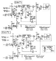
CIRCUIT DIAGRAM (MAIN)
CIRCUIT DIAGRAM (MAIN)
CIRCUIT DIAGRAM (MAIN)
- No tags were found...

You also want an ePaper? Increase the reach of your titles
YUMPU automatically turns print PDFs into web optimized ePapers that Google loves.
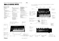
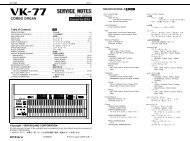
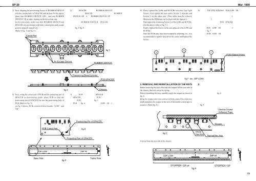
XP-30 Mar. 19992) Next, aligning the positioning bosses of RUBBER SWITCH2) SPACERRUBBER SWITCH4) Then, tighten the LOW and HI PCBs with the Tap Tight4) TAP TITE SCREWSPCB LOWHIwith the circular holes of SPACER, and as done for the spacer,SPACERRUBBERScrews. First tighten the near-center Screws 1, then the endplace four RUBBER SWITCH 12PL, and one RUBBERSWITCH 12P4RUBBER SWITCH 13PScrews 2 on the other side. (This order must be followd.1SWITCH 13P in order, starting on the lower tone side.Ohterwise the PCBs may not be flush with the Spacers.)2In this procedure, make sure that RUBBER SWITCH andRUBBER SWITCHSPACERThen tighten the remaining Screws 3 of the LOW and HI PCBs.PCBSPACERSPACER are positioned with their cutout parts and ascape(For the above, refer to Fig. 7.)grooves aligned, respectively.fig. 3 fig. 4Finally, tighten the Screws in the area adjacent to the LOW andPCBLOWHI3(Refer to fig. 3 and fig. 4.)HI PCBs.fig. 7Cutout PartSince the PCBs may have been warped by soldering, etc., it isrecommended to gently hole down the center and tighten thePCBLOWHIScrews.fig.3231PCB Adjacent AreaAir-Escape GrooveRUBBER SWITCHPosisioning Boss(6 points)PCB SPACERfig.7 (ex. 32P LOW)2. REMOVAL AND REINSTALLATION OF THE KEYS2. fig.4ChassisBefore removing the keys, first take the stopper off the rear side ofthe chassis, then take away the spring.3) Next, using the cutout part of PCB and the projecting part ofSPACER as positioning guide, place PCB so that thepositioning pin of SPACER fits into the positioning hole ofPCB. (Refer to fig. 5)As fig. 6 shows, PCBs consist of three boards, "LOW" and3) PCBSPACERSPACER PCBPCBfig. 5PCBfig. 6LOWHI2When reinstalling the keys, carefully apply the stopper as shown infig. 8.Bring the stopper into closs contact with the ends of the white keyshafts and press the stopper in the area of the double-coated tape tosecure it. (Refer fig. 8.)fig. 8fig. 8"HI".Double-CoatedAdhesive TapePositioning Pin of SPACERStopperPCB Cutout Partfig.5Projecting Part of SPACERfig.8Viewed from the rear side of the chassis.SharpKey AxisNormal Key Axis32P LOW29P HIBass Sidefig.6Treble Side32P LOW29P HISTOPPER 12P x4fig.9STOPPER 13P19