XP-30 Mar. 1999Press and then release the foot pedal.7 : LCD test Verify that "OK" is displayed for "Hld."If "OK" is not displayed for "Hld,"check JK4 on the mainboard.When "OK" is displayed for all items, you will automaticallyPress the [ENTER] button.proceed to the next test.Move the encoder.5 : Aftertouch test Verify that nothing is displayed in the LCD.If something shows in the LCD,check IC3 and IC12 on themain board.Press the [ENTER] button.There are three key ranges.Key:L : C2 - E3Move the encoder.Key:M : F3 - E5Verify that all dots of the LCD are displayed, whether theKey:H : F5 - C7contrast changes, whether any dots are missing, and that allIn each of the three key ranges, press the keyboard deeply anddots darken evenly.then release it.If there is any abnormality in the LCD,check IC3 and IC12 onthe main board.Verify that "OK" is displayed for "Key:L," "Key:M," andIf there is a problem with the encoder,check IC3 on the main"Key:H."board, and EN1 on the panel board.If "OK" is not displayed,check IC10 and CN2 on the main board, or the keyboard.If there are no problems, press [ENTER].You will proceed to the next test.When "OK" is displayed for all items, you will automaticallyproceed to the next test.8 : Memory card test6 : Switch & LED testVerify that the display indicates "OK."If the display does not indicate "OK,"check IC3, IC16, IC19,Verify that all LED's light.IC13, and RA48 on the main board.If not all LED's light, checkIC3, IC43, IC44, RA52, Q15-27, and CN10-12 on the mainboard,and LED, CN1, CN3, and CN4 on the panel board.When the "OK" display appears, you will automaticallyproceed to the next test.Press the panel buttons in any order.At this time, do not press multiple buttons simultaneously.Note: When you perform the card test, the content of the card will be lost.Verify that the name of the button you pressed is displayed,Please use a dedicated card for the card test.and that the LED goes dark (if the button has an LED).Of the name of the button you pressed is not displayed, checkIC3, IC42, RA52, and CN10-12 on the main board,and theswitches, CN1, CN3, and CN4 on the panel board.If the LED's do not go dark, check IC3, IC43, IC44, RA52, Q15-27, and CN10-12 on the mainboard,and LED's, CN1, CN3, and CN4 on the panel board.After you press all buttons, you will automatically advance tothe next test.14
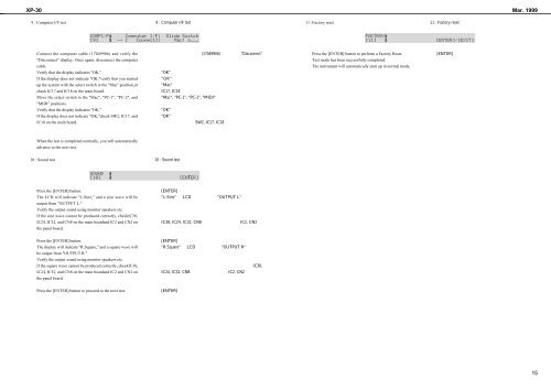
XP-30 Mar. 19999 : Computer I/F test 11 :Factory resetConnect the computer cable (17049906) and verify thePress the [ENTER] button to perform a Factory Reset."Disconnect" display. Once again, disconnect the computerTest mode has been successfully completed.cable.The instrument will automatically start up in normal mode.Verify that the display indicates "OK."If the display does not indicate "OK,"verify that you started up the system with the select switch in the "Mac" position,orcheck IC17 and IC18 on the main board.Move the select switch to the "Mac", "PC-1", "PC-2", and"MIDI" positions.Verify that the display indicates "OK."If the display does not indicate "OK,"check SW2, IC17, andIC18 on the main board.When the test is completed normally, you will automaticallyadvance to the next test.10 : Sound testPress the [ENTER] button.The LCD will indicate "L:Sine," and a sine wave will beoutput from "OUTPUT L."Verify the output sound using monitor speakers etc.If the sine wave cannot be produced correctly, checkIC38,IC24, IC32, and CN8 on the main boardand IC2 and CN2 onthe panel board.Press the [ENTER] button.The display will indicate "R:Square," and a square wave willbe output from "OUTPUT R."Verify the output sound using monitor speakers etc.If the square wave cannot be produced correctly, checkIC38,IC24, IC32, and CN8 on the main boardand IC2 and CN2 onthe panel board.Press the [ENTER] button to proceed to the next test.15