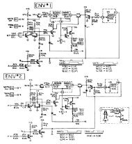
CIRCUIT DIAGRAM (MAIN)
CIRCUIT DIAGRAM (MAIN)
CIRCUIT DIAGRAM (MAIN)
- No tags were found...

You also want an ePaper? Increase the reach of your titles
YUMPU automatically turns print PDFs into web optimized ePapers that Google loves.
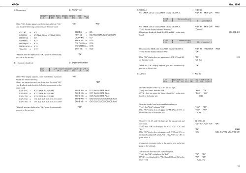
XP-30 Mar. 19991 : Memory test 3 : MIDI testUse a MIDI cable to connect MIDI IN and MIDI OUT.If the "NG" display appears, verify the item which is "NG,"and check the following components on the main board.Use a MIDI cable to connect MIDI IN and MIDI OUT.Verify that the display indicates "Connect."CPU NG → IC5 → If this is not displayed, check IC4, IC8, and JK1 on the mainROM NG → IC1(Mask ROM), IC7(Flash ROM) → board.DRAM NG → IC9SRAM NG → IC14DSP DspNG → IC24DSPRAMNG→ IC35Wave NG → IC22 → → → → → Disconnect the MIDI cable from MIDI IN and MIDI OUT.Verify that the display indicates "OK."When all items are displayed as "OK," you will automaticallyproceed to the next test.If the "OK" display does not appear,check IC4, IC8, and JK1on the main board.2 : Expansion board test When the "OK" display appears, you will automaticallyproceed to the next test.4 : A/D test If the "NG" display appears, verify that the two expansionboards are inserted correctly.If they are inserted correctly, verify the item for which "NG"was displayed, and check the following components on themain board.Move the bender all the way to the left and right.EXP-A NG → IC23, RA38, RA39, RA46EXP-B NG → IC27, RA38, RA39, RA46EXP-C NG → IC28, RA38, RA39, RA46EXP-D NG → CN6, IC20, IC25, IC26, IC30, IC31, RA45EXP-E NG → CN7, IC20, IC25, IC26, IC30, IC31, RA45 → → → → → Verify that "Bend" indicates "OK."If "OK" does not appear for "Bend,"check IC45 on the mainboard, or the bender unit.Move the bender lever in the modulation direction.When all items are displayed as "OK," you will automaticallyVerify that "Mod" indicates "OK."proceed to the next test.If the "OK" display does not appear for "Mod,"check IC45 onthe main board, or the bender unit.Move C1, C2, C3, and C4 sliders all the way upward anddownward.Verify that "OK" is displayed for "C1", "C2", "C3", and"C4."If the "OK" display does not appear,check CN10 and IC46 onthe main board,and CN1, IC1, VR1, VR2, VR3, and VR4 onpanel board A.Connect an expression pedal to the control jack, and a footpedal to the hold jack.Advance and then return the expression pedal.Verify that "OK" is displayed for "Pdl."If "OK" is not displayed for "Pdl,"check IC10 and JK2 on themain board.13