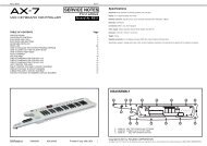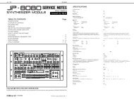
CIRCUIT DIAGRAM (MAIN)
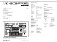
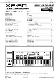
CIRCUIT DIAGRAM (MAIN)
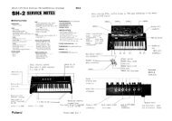
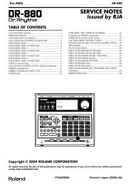
CIRCUIT DIAGRAM (MAIN)
- No tags were found...

Create successful ePaper yourself
Turn your PDF publications into a flip-book with our unique Google optimized e-Paper software.
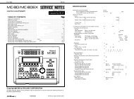
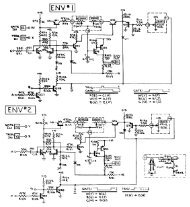
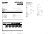
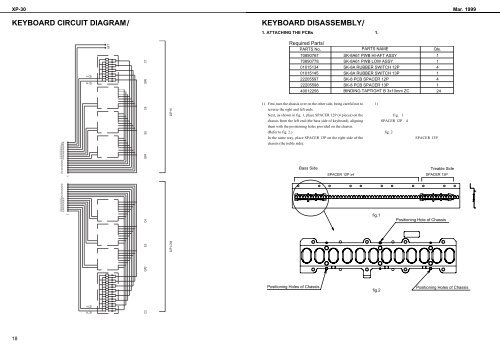
XP-30 Mar. 1999KEYBOARD <strong>CIRCUIT</strong> <strong>DIAGRAM</strong>KEYBOARD DISASSEMBLY1. ATTACHING THE PCBs1. AFTAFTS.M.7P.M.7S.M.6P.M.6S.M.5P.M.5S.M.4P.M.4T7T6T5T4T3T2T1T0T7T6T5T4T3T2T1T0S.M.3P.M.3S.M.2P.M.2S.M.1P.M.1S.M.0P.M.011M SM PM SM P AFTC2G#2E3C4G#4E5C6G#6C729P HI32P LOWRequired Parts/PARTS No, PARTS NAME Qty.708907677089077801015134010151452220559722205598400122561) First, turn the chassis over on the other side, being careful not toreverse the right and left ends.Next, as shown in fig. 1, place SPACER 12P (4 pieces) on thechassis from the left end (the bass side of keyboard), aligningthem with the posisioning holes provided on the chassis.(Refer to fig. 2.)In the same way, place SPACER 13P on the right side of thechassis (the treble side).Bass SidePositioning Holes of ChassisSPACER 12P x4SK-8A61 PWB HI-AFT ASSYSK-8A61 PWB LOW ASSYSK-8A RUBBER SWITCH 12PSK-8A RUBBER SWITCH 13PSK-8 PCB SPACER 12PSK-8 PCB SPACER 13PBINDING TAPTIGHT B 3x10mm ZCfig.1fig.2114141241) fig. 1SPACER 12P4fig. 2SPACER 13PTreable SideSPACER 13PPositioning Hole of ChassisPositioning Holes of Chassis18