cb sx operating manual
cb sx operating manual
cb sx operating manual

Create successful ePaper yourself
Turn your PDF publications into a flip-book with our unique Google optimized e-Paper software.
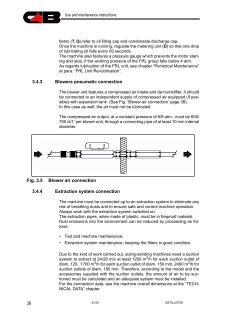
Use and maintenance instructionsItems (T, Q) refer to oil filling cap and condensate discharge cap.Once the machine is running, regulate the metering unit (D) so that one dropof lubricating oil falls every 60 seconds.The machine also features a pressure gauge which prevents the motor startingand stop, if the working pressure of the FRL group falls below 4 atm.As regards lubrication of the FRL unit, see chapter “Periodical Maintenance”at para. “FRL Unit Re-lubrication”.3.4.3 Blowers pneumatic connectionThe blower unit features a compressed air intake and de-humidifier. It shouldbe connected to an independent supply of compressed air equipped (if possible)with expansion tank (See Fig. ’Blower air connection’ page 38).In this case as well, the air must not be lubricated.The compressed air output, at a constant pressure of 6/8 atm., must be 600/700 nl/1’ per blower unit, through a connecting pipe of at least 10 mm internaldiameter.Fig. 3.5Blower air connection3.4.4 Extraction system connectionThe machine must be connected up to an extraction system to eliminate anyrisk of breathing dusts and to ensure safe and correct machine operation.Always work with the extraction system switched on.The extraction pipes, when made of plastic, must be in fireproof material.Dust emissions into the environment can be reduced by proceeding as follows:• Tool and machine maintenance;• Extraction system maintenance, keeping the filters in good condition.Due to the kind of work carried out, sizing-sanding machines need a suctionsystem to extract at 24/28 m/s at least 1200 m 3 /h for each suction outlet ofdiam. 120, 1700 m 3 /h for each suction outlet of diam. 150 mm, 2400 m 3 /h forsuction outlets of diam. 180 mm. Therefore, according to the model and theaccessories supplied with the suction outlets, the amount of air to be suctionedmust be calculated and an adequate system must be installed.For the connection data, see the machine overall dimensions at the “TECH-NICAL DATA” chapter.388/1/04 INSTALLATION