
Create successful ePaper yourself
Turn your PDF publications into a flip-book with our unique Google optimized e-Paper software.
�<br />
�<br />
�<br />
�<br />
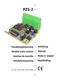
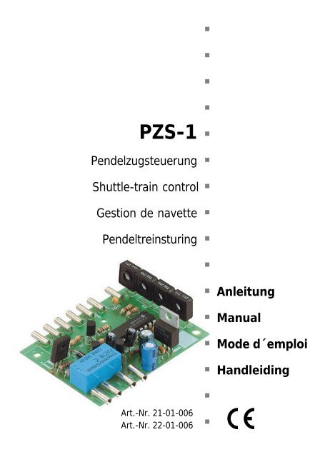
<strong>PZS</strong>-1 �<br />
Pendelzugsteuerung �<br />
Shuttle-train control �<br />
Gestion de navette �<br />
Pendeltreinsturing �<br />
Art.-Nr. 21-01-006<br />
Art.-Nr. 22-01-006<br />
�<br />
� Anleitung<br />
� Manual<br />
� Mode d´emploi<br />
� Handleiding<br />
�<br />
�
© 05/2001 <strong>Tams</strong> Elektronik GmbH<br />
Alle Rechte, insbesondere das Recht der<br />
Vervielfältigung und Verbreitung sowie der<br />
Übersetzung vorbehalten. Vervielfältigungen<br />
und Reproduktionen in jeglicher Form<br />
bedürfen der schriftlichen Genehmigung<br />
durch die <strong>Tams</strong> Elektronik GmbH.<br />
Technische Änderungen vorbehalten.<br />
© 05/2001 <strong>Tams</strong> Elektronik GmbH<br />
All rights reserved. No part of this<br />
publication may be reproduced or<br />
transmitted in any form or by any means,<br />
electronic or mechanical, including<br />
photocopying, without prior permission in<br />
writing from <strong>Tams</strong> Elektronik GmbH.<br />
Subject to technical modification.<br />
© 05/2001 <strong>Tams</strong> Elektronik GmbH<br />
Tout droits réservés, en particulier les droits<br />
de reproduction et de diffusion ainsi que le<br />
traduction. Toute duplication ou<br />
reproduction sous quelque forme que ce soit<br />
nécessite l´accord écrit de la societé <strong>Tams</strong><br />
Elektronik GmbH.<br />
Sous réserve de modifications techniques.<br />
© 05/2001 <strong>Tams</strong> Elektronik GmbH<br />
Alle rechten voorbehouden. Niets uit deze<br />
publicatie mag worden vermenigvuldigd<br />
opgeslagen of openbaar gemaakt, zonder<br />
voorafgaande schriftelijke toestemming van<br />
<strong>Tams</strong> Elektronik GmbH.<br />
Technische wijzigingen voorbehouden.<br />
�<br />
�<br />
�<br />
� Deutsch 3<br />
� English 24<br />
� Français 41<br />
� Nederlands 63<br />
�<br />
�<br />
�<br />
�<br />
�<br />
�<br />
�<br />
�<br />
�<br />
�<br />
�<br />
�<br />
�
English<br />
Table of contents<br />
How to use this manual 25<br />
Intended use 25<br />
Safety instructions 25<br />
EMC declaration 27<br />
Operation overview 28<br />
Checking the package contents 30<br />
Technical specifications 30<br />
Choosing a power supply 31<br />
Required tools and consumables 31<br />
Safe and correct soldering 31<br />
Assembling the kit 33<br />
Performing a visual check 35<br />
Functional test 36<br />
Connecting the shuttle-train control 38<br />
Setting the shuttle-train control 39<br />
FAQ 40<br />
Manufacturer's note 41<br />
Certification 41<br />
Conditional warranty 41<br />
Parts list I.1<br />
Printed Circuit Board (PCB) layout (Fig.1) I.2<br />
Circuit Diagram (Fig. 3) II<br />
Connections (Fig. 4) III<br />
(Pages I to III in the centre of this handbook are removeable)<br />
Page 24
How to use this manual<br />
English<br />
If you have no specialist technical training, this manual gives step-bystep<br />
instructions for safe and correct assembly of the kit or fitting of<br />
ready-built modules, and operation. Before you start, we advise you to<br />
read the whole manual, particularly the chapter on safety instructions<br />
and the FAQ chapter. You will then know where to take care and how<br />
to prevent mistakes which take a lot of effort to correct.<br />
Keep this manual safely so that you can solve problems in the future. If<br />
you pass the kit on to another person, please pass on the manual with it.<br />
Intended use<br />
! Caution:<br />
Integrated circuits are very sensitive to static electricity. Do not touch<br />
components without first discharging yourself. Touching a radiator or<br />
other grounded metal part will discharge you.<br />
The kit or the ready-built module can be assembled or fitted using this<br />
manual. The ready-built module is designed for use in model railways to<br />
control realistic shuttle-train traffic between two terminus stations.<br />
The kit and the ready-built module are not suitable for children under<br />
the age of 14.<br />
Reading, understanding and following the instructions in this manual<br />
are mandatory for the user.<br />
Any other use of the kit is inappropriate and invalidates any guarantees.<br />
Safety instructions<br />
Mechanical hazards<br />
Cut wires can have sharp ends and can cause serious injuries. Watch<br />
out for sharp edges when you pick up the PCB.<br />
Page 25
English<br />
Visibly damaged parts can cause unpredictable danger. Do not use<br />
damaged parts: recycle and replace them with new ones.<br />
Electrical hazards<br />
� Do not touch powered, live components.<br />
� Do not touch conducting components which are live due to<br />
malfunction.<br />
� Avoid short circuits.<br />
� Do not connect the circuit to a higher voltage than designed.<br />
� Impermissibly high humidity.<br />
� Condensation building up can cause serious injury due to electrical<br />
shock.<br />
Take the following precautions to prevent this danger:<br />
� Never perform wiring on a powered module.<br />
� Only use low power for this module as described in this manual and<br />
only use certified transformers.<br />
� Connect transformers and soldering stations only in approved mains<br />
sockets installed by an authorised electrician.<br />
� Observe cable diameter requirements.<br />
� Assembling the kit should only be done in closed, clean, dry rooms.<br />
Beware of humidity.<br />
� If the humidity in the room is too high, please do not start working<br />
until after a minimum of 2 hours of acclimatisation.<br />
� Use only original spare parts if you have to repair the kit or the<br />
ready-built module.<br />
Fire risk<br />
Touching flammable material with a hot soldering iron can cause lifethreatening<br />
fire, burns and toxic smoke. Connect your soldering iron or<br />
soldering station only when actually needed. Use the correct soldering<br />
Page 26
English<br />
iron or station and never leave a hot soldering iron or station<br />
unattended.<br />
Thermal danger<br />
A hot soldering iron or liquid solder accidentally touching your skin can<br />
cause skin burns. As a precaution:<br />
� use a heat-resistant mat during soldering,<br />
� always put the hot soldering iron in the soldering iron stand,<br />
� point the soldering iron tip carefully when soldering, and<br />
� remove liquid solder with a thick wet rag or wet sponge.<br />
Dangerous environments<br />
A working area that is too small or cramped is unsuitable and can cause<br />
accidents, fires and injury. Prevent this by working in a clean, dry room<br />
with enough freedom of movement.<br />
Other dangers<br />
Children can cause any of the accidents mentioned above because they<br />
are inattentive and not responsible enough. Children under the age of<br />
14 should not be allowed to work with this kit or the ready-built<br />
module.<br />
Little children can swallow small components with sharp edges. Life<br />
threatening! Do not allow components to reach small children.<br />
In schools, training centres, clubs and workshops, assembly must be<br />
supervised by qualified personnel.<br />
In industrial institutions, health and safety regulations applying to<br />
electronic work must be adhered to.<br />
EMC declaration<br />
This product is developed in accordance with the European standards<br />
EN 55014 and EN 50082-1, tested corresponding to the EC - directive<br />
Page 27
English<br />
89/336/EWG (EMVG of 09/11/1992, electromagnetic tolerance) and<br />
meets legal requirements.<br />
To guarantee the electromagnetic tolerance you must take the<br />
following precautions:<br />
� Connect the transformer only to an approved mains socket installed<br />
by an authorised electrician.<br />
� Make no changes to the original parts and accurately follow the<br />
instructions, circuit diagram and PCB layout included with this<br />
manual.<br />
� Use only original spare parts if you have to repair the kit or the<br />
ready-built module.<br />
Operation overview<br />
When power is switched on, the shuttle-train service between the home<br />
station (station 1) and the target station (station 2) starts. There are 4<br />
phases between the two stations: acceleration, normal speed, braking,<br />
and stop. The duration of the time-dependent phases is set at trimpots.<br />
The length of the acceleration and braking phases is time-dependent.<br />
Differing acceleration and braking phases can be set for the two<br />
terminus stations, but for each station the length of the acceleration<br />
and the braking phases are equal.<br />
The braking phase starts when the train passes a braking contact. It<br />
stops when the set braking phase finishes or it passes the stop contact.<br />
At the terminus stations the trains stops for an adjustable time, equal<br />
for both stations.<br />
It is possible to insert reduced speed level during normal speed. It<br />
starts when a contact is passed.<br />
During the normal speed (but not during acceleration, braking, or<br />
reduced speed level) a double flashlight can be switched on or off by<br />
passing a contact. The double flashlight switches off when the braking<br />
phase begins.<br />
Page 28
Function of the five inputs<br />
English<br />
Input "BREMS": An earth impulse at this input initiates the braking<br />
phase for station 1 or 2, depending on the direction of travel. The<br />
braking phase can only start after normal speed of at least 2 seconds.<br />
Input "STOP": An earth impulse at this input immediately ends the<br />
braking phase and the train stops. This function can only be performed<br />
during the braking phase!<br />
Input "LANGSAM": An earth impulse at this input gradually reduces the<br />
speed of the train, e.g. to pass a set of points or a building-site with<br />
reduced speed. After the length of time set at the trim-pot, the speed<br />
gradually increases to normal speed. The reduced speed level<br />
automatically finishes at the beginning of the braking phase and does<br />
not work in acceleration and braking phases.<br />
Input "HEIMAT": As long as the contact is open, the train shuttles<br />
between the two terminus stations. When the contact is connected to<br />
earth, the train stops on reaching the home station. When the contact<br />
is opened again, the shuttle-train service starts again.<br />
Input "BLINK": An earth impulse at this input initiates a double<br />
flashlight (e.g. for a level crossing). After at least 2 seconds the double<br />
flashlight can be switched off by a second earth impulse or by starting<br />
the braking phase. After 2 more seconds it can be switched on by a<br />
new earth impulse. The double flashlight cannot be activated during the<br />
acceleration, braking, or during reduced speed level.<br />
Function of the circuit<br />
The following information is for experienced electronics users and is not<br />
required for the safe and correct assembly and fitting of the module.<br />
A program saved on to the micro-controller controls the different<br />
phases of the shuttle-train service. Accelerating and braking generate a<br />
PWM (pulse-width modulation), which is converted into a direct voltage<br />
by the RC-combinations R2/C5 and R1/C6. When accelerating or<br />
braking the change in the PWM generates a gradually rising or falling<br />
Page 29
English<br />
voltage. The PWM is finished when the highest speed is reached or<br />
when the train stops.<br />
The voltage controls a Darlington circuit composed of the transistors Q1<br />
and Q5. The transistor Q5 supplies the voltage to the tracks.<br />
If the running train is consuming too much current (e.g. at a short<br />
circuit), the voltage drops at the load resistor R9, which controls the<br />
transistor Q3. This transistor acts as a protection circuit for the<br />
Darlington circuit to be less modulated.<br />
After every course of the shuttle-train, the voltage of the trim-pots is<br />
read again from the micro-controller.<br />
Checking the package contents<br />
Check the contents of the package for completeness:<br />
� 1 kit, containing the components listed in the parts list and 1 PCB or<br />
� 1 ready-built module and 1 diode 1N4002 (or similar),<br />
� 1 manual.<br />
Technical specifications<br />
Supply voltage 8 -16 Volt DC<br />
Current consumption<br />
(without connected loads) 20 mA<br />
Max. current per output BL-1 / BL-2 20 mA<br />
Max. current per output traffic<br />
without heat sink 400 mA<br />
with heat sink (not included) 1000 mA<br />
Protected to IP 00<br />
Ambient temperature in use 0 - + 60° C<br />
Ambient temperature in storage -10 - + 80° C<br />
Comparative humidity allowed max. 85 %<br />
Dimensions ca. 64 x 48mm<br />
Weight ca. 25 g<br />
Page 30
Choosing a power supply<br />
!<br />
English<br />
The module is designed for connection to a model railway power<br />
source, i.e. 8-16 Volt direct (d.c.) voltage. Direct connection to a control<br />
transformer is possible.<br />
Required tools and consumables<br />
Make sure you have the following tools, equipment and materials ready<br />
for use:<br />
� a heat-resistant mat<br />
� a soldering iron stand with tip-cleaning sponge<br />
� a small side cutter and wire stripper<br />
� A pair of tweezers and long nose pliers (not necessary for the<br />
ready-built module)<br />
� An electronic soldering iron (max. 30 Watt) with a fine tip<br />
� Tin solder (0,5 mm. diameter)<br />
� Wire (diameter: > 0,22 mm² for all connections)<br />
� A lamp or bulb for the functional test<br />
Depending on the connected transformer, the individual building-in or<br />
the particular current consumption you will need the following materials<br />
which are not included in the package:<br />
� 1 capacitor >1000 µF/35V<br />
� capacitors 100 nF and resistors 1K<br />
� 1 heat sink.<br />
Safe and correct soldering<br />
Caution:<br />
Incorrect soldering can cause fires (through excessive heat). Avoid this<br />
danger by reading the chapter Safety instructions again and<br />
following the directions given.<br />
Page 31
English<br />
If you have had training in soldering you can skip this chapter.<br />
� When soldering electronic circuits never use soldering-water or<br />
soldering grease. They contain acids that can corrode components<br />
and copper tracks.<br />
� Only use tin solder SN 60 Pb (i.e. 60 % tin, 40 % lead) with rosinbased<br />
flux.<br />
� Solder fast: long soldering can destroy components and copper<br />
tracks, and damages through plated holes.<br />
� Use a small soldering iron with max. 30 Watt. Keep the soldering tip<br />
clean so the heat of the soldering iron is applied to the solder point<br />
effectively.<br />
� Observe correct polarity orientation of semi-conductors, LEDs<br />
electrolytic capacitors and integrated circuits before soldering and<br />
ensure that the solder time does not exceed 5 seconds, otherwise<br />
components can be damaged.<br />
� Apply the soldering tip to the soldering spot in such a way that the<br />
part and the soldering spot are heated at the same time.<br />
Simultaneously add solder (not too much). As soon as the solder<br />
becomes liquid take it away. Hold the soldering tip at the spot for a<br />
few seconds so that the tin solder finds its way, then remove the<br />
soldering iron.<br />
� Do not move the component for about 5 seconds after soldering. A<br />
glossy and perfect soldering spot should remain.<br />
� To make a good soldering joint you must use a clean and<br />
unoxidised soldering tip. Clean the soldering tip with a damp piece<br />
of cloth, a damp sponge or a piece of silicon cloth.<br />
� Cut the wires after soldering directly above the PCB solder side with<br />
a side cutter.<br />
� After placing the parts, please double check for correct polarity.<br />
Check the PCB tracks for solder bridges, short circuits created by<br />
accident. This would cause faulty operation or, in the worst case,<br />
Page 32
English<br />
damage. You can remove excess solder by putting a clean soldering<br />
tip on the spot. The solder will become liquid again and flow from<br />
the soldering spot to the soldering tip.<br />
Assembling the kit<br />
You can skip this part if you have a ready-built module.<br />
Preparation<br />
Put the sorted components in front of you on your workbench. An<br />
explanation of the separate electronic components follows:<br />
Resistors<br />
A resistor will "brake" the current. Mounting orientation is of<br />
no importance. Because resistors are very small there is no<br />
readable information on them, but their value is given with<br />
colour rings.<br />
Key:<br />
Value Colour ring<br />
0,27 Ω red - violet - silver (gold)<br />
1 kΩ brown - black - red (gold)<br />
4,7 kΩ yellow - violet - red (gold)<br />
10 kΩ brown - black - orange (gold)<br />
47 kΩ yellow - violet - orange (gold)<br />
The colour ring in brackets indicates the tolerance of the<br />
resistor and is of no importance here.<br />
Adjustable resistors (Trim pots)<br />
Adjustable resistors are a special kind of resistor, built<br />
symmetric. Their orientation is easy to recognise because of<br />
their off-centre connection. Their value is easily adjusted with<br />
a screwdriver to meet particular requirements.<br />
Page 33
English<br />
Page 34<br />
Capacitors<br />
There is a difference between “normal” capacitors and<br />
electrolytic capacitors which have to be placed in a certain<br />
direction. They have a very bright line at one end marked with<br />
the minus (-) sign. That end must always be connected to<br />
minus.<br />
Diodes<br />
Diodes allow current to flow in one direction only and have to<br />
be placed in that direction. The characteristic for a diode is<br />
the ring at one end. Place them as drawn in the PCB layout.<br />
Transistors<br />
Transistors are in fact power switches. They have three wires<br />
and a flat part on the body. They also have to be placed in a<br />
certain direction. The PCB layout will help you to place the<br />
transistor. In the layout, the flat part of the transistor is<br />
shown.<br />
ICs<br />
The notch on the IC shows the mounting orientation. The PCB<br />
layout shows this marking. Micro-controllers are a special kind<br />
of IC. An individual program to control the circuit is saved on<br />
the micro-controller.<br />
Voltage regulator<br />
Voltage regulators are ICs in a transistor housing. They<br />
maintain a steady voltage from a varying uncontrolled input.<br />
Relays<br />
Relays are electric change-over switches. The mounting<br />
direction is fixed by the arrangement of the pins.
PCB sockets<br />
!<br />
English<br />
The sockets (small metallic tubes) are designed for connection to the<br />
voltage supply and to connected modules or components. 2,6 mm<br />
model railway connectors exactly fit the sockets.<br />
Assembling the kit<br />
Start the assembly with the PCB sockets. Then solder in the resistors<br />
and the diodes. First solder the components on the solder side of the<br />
PCB and cut the excess wires with the side cutter, as short as possible.<br />
Continue the assembly with the IC socket. The IC / micro-controller<br />
must be mounted according to the marking on the PCB. Then solder in<br />
the transistors, the voltage regulator and the electrolytic capacitors.<br />
Caution:<br />
Electrolytic capacitors, transistors and diodes must be placed in the<br />
right direction! If you solder them the wrong way the affected parts can<br />
be damaged when you connect the power. In the worst case the whole<br />
circuit can be damaged. In any case, a wrongly connected part will not<br />
function.<br />
Solder in the trim pots and the relay. Finally insert the IC U1 into the<br />
soldered IC socket.<br />
! Caution:<br />
Do not touch the IC without first discharging yourself by touching a<br />
radiator or other grounded metal parts. Do not bend the "legs" of the<br />
IC.<br />
Performing a visual check<br />
Even if you have a ready-built module you must perform a visual check<br />
that screws, plugs and other fasteners are firm and tight to exclude<br />
transport damage.<br />
Page 35
English<br />
!<br />
!<br />
Page 36<br />
Caution:<br />
Do not power up the module yet.<br />
Damaged material and/or incorrect handling of parts can always be a<br />
danger. After assembling the kit, perform a visual inspection.<br />
Check all nuts, pins and connections as well as the mechanical<br />
connections for correct assembly.<br />
Remove all loose parts, wire ends or drops of solder from the PCB.<br />
Remove all sharp wire ends.<br />
Check solder spots that are too close to each other for short circuits.<br />
Check that all components are polarised correctly. When you have<br />
taken all these precautions, go on to the next part.<br />
Functional test<br />
If you have purchased a ready-built module, check all functions.<br />
Transport damage can never be excluded.<br />
Set the trim pot to the left position. Now all time-dependent phases are<br />
set to the minimum time.<br />
Follow the diagram "Connections" (fig.3).<br />
Check the functions of the module with a lamp or a bulb. Connect the<br />
lamp to the connection points "GLEIS-1" and "GLEIS-2". Connect the<br />
sockets "VCC" and "GND" to the transformer. Solder in the diode D4<br />
between the sockets "VCC" and the positive output voltage of the<br />
transformer as a protection against wrong polarity.<br />
Caution:<br />
You must not connect the transformer the wrong way round. The<br />
module will be destroyed if operated with reversed polarity.<br />
Connect the transformer to the mains. The relay RL1 should now switch<br />
over, with an audible click. The test lamp should get slowly brighter.
! Caution:<br />
!<br />
English<br />
If the relay is switched to and fro during the test, giving a rattling noise<br />
instead of a click, the transformer is not providing a sufficiently smooth<br />
direct voltage for the shuttle train control. In this case, solder in a<br />
capacitor between the connections to the sockets "VCC" and "GND"<br />
(see fig. 3 "Connections"). The capacitor (not included in the package)<br />
should have a value of 1000 µF / 35 V.<br />
Testing the braking phase<br />
When the lamp is brightly lit, connect the socket "BREMS" briefly to the<br />
socket "GND". The lamp should slowly get dimmer. When it has gone<br />
out, the relay should switch over again and the lamp should get<br />
brighter again.<br />
Testing the reduced speed level<br />
When the lamp is brightly lit, connect the socket "LANGSAM" briefly to<br />
the socket "GND". The lamp should dim for a short time.<br />
Testing the double flashlight<br />
Connect the anode (+) of the LED of a St. Andrew´s cross or a test-<br />
LED via the necessary series resistors to the sockets "BL-1" and "BL-2"<br />
one after the other. Connect the cathode of the LED to the socket<br />
"GND". Connect the socket "BLINK" for a short time to the socket<br />
"GND". The LED should flash. Connect the socket "BLINK" again briefly<br />
to the socket "GND", the LED should now go off.<br />
Caution:<br />
If a component gets too hot, disconnect the module from the mains<br />
immediately. Possible short circuit! Check the assembly.<br />
After performing a successful function test, disconnect the shuttle traffic<br />
from the voltage supply, disconnect the test lamp from the sockets<br />
"GLEIS-1" and "GLEIS-2" and continue with the remaining connections.<br />
Page 37
English<br />
Connecting the shuttle-train control<br />
Follow the diagram "Connections" (fig. 3)!<br />
!<br />
Page 38<br />
Caution:<br />
Do not connect the booster to the central unit or the track yet.<br />
Start by mounting the contacts SW1 to SW8 into your model railway. It<br />
is not necessary to wire all contacts, you can leave contacts out<br />
according to your individual layout. For contacts you can use: track<br />
switches, reed contacts, light barriers, solenoid sensors or similar. The<br />
definition of the contacts is as follows:<br />
SW1 Stop at home station<br />
SW2 Start braking phase in direction of home station<br />
SW3 Double flashlight on in direction of target station or<br />
off in direction of home station<br />
SW4 Double flashlight off in direction of target station or<br />
on in direction of home station<br />
SW5 Start reduced speed level in direction of target station<br />
SW6 Start reduced speed level in direction of home station<br />
SW7 Start braking phase in direction of target station<br />
SW8 Stop at target station<br />
Connect one side of the contacts to GND. Connect the other side to the<br />
appropriate socket of the shuttle-train control.<br />
Continue with contact SW9. For this contact you can use: switch, relay<br />
or similar. You cannot use a push button as the contact must be<br />
permanent.<br />
Next, connect the St. Andrew´s crosses via the requisite series<br />
resistors. Follow the manufacturer's instructions.<br />
Then connect the tracks to "GLEIS-1" and "GLEIS-2". Take care to<br />
connect "GLEIS-1" to the left rail in the direction of the target station.<br />
Finally connect the sockets "VCC" and "GND" to the transformer via D4.
Setting the shuttle-train control<br />
English<br />
By turning the trim pots to the left position, the minimum time length is<br />
set.<br />
The time lengths in the shuttle-train control are set via four trim pots<br />
(R10 to R13).<br />
R10 Braking / accelerating target station<br />
R11 Reduced speed level<br />
R12 Stopping time (for both stations)<br />
R13 Braking / accelerating home station<br />
Put the train on to the tracks just before SW2 and start the shuttletrain.<br />
Set the braking and accelerating times for the two stations first.<br />
The optimum braking and accelerating times are when SW1 and SW8<br />
just do not release.<br />
Continue setting the reduced speed section. Note the following: If the<br />
train passes the second contact "reduced speed level" after finishing<br />
the first reduced speed level, a second reduced speed starts. If you<br />
want to avoid this, the reduced speed level must take long enough for<br />
the train to pass the second contact. You can also mount directiondependent<br />
contacts.<br />
Finally set the time for stopping in the two stations.<br />
FAQ<br />
� Parts are getting too hot and/or start to smoke.<br />
! Disconnect the system from the mains immediately!<br />
Possible cause: one or more components are soldered incorrectly.<br />
� Perform a visual check.<br />
� The transistor Q5 is getting too hot during operation.<br />
Possible cause: The current consumption is too high.<br />
� Fix a heat sink to transistor Q5.<br />
Page 39
English<br />
� The relay RL1 permanently switches to and fro, you can hear a<br />
rattling sound, or:<br />
The train is running much too slow.<br />
Possible cause: The transformer is not providing a sufficiently<br />
smooth direct voltage.<br />
� Solder in an additional capacitor as described under "Functional<br />
test".<br />
� An unplanned braking phase, a reduced speed, or a stop occurs.<br />
Possible cause: Interferences on the model railway, e.g. by<br />
switching the points.<br />
� Mount a suppression device consisting of a capacitor 100nF (Cz)<br />
and a resistor 1K (Rz) at the corresponding socket (see fig. 4).<br />
Fig. 4:<br />
Mounting of a<br />
suppression device<br />
� The module does not work.<br />
Possible cause: The connections between the sockets "VCC" and<br />
"GND" and the transformer are connected the wrong way.<br />
� Check the connections in case the IC has been destroyed when<br />
operating the module. (The programmed spare part can only be<br />
obtained directly from <strong>Tams</strong> Elektronik GmbH.)<br />
� The train runs in the wrong direction when the module is switched on.<br />
Possible cause: The connections "GLEIS-1" and "GLEIS-2" are<br />
mounted wrong way.<br />
� Change the connections.<br />
Page 40<br />
Socket
English<br />
If you cannot find the problem, please return the module for repair<br />
(address on the cover page).<br />
Manufacturer's note<br />
According to DIN VDE 0869, the person who builds this kit or brings the<br />
circuit into operation is the manufacturer of the product. If he sells the<br />
product to another person he is responsible for passing on all the<br />
relevant papers. Domestic appliances assembled from a kit are deemed<br />
industrial products and must comply with health and safety regulations.<br />
Certification<br />
This product conforms with the EC- directive 89/336/EWG on<br />
electromagnetic radiation and is therefore CE certified.<br />
Conditional warranty<br />
This product is guaranteed for two years. The warranty includes free<br />
repair if the problem is due to material failure or incorrect assembly of<br />
the ready-built module by us. Because we have no control over the<br />
assembly of the kit, we can only guarantee the quality of the<br />
components and the completeness of the kit.<br />
Other claims are excluded. By law, we are not responsible for damages<br />
or secondary damages in connection with this product. We retain the<br />
right to repair, make improvements, supply spare parts or return the<br />
purchase price.<br />
The following invalidate the warranty:<br />
� using an unsuitable soldering iron, solder containing liquid acids or<br />
similar,<br />
� if the kit is assembled and soldered poorly, or if damage is caused<br />
by not following the instructions in this manual or the circuit<br />
diagram,<br />
� if the circuit has been altered and repair attempts have failed,<br />
Page 41
English<br />
� if arbitrary changes in the circuit are made,<br />
� if parts are stored incorrectly and if the wires to the switches, the<br />
power resistors, etc. are made incorrectly,<br />
� if parts other then the original ones delivered with this kit are used,<br />
� if the copper tracks or soldering points are damaged,<br />
� if parts are placed incorrectly or the circuit is connected incorrectly,<br />
� if damage occurs due to an overload of the circuit,<br />
� if the wrong power or current is connected,<br />
� if damaged by other persons,<br />
� if damaged by the wrong use or abuse of the circuit,<br />
� if parts are damaged due to static because they were touched<br />
before a discharge is performed.<br />
Page 42
<strong>PZS</strong>-1<br />
Stückliste - Partslist<br />
Nomenclature - Stuklijst<br />
Kondensatoren - Condensers<br />
Condensateurs - Condensatoren<br />
Dioden - Diodes<br />
Transistoren - Transitors<br />
Widerstände<br />
Resistors<br />
Résistances<br />
Weerstanden<br />
Trimmpotis - Trim pots<br />
Potentiomètres - Trimmpotmeter<br />
Seite - Page - Page - Pagina I.1<br />
C1, C7 100 nF<br />
C2 100 pF<br />
C3, C4 100 µF<br />
C5, C6 2,2 µF<br />
D1, D4 1N4002 *<br />
D2, D3 1N4148 *<br />
Q1 BC517<br />
Q2 - Q4 BC547<br />
Q5 BD433<br />
R1 47 kΩ<br />
R2, R3 4,7 kΩ<br />
R4, R5, R7, R8, R14 10 kΩ<br />
R6 1 kΩ<br />
R9 0,27 Ω / 1W<br />
R10 - R13 22 kΩ<br />
Relais - Relay RL1 2xUm<br />
Micro-Controller - Micro-contrôleur U1 PIC 16C710<br />
IC-Sockel - IC-socket<br />
Soquet IC - IC-voetje<br />
Spannungsregler - Voltage<br />
regulator - Régulateur de tension<br />
Spanningsregelaars<br />
Aufbaubuchse - PCB-sockets<br />
Douilles pour circuits imprimés<br />
Afstandbus - 2,6 mm<br />
1 x 18-pol.<br />
U2 7805<br />
BL-1, BL-2, BLINK, BREMS,<br />
GLEIS-1, GLEIS-2, GND, HEIMAT,<br />
LANGSAM, STOP, VCC<br />
* oder ähnlich - or similar - ou équivalent - of gelijkwaardig
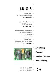
Bestückungsplan - PCB layout<br />
<strong>PZS</strong>-1<br />
Plan d´implantation - Printplan � � � Fig. 1<br />
Seite - Page - Page - Pagina I.2
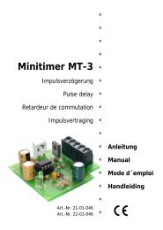
<strong>PZS</strong>-1 <strong>PZS</strong>-1<br />
Schaltplan<br />
Circuit diagram<br />
Schéma de principe<br />
Schakelschema<br />
� � � Fig. 2<br />
R10 Bremsdauer 2<br />
R11 Langsamfahrzeit<br />
R12 Aufenthaltsdauer<br />
R13 Bremsdauer 1<br />
R10 Length of braking phase 2<br />
R11 Length of reduce speed<br />
R12 Duration of stop<br />
R13 Length of braking phase 1<br />
R10 Durée de freinage 2<br />
R11 Durée de vitesse réduite<br />
R12 Durée d´arrêt<br />
R13 Durée de freinage 1<br />
R10 Remtijd 2<br />
R11 Langzaamrijden<br />
R12 Oponthoudtijd<br />
R13 Remtijd 1<br />
Seite - Page - Page - Pagina II Seite - Page - Page - Pagina II
<strong>PZS</strong>-1 <strong>PZS</strong>-1<br />
� � � Fig. 3:<br />
Anschlußplan<br />
Connections<br />
Plan de<br />
Raccordement<br />
Aansluit plan<br />
Seite - Page - Page - Pagina III Seite - Page - Page - Pagina III
Aktuelle Informationen und Tipps:<br />
Information and tips:<br />
Informations et conseils:<br />
Actuele informatie en tips:<br />
http://www.tams-online.de �<br />
Garantie und Service:<br />
Warranty and service:<br />
Garantie et service:<br />
Garantie en service:<br />
<strong>Tams</strong> Elektronik GmbH �<br />
Rupsteinstraße 10<br />
D-30625 Hannover<br />
fon: 0049 (0)511 / 55 60 60<br />
fax: 0049 (0)511 / 55 61 61<br />
e-mail: modellbahn@tams-online.de<br />
�<br />
�<br />
�<br />
�<br />
�<br />
�<br />
�<br />
�<br />
�<br />
�<br />
�<br />
�<br />
�<br />
�