Optical Fiber Sensors for Biomedical Applications
Optical Fiber Sensors for Biomedical Applications
Optical Fiber Sensors for Biomedical Applications
You also want an ePaper? Increase the reach of your titles
YUMPU automatically turns print PDFs into web optimized ePapers that Google loves.
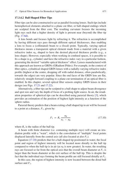
17 <strong>Optical</strong> <strong>Fiber</strong> <strong>Sensors</strong> <strong>for</strong> <strong>Biomedical</strong> <strong>Applications</strong> 67317.3.4.2 Ball Shaped <strong>Fiber</strong> Tips<strong>Fiber</strong> tips can be also constructed to act as parallel focusing lenses. Such tips includehemispherical elements attached to a plane cut fiber, or ball-shaped endings whichare sculpted from the fiber core. The resulting curvature focuses the incominglight rays such that a higher density of light is present near (beyond) the fiber tip(Fig. 17.6d).A lens bends and focuses light by refracting it. The refraction is accomplishedby having different rays pass through different optical thicknesses, thus enablinga lens to focus a (collimated) beam to a (focal) point. Typically, varying opticalthickness means a transparent optical element made from a material with a givenrefractive index n 0 , shaped to have the desired physical thickness profile (e.g., alens-shape). However, especially when working in confined spaces, it is possible tofix a shape (e.g., cylinder) and have the refractive index vary in a particular fashion,generating the desired “variable optical thickness” effect. Lenses manufactured withthis approach are known as GRINs (GRadient INdex). For example, in the context offiber optics, cylindrical shaped GRIN lenses with a radially-varying refractive indexprofile (highest at the centre, dropping off with radial distance, often parabolically,towards the edges) are very popular. Since the end faces of the GRIN lens are flat,relatively straight-<strong>for</strong>ward coupling to a plane-cut termination of an optical fiber isenabled. In this chapter, several optical fiber sensors employ GRIN lenses in theirdesign (see Figs. 17.21 and 17.22).Alternatively, a fiber tip can be sculpted to a ball shape to adjust beam divergenceand spot size and vary the depth of focus of a probing light source. In air, the irradiationproperties of spherical tips can be described using paraxial theory [3], whichprovides an estimation of the position of highest light intensity as a function of thesphere radius.Paraxial theory predicts that a beam exiting a ball shaped tip in air will be focusedto a point at a distance, F 1 , given by:F 1 = R sn 0n 1 − n 0(17.10)where R s is the radius of the ball tip.A beam with finite diameter (i.e. containing multiple rays) will create an irradiationprofile with a “waist”, which is the convolution of “multiple” focal pointsdisplaced laterally from the central axis (all also located at also F 1 ).Equation (17.10) predicts that <strong>for</strong> a ball-shaped tip positioned in water, the focalpoint and region of highest intensity will be located more distally to the ball tipcompared to when the ball tip is in air (as n 0 is now greater). In water, the resultingrays are focused so far from the optical axis that the overall beam diameter at F 1 islarger than the beam diameter at the exit surface of the ball tip. This is despite thefact that the individual rays <strong>for</strong>ming the beam profile are still focused distally at F 1 .In this case, the region of highest intensity is now located between the distal ballsurface and F 1 .


