Optical Fiber Sensors for Biomedical Applications
Optical Fiber Sensors for Biomedical Applications
Optical Fiber Sensors for Biomedical Applications

You also want an ePaper? Increase the reach of your titles
YUMPU automatically turns print PDFs into web optimized ePapers that Google loves.
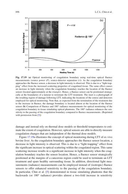
696 L.C.L. Chin et al.Fig. 17.19 (a) <strong>Optical</strong> monitoring of coagulation boundary using real-time optical fluencemeasurements (source power (P), source-detector separation (r)). As the coagulation boundaryapproaches the fluence sensor, a decrease in light intensity is observed. This is due to a “light trapping”effect from the increased scattering properties of coagulated tissue. The same effect causesan increase in light intensity when the coagulation boundary reaches the location of the fluencesensor (located approximately at the triangle). Hence, a fluence sensor can be positioned strategicallyat the boundaries of a tumour to terminate the LTT treatment. The inset is a photograph ofthe resulting region of damage following LTT, indicating the locations of the source and detectorsemployed <strong>for</strong> optical monitoring. Note that, as expected from the termination of the treatment dueto the increase in fluence, the damage boundary is located almost at the location of the fluencesensor (b) Comparison of fluence and 180 ◦ radiance measurements <strong>for</strong> optical monitoring of thecoagulation boundary in tissue simulating optical phantoms. The 180 ◦ radiance enhances the sensitivityto the passing of the coagulation boundary compared to fluence measurements. (Reprintedwith permission from [5])damage and instead rely on thermal dose models or threshold temperatures to estimatethe extent of coagulation. However, optical sensors are able to directly measurecoagulation changes that are independent of the thermal dose models.Figure 17.19a illustrates the concept of optical monitoring during LTT of ex vivobovine liver. As the coagulation boundary approaches the fluence sensor location, adecrease in light intensity is observed. This is due to a “light trapping” effect fromthe significant increase in optical scattering within the coagulated region. This samescattering increase results in a significant increase in light intensity when the coagulationboundary reaches the sensor location. Hence, a fluence sensor strategicallypositioned at the margins of a cancerous region could be used to terminate an LTTtreatment and spare healthy surrounding tissue. In addition, directional light measurements(radiance) measurements can be employed instead of (isotropic) fluencesensors to offer enhanced sensitivity to the passing of the coagulation boundary.In particular, Chin et al. [5] demonstrated in tissue simulating phantoms that thebackwards (or 180 ◦ radiance) provides almost a two-fold increase in sensitivity