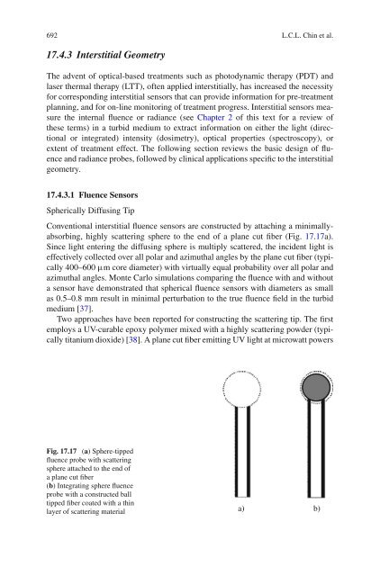
692 L.C.L. Chin et al.17.4.3 Interstitial GeometryThe advent of optical-based treatments such as photodynamic therapy (PDT) andlaser thermal therapy (LTT), often applied interstitially, has increased the necessity<strong>for</strong> corresponding interstitial sensors that can provide in<strong>for</strong>mation <strong>for</strong> pre-treatmentplanning, and <strong>for</strong> on-line monitoring of treatment progress. Interstitial sensors measurethe internal fluence or radiance (see Chapter 2 of this text <strong>for</strong> a review ofthese terms) in a turbid medium to extract in<strong>for</strong>mation on either the light (directionalor integrated) intensity (dosimetry), optical properties (spectroscopy), orextent of treatment effect. The following section reviews the basic design of fluenceand radiance probes, followed by clinical applications specific to the interstitialgeometry.17.4.3.1 Fluence <strong>Sensors</strong>Spherically Diffusing TipConventional interstitial fluence sensors are constructed by attaching a minimallyabsorbing,highly scattering sphere to the end of a plane cut fiber (Fig. 17.17a).Since light entering the diffusing sphere is multiply scattered, the incident light iseffectively collected over all polar and azimuthal angles by the plane cut fiber (typically400–600 μm core diameter) with virtually equal probability over all polar andazimuthal angles. Monte Carlo simulations comparing the fluence with and withouta sensor have demonstrated that spherical fluence sensors with diameters as smallas 0.5–0.8 mm result in minimal perturbation to the true fluence field in the turbidmedium [37].Two approaches have been reported <strong>for</strong> constructing the scattering tip. The firstemploys a UV-curable epoxy polymer mixed with a highly scattering powder (typicallytitanium dioxide) [38]. A plane cut fiber emitting UV light at microwatt powersFig. 17.17 (a) Sphere-tippedfluence probe with scatteringsphere attached to the end ofa plane cut fiber(b) Integrating sphere fluenceprobe with a constructed balltipped fiber coated with a thinlayer of scattering materiala) b)
17 <strong>Optical</strong> <strong>Fiber</strong> <strong>Sensors</strong> <strong>for</strong> <strong>Biomedical</strong> <strong>Applications</strong> 693is shone into the epoxy mixture. The resulting fluence pattern is then an isotropicspherical distribution that <strong>for</strong>ms symmetrically around the fiber tip. Following the<strong>for</strong>mation of the scattering tip, the epoxy is irradiated at higher powers to fullysolidify.A variation of this geometry is to employ a fiber with a ball-shaped tip insteadof a plane cut fiber and grow a thin layer of scattering material around the tip(Fig. 17.17b). The spherically tipped fiber can be purchased through commercialvendors, or constructed in-house by employing a small torch to melt the fiber tip attemperature >2500 ◦ C to the desired ball shape. Here the optical fiber tip acts as anintegrating sphere and requires less scattering epoxy compared to a bare-tipped fiberto fully randomize the direction of the incoming light. An additional advantage ofthis configuration is that if the fluence sensor is employed as an isotropic sphericalsource, higher input powers can be utilized, since the absorbed heat is dissipatedover the entire spherical surface instead of being concentrated in the vicinity of thesmaller bare-tip area.A second method is to attach a pre-fabricated sphere, typically made of Arnite,ceramic, or Teflon, to the end of a bare tip, plane cut fiber [39, 40]. A small hole isbored to the center midway point of the sphere, the sphere is then “skewered” by thefiber and fixed using glue to the end of the fiber tip.The primary weakness of scattering sphere probes is that sizeable diameters(∼1–2 mm) are required to achieve a desired level of collection isotropy and that aninherent “blind-spot” is present at the stem region of the probe. Typically, a 3 mmdiameterprobe can achieve an isotropy to within ± 15%, while a ∼1 mm-diameterprobe is isotropic to within ∼± 20% over a 320 angular range [39, 40]. Finally,during clinical application, the spherical tip can become unattached from the fibercore if the sensor is pulled back too quickly or awkwardly during its positioning,manipulation, or removal.Fluorescent Dye-Loaded TipTo overcome the size limitations of scattering-sphere probes, Lilge et al. [41]developedfluorescent dye-loaded fluence sensors. The use of fluorescent dyes overcomesthe limitations of larger scattering-based spherical sensors, because fluorescenceemission is naturally isotropic. As such, the isotropy of the sensor is dependent onlyon the tip shape and not its size [41].The sensor designs are illustrated in Fig. 17.18. First, a polymethlyl methacrylate(PMMA) dye-free offset is attached to the end of a plane cut fiber (Fig. 17.18a). Theoffset effectively serves as a spacer between the dye-sensitive region and the fiber.Next, a dye-loaded PMMA tip is added to the offset. The dye-free and dye-loadedPMMA are constructed using methyl-methacrylate (MMA), which is polymerizedin an oven at 60 C <strong>for</strong> ∼48 h and initiated using a primer (Azobis, Polyscience,Milwaukee, Wi, USA). The addition of dimethyl chloride (DMC) changes the solidpolymerized PMMA to a viscous <strong>for</strong>m. As such, fluorescent dyes dissolved in DMCcan be added to the solid PMMA. Following evaporation of DMC, the dye remainsabsorbed in the PMMA.