Optical Fiber Sensors for Biomedical Applications
Optical Fiber Sensors for Biomedical Applications
Optical Fiber Sensors for Biomedical Applications

Create successful ePaper yourself
Turn your PDF publications into a flip-book with our unique Google optimized e-Paper software.
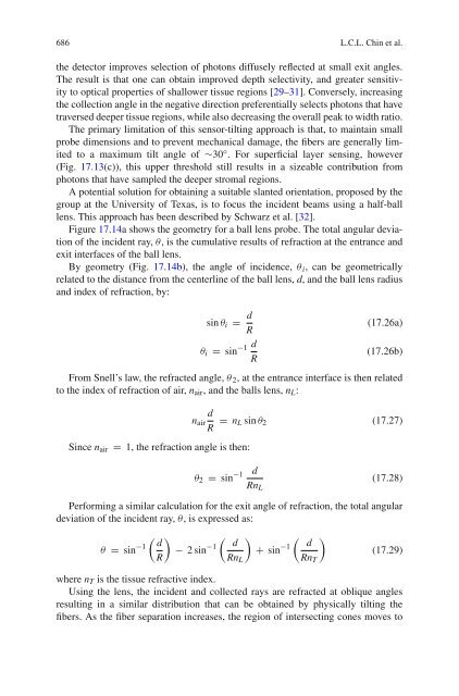
686 L.C.L. Chin et al.the detector improves selection of photons diffusely reflected at small exit angles.The result is that one can obtain improved depth selectivity, and greater sensitivityto optical properties of shallower tissue regions [29–31]. Conversely, increasingthe collection angle in the negative direction preferentially selects photons that havetraversed deeper tissue regions, while also decreasing the overall peak to width ratio.The primary limitation of this sensor-tilting approach is that, to maintain smallprobe dimensions and to prevent mechanical damage, the fibers are generally limitedto a maximum tilt angle of ∼30 ◦ . For superficial layer sensing, however(Fig. 17.13(c)), this upper threshold still results in a sizeable contribution fromphotons that have sampled the deeper stromal regions.A potential solution <strong>for</strong> obtaining a suitable slanted orientation, proposed by thegroup at the University of Texas, is to focus the incident beams using a half-balllens. This approach has been described by Schwarz et al. [32].Figure 17.14a shows the geometry <strong>for</strong> a ball lens probe. The total angular deviationof the incident ray, θ, is the cumulative results of refraction at the entrance andexit interfaces of the ball lens.By geometry (Fig. 17.14b), the angle of incidence, θ i , can be geometricallyrelated to the distance from the centerline of the ball lens, d, and the ball lens radiusand index of refraction, by:sin θ i = d Rθ i = sin −1 d R(17.26a)(17.26b)From Snell’s law, the refracted angle, θ 2 , at the entrance interface is then relatedto the index of refraction of air, n air , and the balls lens, n L :dn airR = n L sin θ 2 (17.27)Since n air = 1, the refraction angle is then:θ 2 = sin −1dRn L(17.28)Per<strong>for</strong>ming a similar calculation <strong>for</strong> the exit angle of refraction, the total angulardeviation of the incident ray, θ, is expressed as:( ) ( ) ( )d ddθ = sin −1 − 2sin −1 + sin −1 (17.29)RRn L Rn Twhere n T is the tissue refractive index.Using the lens, the incident and collected rays are refracted at oblique anglesresulting in a similar distribution that can be obtained by physically tilting thefibers. As the fiber separation increases, the region of intersecting cones moves to