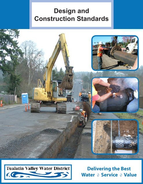
Design and Construction Standards - Tualatin Valley Water District
Design and Construction Standards - Tualatin Valley Water District
Design and Construction Standards - Tualatin Valley Water District

You also want an ePaper? Increase the reach of your titles
YUMPU automatically turns print PDFs into web optimized ePapers that Google loves.
<strong>Design</strong> <strong>and</strong><strong>Construction</strong> St<strong>and</strong>ardsDelivering the Best<strong>Water</strong> Service Value
TUALATIN VALLEY WATER DISTRICTWATER SYSTEM DESIGN AND CONSTRUCTION STANDARDS1850 SW 170th AvenueBeaverton, Oregon 97006Phone: 503-642-1511Effective Revision Date:June 20, 2012
Table of ContentsList of TablesList of St<strong>and</strong>ard DetailsDefinitions, Acronyms, <strong>and</strong> Abbreviationsivvvii1. General Requirements1.1 Scope <strong>and</strong> Definitions ................................................................................................................... 1-11.2 General Process for <strong>Water</strong> System Improvements ..................................................................... 1-11.3 Preparation <strong>and</strong> Submittal of Engineering Plans ........................................................................ 1-21.4 Approval of Engineering Plans...................................................................................................... 1-31.5 <strong>Construction</strong> Inspection ................................................................................................................ 1-31.6 Electronic ....................................................................................................................................... 1-41.7 Requirements for Acceptance of <strong>Water</strong> System Improvements ................................................ 1-41.8 Warranty ........................................................................................................................................ 1-41.9 Easements ..................................................................................................................................... 1-51.10 General <strong>Design</strong> Requirements ..................................................................................................... 1-51.11 General Materials Requirements ................................................................................................. 1-51.12 General <strong>Construction</strong> Requirements ........................................................................................... 1-6b. Safety <strong>and</strong> Worksite Conditions ................................................................................................. 1-6a. Permits <strong>and</strong> Road Closures ........................................................................................................ 1-6c. Valve Operations Prohibited ....................................................................................................... 1-6d. Interruption of Utility Service ...................................................................................................... 1-6e. Damage to <strong>Water</strong> System during <strong>Construction</strong> ......................................................................... 1-6f. Relocation of Existing Mains ....................................................................................................... 1-7g. <strong>Water</strong> Service Installation ........................................................................................................... 1-7h. Connections to the <strong>Water</strong> System .............................................................................................. 1-7i. Preservation of L<strong>and</strong> Survey Monuments .................................................................................. 1-7j. Permits <strong>and</strong> Road Closures ........................................................................................................ 1-7k. Substitution of Materials ............................................................................................................. 1-72. Trench Excavation <strong>and</strong> Backfill2.1 Types of Allowed Backfill .............................................................................................................. 2-12.2 Materials ........................................................................................................................................ 2-1a. Class A Backfill – compacted native material ........................................................................... 2-1b. Class B Backfill – compacted crushed rock granular material ................................................ 2-1c. Bedding <strong>and</strong> Pipe Zone Material ................................................................................................ 2-1d. Foundation Stabilization Material .............................................................................................. 2-12.3 Pavement, Curb, <strong>and</strong> Sidewalk Removal ..................................................................................... 2-22.4 Trench Width, Base, <strong>and</strong> Grade ................................................................................................... 2-2TVWD <strong>Water</strong> System St<strong>and</strong>ards June 2012 Page i
<strong>Water</strong> System <strong>Design</strong> <strong>and</strong> <strong>Construction</strong> St<strong>and</strong>ardsTable of Contents2.5 Shoring, Sheeting, <strong>and</strong> Bracing of Trenches ............................................................................... 2-22.6 Location of Excavated Materials .................................................................................................. 2-22.7 Removal of <strong>Water</strong> .......................................................................................................................... 2-32.8 Addition <strong>and</strong> Compaction of Backfill ............................................................................................ 2-3a. Bedding <strong>and</strong> Pipe Zone ............................................................................................................... 2-3b. Class A Backfill ............................................................................................................................ 2-3c. Class B Backfill ............................................................................................................................ 2-3g. Settlement ................................................................................................................................... 2-42.9 Compaction Testing ...................................................................................................................... 2-42.10 General Surface Restoration Specifications ............................................................................... 2-4a. Asphalt Concrete <strong>and</strong> Portl<strong>and</strong> Cement Concrete Paving ........................................................ 2-4b. Protection of Structures .............................................................................................................. 2-5c. Warranty Period ........................................................................................................................... 2-53. <strong>Water</strong> Mains3.1 <strong>Design</strong> ............................................................................................................................................ 3-1b. Pipe Sizes ..................................................................................................................................... 3-1c. Location of Mains ........................................................................................................................ 3-1d. Dead End Mains .......................................................................................................................... 3-1f. Pipe Alignment ............................................................................................................................. 3-2g. Restrained Joints ......................................................................................................................... 3-2h. Casing Pipe, Spacers, <strong>and</strong> Seals ................................................................................................ 3-3i. Cathodic Protection ..................................................................................................................... 3-33.2 Materials ........................................................................................................................................ 3-3c. Restrained Joint Ductile Iron Pipe .............................................................................................. 3-3d. Ductile Iron Fittings ..................................................................................................................... 3-4e. Mechanical Joint Fittings <strong>and</strong> Restraints ................................................................................... 3-4f. Flanged Fittings ........................................................................................................................... 3-5g. Gaskets ........................................................................................................................................ 3-5h. Restrained Joints ......................................................................................................................... 3-5i. Sleeves <strong>and</strong> Mechanical Couplings ............................................................................................ 3-5j. Tapping Sleeves .......................................................................................................................... 3-6k. Casing Pipe, Spacers, <strong>and</strong> Seals ................................................................................................ 3-63.3 <strong>Construction</strong> .................................................................................................................................. 3-7a. Cutting the Pipe ........................................................................................................................... 3-7b. Laying the Pipe………………………………………………………………………………………………………………3-7c. Tapping Sleeves .......................................................................................................................... 3-9d. Thrust Blocks…………………………………………………………………………………………………………………3-9e. Straddle Blocks……………………………………………………………………………………………………………..3-93.4 Hydrostatic Testing, Flushing, <strong>and</strong> Disinfection ........................................................................ 3-10a. Hydrostatic Test .........................................................................................................................3-10TVWD <strong>Water</strong> System St<strong>and</strong>ards June 2012 Page ii
<strong>Water</strong> System <strong>Design</strong> <strong>and</strong> <strong>Construction</strong> St<strong>and</strong>ardsTable of Contentsb. Flushing ......................................................................................................................................3-11c. Disinfection of Pipelines ...........................................................................................................3-114. Valves <strong>and</strong> Valve Boxes4.1 General Requirements .................................................................................................................. 4-1a. Isolation Valve Size, Spacing, <strong>and</strong> Location .............................................................................. 4-1b. Pressure Reducing Valves .......................................................................................................... 4-1c. Strainers ....................................................................................................................................... 4-1d. Air <strong>and</strong> Vacuum Release Valves ................................................................................................. 4-14.2 Materials ........................................................................................................................................ 4-2a. Gate Valves .................................................................................................................................. 4-2b. Butterfly Valves ............................................................................................................................ 4-2c. Acceptable Manufacturers .......................................................................................................... 4-2d. Valve Operators ........................................................................................................................... 4-3e. Valve Boxes for Buried Gate <strong>and</strong> Butterfly Valves ..................................................................... 4-3f. Pressure Reducing Valves .......................................................................................................... 4-3g. Pressure Relief Valves................................................................................................................. 4-4h. ‘H’ Strainers ................................................................................................................................. 4-4i. Air <strong>and</strong> Vacuum Release Valves ................................................................................................. 4-44.3 <strong>Construction</strong> .................................................................................................................................. 4-4a. Gate <strong>and</strong> Butterfly Valve Installation .......................................................................................... 4-4b. Gate <strong>and</strong> Butterfly Valve Boxes .................................................................................................. 4-5c. Air <strong>and</strong> Vacuum Release Valve Boxes ........................................................................................ 4-55. Fire Hydrants5.1 Fire Hydrant Locations .................................................................................................................. 5-15.2 Materials ........................................................................................................................................ 5-15.3 <strong>Construction</strong> .................................................................................................................................. 5-2a. Hydrant Installation ..................................................................................................................... 5-26. <strong>Water</strong> Service Connections6.1 General Requirements ................................................................................................................. 6-1d. Curbs ............................................................................................................................................ 6-1e. Service Installation ...................................................................................................................... 6-1f. <strong>Water</strong> Services <strong>and</strong> Meters ......................................................................................................... 6-16.2 Materials ........................................................................................................................................ 6-3b. Corporation Stops ........................................................................................................................ 6-3c. Tapping Saddles .......................................................................................................................... 6-3e. Meter Boxes <strong>and</strong> Covers ............................................................................................................. 6-36.3 <strong>Construction</strong> .................................................................................................................................. 6-4a. Installation of Service Connections ............................................................................................ 6-47. Precast Concrete Vaults7.1 Vault <strong>Design</strong> .................................................................................................................................. 7-1TVWD <strong>Water</strong> System St<strong>and</strong>ards June 2012 Page iii
<strong>Water</strong> System <strong>Design</strong> <strong>and</strong> <strong>Construction</strong> St<strong>and</strong>ardsTable of Contents7.2 Vault Materials .............................................................................................................................. 7-1b. Precast Concrete Vaults .............................................................................................................. 7-1c. Ladders ........................................................................................................................................ 7-1d. Drainage ....................................................................................................................................... 7-2e. Sumps .......................................................................................................................................... 7-2f. Sidewalk Door .............................................................................................................................. 7-2g. Vault Joints ................................................................................................................................... 7-3h. Grout <strong>and</strong> Dampproof Coatings .................................................................................................. 7-37.3 Vault Installation ........................................................................................................................... 7-3d. Pipe Penetrations ........................................................................................................................ 7-38. Backflow Prevention General Requirements8.1 Purpose <strong>and</strong> General Requirements ........................................................................................... 8-18.2 Cases Where Backflow Prevention Assemblies are Required ................................................... 8-18.3 Types of Backflow Preventers ...................................................................................................... 8-28.4 Installation of Double Check Valve Assemblies <strong>and</strong> Reduced Pressure Backflow Assemblies8-4a. Installation Locations .................................................................................................................. 8-4b. Meter Boxes for Assemblies ....................................................................................................... 8-4c. Below Grade Vault Installation ................................................................................................... 8-5d. Above Ground Installation ........................................................................................................... 8-58.5 Installation of Double Check Detector Assemblies <strong>and</strong> Reduced Pressure Detector Assemblies8-6a. General Requirements ................................................................................................................ 8-6b. Detector Meters ........................................................................................................................... 8-6c. Below Grade Vault Installation ................................................................................................... 8-7d. Above Ground Installation ........................................................................................................... 8-78.6 Installation of Pressure Vacuum Breaker, Spill-Resistant Vacuum Breaker, <strong>and</strong> AtmosphereVacuum Breaker Assemblies ....................................................................................................... 8-7a. Grade Requirements ................................................................................................................... 8-78.7 Installation of Air Gaps .................................................................................................................. 8-7a. General Requirements ................................................................................................................ 8-7List of TablesTable 1. Maximum Allowable Deflection of DI PIPE Joints (18-foot pipe length) 1, 2 ............... 3-2Table 2. Acceptable Tapping Sleeves ........................................................................................ 3-6Table 3. Hypochlorite Solution ................................................................................................ 3-12Table 4. Required Meter Boxes .................................................................................................. 6-3Table 5. Required Angle Valves ................................................................................................. 6-3Table 6. Suggested Meter Boxes ............................................................................................... 8-4TVWD <strong>Water</strong> System St<strong>and</strong>ards June 2012 Page iv
<strong>Water</strong> System <strong>Design</strong> <strong>and</strong> <strong>Construction</strong> St<strong>and</strong>ardsTable of ContentsList of St<strong>and</strong>ard DetailsSt<strong>and</strong>ard Detail Title1 Typical <strong>Water</strong> Valve Location3 Typical Valve Setting5 Valve Operator Extension7 Single <strong>Water</strong> Service Typical Installation with Curbtight Sidewalk7DDual <strong>Water</strong> Service Typical Installation with Curbtight Sidewalk7PSingle <strong>Water</strong> Service Typical Installation with Planter Strip7PDDual <strong>Water</strong> Service Typical Installation with Planter Strip8 Tapping Saddle9 Typical Commercial/Industrial Service Layout10 Typical Trench Backfill21 Restrained Length (Feet) Required from Common Fittings50 Sample Station Installation100 Typical <strong>Water</strong> Main <strong>and</strong> Fire Hydrant Location101 Fire Hydrant St<strong>and</strong>ard Installation102 Fire Hydrant Clear Zone200 Straddle Block202 Phase Break End for Future Extension (4” – 10” Mainline)203 2" St<strong>and</strong>ard Blowoff (4” – 10” Mainline)205 6” St<strong>and</strong>ard Blowoff in Manhole300 Vault Ladder Installation310 Sump Pump Installation601 1” Combination Air <strong>and</strong> Vacuum Valve602 2" Combination Air <strong>and</strong> Vacuum Valve702 1 ½" & Larger Meter Installation w/ Backflow Device703C3" - 6” Meter Installation by Contractor763C6" x 3" Meter Installation by Contractor784C8" x 4" Meter Installation by Contractor811 4” Pressure Relief Vault, Contractor InstalledSt<strong>and</strong>ard DetailBF10BF100BF101BF102BF103BF200TitleTypical Backflow Preventers for Lawn Sprinkler SystemsDouble Check Valve Assembly1” Double Check Assembly1-1/2", 2" & 2-1/2" Double Check InstallationDouble Check Valve Assembly Customer Owned (Above Ground)Double Check Detector AssemblyTVWD <strong>Water</strong> System St<strong>and</strong>ards June 2012 Page v
<strong>Water</strong> System <strong>Design</strong> <strong>and</strong> <strong>Construction</strong> St<strong>and</strong>ardsTable of ContentsBF201 Double Check Detector Assembly - Customer Owned (Above Ground) 3" - 10"BF202Reduced Pressure Detector Backflow Assembly 2-1/2” – 10” Customer Owned(Above Ground)BF203Reduced Pressure Detector Backflow Assembly 2-1/2” – 10” Customer Owned(Above Ground) In VaultBF300Reduced Pressure Backflow Assembly 2-1/2” – 10” Customer Owned (AboveGround)BF3011" Reduced Pressure Backflow PreventerBF3021-1/2" & 2" Reduced Pressure Backflow DeviceBF303Reduced Pressure Backflow Assembly Customer Owned (Above Ground) In VaultBF304Reduced Pressure Backflow Assembly Discharge RatesBF500Minimum Protection for Filling Tanker TrucksBF501Air GapTVWD <strong>Water</strong> System St<strong>and</strong>ards June 2012 Page vi
<strong>Water</strong> System <strong>Design</strong> <strong>and</strong> <strong>Construction</strong> St<strong>and</strong>ardsTable of ContentsDefinitions, Acronyms, <strong>and</strong> AbbreviationsDefinitionsContractorDeveloper<strong>District</strong><strong>District</strong> EngineerInspectorOwnerProject EngineerSt<strong>and</strong>ard DetailsSt<strong>and</strong>ardsAcronymsNote:ANSIASTMAWWANSFODOTULAbbreviationsThe person or entity employed by the Developer, Owner, or <strong>District</strong> in order toimplement water system improvements.The person or entity legally responsible for the development of l<strong>and</strong>.The <strong>Tualatin</strong> <strong>Valley</strong> <strong>Water</strong> <strong>District</strong>.The <strong>District</strong>’s Chief Engineer, or his/her authorized representative.The person employed by the <strong>District</strong> to observe construction <strong>and</strong> enforce the<strong>District</strong>’s <strong>Water</strong> System St<strong>and</strong>ards <strong>and</strong> proper construction of water systemimprovements.The person or entity who possesses legal ownership of the l<strong>and</strong> affected by theimprovements.The engineer in responsible charge of designing the water system improvements,who must be registered in the State of Oregon.Detail drawings showing specific installation details for water systemcomponents.The <strong>Tualatin</strong> <strong>Valley</strong> <strong>Water</strong> <strong>District</strong> <strong>Water</strong> System <strong>Design</strong> <strong>and</strong> <strong>Construction</strong>St<strong>and</strong>ards.When references to the following capitalized abbreviations are made, they refer toSpecifications, St<strong>and</strong>ards or Methods of the respective association or agency.American National St<strong>and</strong>ards InstituteAmerican Society for Testing <strong>and</strong> MaterialsAmerican <strong>Water</strong> Works AssociationNSF International (formerly National Sanitation Foundation)Oregon Department of TransportationUnderwriter's Laboratories, Inc.BCR Beginning of Curb Return G.I. Galvanized IronB.F.V. Butterfly Valve G.V. Gate ValveB.O. Blowoff M.J. Mechanical Joint (fitting)CARV Combination Air/Vacuum Release Valve P.E. Plain End (pipe)D.I. Ductile Iron (pipe) ppm Parts Per MillionECR End of Curb Return PSI Pounds Per Square Inch (pressure)Flg. Flange (fitting) PRV Pressure Reducing Valvefps Feet Per Second PUE Public Utility EasementTVWD <strong>Water</strong> System St<strong>and</strong>ards June 2012 Page vii
Section 1General Requirements1.1 Scope <strong>and</strong> Definitionsa. The <strong>Tualatin</strong> <strong>Valley</strong> <strong>Water</strong> <strong>District</strong> <strong>Water</strong> System St<strong>and</strong>ards includes provisions,technical specifications, <strong>and</strong> requirements for construction within the <strong>Tualatin</strong><strong>Valley</strong> <strong>Water</strong> <strong>District</strong>, <strong>and</strong> other entities managed by the <strong>District</strong>.b. In addition to following these St<strong>and</strong>ards, water system design <strong>and</strong> constructionshall abide by all relevant codes, ordinances, <strong>and</strong> regulations. In cases ofconflicting requirements, the more stringent st<strong>and</strong>ard shall apply.c. St<strong>and</strong>ard Details are included in these St<strong>and</strong>ards to supplement the writtenspecifications, but the written specifications shall have precedence over thest<strong>and</strong>ard details in the event of conflicts.d. The <strong>District</strong> Engineer has the authority to recommend or allow deviations fromthese St<strong>and</strong>ards in necessary circumstances, according to his or her bestjudgment.e. Public health <strong>and</strong> safety shall be adequately protected in the Project Engineer’sdesigns <strong>and</strong> at all times during construction of water system improvements.f. All construction <strong>and</strong> other water system-related work shall be performed byexperienced workers using tools in good repair to a high quality of workmanship.The <strong>Tualatin</strong> <strong>Valley</strong> <strong>Water</strong> <strong>District</strong> may revise the St<strong>and</strong>ards at any time without prior notification.Any amendment shall take effect upon the date indicated in the amendment upon posting to the<strong>District</strong>’s website.1.2 General Process for <strong>Water</strong> System Improvementsa. In general, the process for designing <strong>and</strong> installing water system improvementsshall be as follows:1. The Developer shall submit engineering plans prepared by the Project Engineer <strong>and</strong>sealed with professional engineers stamp in accordance with ORS 672, along withthe plan review fee.2. The <strong>District</strong> shall review the engineering plans. If changes <strong>and</strong> revisions arerequired, the Project Engineer shall revise <strong>and</strong> resubmit the plans.3. Following approval of plans by the <strong>District</strong>, the Developer’s Contractor shall installthe improvements in accordance with the approved plans.4. The <strong>District</strong>’s Inspector’s shall monitor <strong>and</strong> inspect the work throughoutconstruction to ensure compliance with the approved plans <strong>and</strong> <strong>District</strong> St<strong>and</strong>ards.5. Upon completion of the work, the Developer shall submit As-Built Drawingsprepared by the Project Engineer.TVWD <strong>Water</strong> System St<strong>and</strong>ards June 2012 Page 1-1
<strong>Water</strong> System <strong>Design</strong> <strong>and</strong> <strong>Construction</strong> St<strong>and</strong>ards Section 16. After final acceptance by the <strong>District</strong>, the Developer shall provide a one yearwarranty on the improvements.b. Prior to initiating the project design, the Project Engineer shall contact the <strong>District</strong>Engineer, who may suggest or require a pre-design meeting to discuss thespecific requirements for the project.1.3 Preparation <strong>and</strong> Submittal of Engineering Plansa. All plans for water system improvements must be prepared <strong>and</strong> sealed by aProject Engineer who is licensed by the state of Oregon.b. Generally, engineering plans shall include the following information:1. Existing <strong>and</strong> proposed utilities (sewer, storm, power, gas, telecom, cable, poles,etc.)2. Existing <strong>and</strong> proposed curbs, sidewalks, driveways, mailboxes, <strong>and</strong> other streetfeatures.3. Existing <strong>and</strong> proposed rights-of-way <strong>and</strong> easements.4. Horizontal <strong>and</strong> vertical alignments of new public mains.5. Size, material, <strong>and</strong> location of new <strong>and</strong> existing water mains <strong>and</strong> services.6. Size, type, <strong>and</strong> location of new <strong>and</strong> existing water appurtenances, including:i. Valvesii. Hydrantsiii. Fittings (Bends, Tees, Crosses, Reducers)iv. Pressure Regulatorsv. Vaultsvi. Meters7. Joint restraint requirements.8. Cathodic protection requirements.9. <strong>District</strong> St<strong>and</strong>ard Details that are applicable to the project.10. Existing <strong>and</strong> required easements for water improvements.11. Proper call-outs <strong>and</strong> notation.c. If applicable, include drawings showing:1. L<strong>and</strong>scaping plans showing the layout of irrigation systems, backflow device(s), <strong>and</strong>any decorative water features.2. Mechanical plans of boilers, chillers, <strong>and</strong> other water-consuming mechanicaldevices.3. Plumbing plans with location of on-site backflow devices; fire line drawings showingplans of antifreeze (either potable or non-potable) loops, etc.TVWD <strong>Water</strong> System St<strong>and</strong>ards June 2012 Page 1-2
<strong>Water</strong> System <strong>Design</strong> <strong>and</strong> <strong>Construction</strong> St<strong>and</strong>ards Section 1d. All drawings submitted for review <strong>and</strong> approval shall be on sheets with a size ofeither 22 inches by 34 inches or 24 inches by 36 inches.e. Minimum text height shall be 0.10 inch.f. Plans shall include a cover sheet with the following information:1. Project name.2. Owner’s name, address, phone number, fax number, <strong>and</strong> email address.3. Project Engineer’s name, address, phone number, fax number, <strong>and</strong> email address.4. Contractor’s name, address, phone number, fax number, <strong>and</strong> email address.5. Project location (Vicinity Map)g. Submit plan review fee <strong>and</strong> three sets of subdivision drawings to the <strong>District</strong>Engineer for review <strong>and</strong> approval: one full set <strong>and</strong> two partial sets of drawingsheets showing only the water system improvements.1.4 Approval of Engineering Plansa. The <strong>District</strong> Engineer’s approval of the sealed plans is required prior to the startof any construction. Plan approvals are only valid for six months from the date ofapproval.b. Any changes to approved plans initiated by the Project Engineer or as a result offield conditions must be resubmitted <strong>and</strong> approved by the <strong>District</strong> Engineer.c. The Developer or their agent shall obtain all required permits.d. Any property to be developed that is not currently within the <strong>District</strong> boundaryshall be annexed into the <strong>District</strong> prior to extending water service to the site,unless an extra-territorial water line extension has been approved.1.5 <strong>Construction</strong> Inspectiona. The Developer’s Contractor shall contact the Inspector at least 48 hours prior toany water system construction to request a pre-construction conference.b. The <strong>District</strong> Engineer <strong>and</strong> Inspector shall have access to the project at all times inorder to make routine visual inspections of the work.c. No work shall be buried before it is inspected <strong>and</strong> accepted by the Inspector.Potholing of buried water lines may be required at the Developer's expense toallow verification that the installation meets the requirements of the St<strong>and</strong>ards.d. Should any inspection reveal that construction is not proceeding according to theapproved plans <strong>and</strong>/or <strong>District</strong> St<strong>and</strong>ards, the <strong>District</strong> Engineer or Inspector mayorder all work stopped <strong>and</strong> all defective work removed <strong>and</strong> replaced. If a revisionis necessary, the Project Engineer shall provide the <strong>District</strong> Engineer with revisedplans for review <strong>and</strong> approval before work resumes.e. Work by Developer’s Contractor outside <strong>District</strong>’s normal business hours shallrequire a minimum of 48 hours notice to Inspector. Overtime costs for <strong>District</strong>inspection will be paid by the Contractor.TVWD <strong>Water</strong> System St<strong>and</strong>ards June 2012 Page 1-3
<strong>Water</strong> System <strong>Design</strong> <strong>and</strong> <strong>Construction</strong> St<strong>and</strong>ards Section 11.6 Electronic "As-Built" Drawingsa. Upon completion of new residential or commercial subdivisions, the ProjectEngineer shall submit an electronic file of the final plat <strong>and</strong> as-built drawings.b. Electronic files shall be submitted to the <strong>District</strong> Engineer via email as anattached file in AUTOCAD.DWG or .DXF format. Verify the appropriate formatversion with the <strong>District</strong>’s Inspector.c. Alternatively, electronic files may be submitted on CD media or other approvedmeans using the above-indicated file format.1.7 Requirements for Acceptance of <strong>Water</strong> System ImprovementsThe following items must be completed prior to final acceptance of water system improvements:1.8 Warrantya. Compliance with all relevant St<strong>and</strong>ards, including but not limited to st<strong>and</strong>ards fordesign, construction, disinfection, <strong>and</strong> pressure testing.b. Completion of second lift of paving, ensuring that all valve boxes are raised <strong>and</strong>flush with surface. The <strong>District</strong> may approve the installation of water meters priorto placement of the second paving lift if:1. It is during the winter period, approximately November 15 through March 15.2. Weather <strong>and</strong> temperature conditions are unacceptable for final paving.3. A deposit or bond in the amount of 10% of the value of the water systemimprovements, or a minimum of $5,000, is deposited with the <strong>District</strong> prior torelease of the subdivision for water meter installation.4. The Developer agrees to complete final paving within 30 days after pavingconditions return to acceptable temperatures.c. Request for final subdivision inspection <strong>and</strong> correction of any deficienciesidentified by <strong>District</strong> staff at the final inspection walk-through.d. Submission of electronic files for the project, as described in Section 1.6.e. Provide documentation that any required easements <strong>and</strong>/or right-of-waydedications have been completed <strong>and</strong> recorded.f. The <strong>District</strong> reserves the right to withhold installation of water meters until theproject has been granted final acceptance.a. A one-year warranty period shall be provided for the water system improvementsby the Developer. Any failure of materials <strong>and</strong> workmanship during the warrantyshall be repaired or replaced to the <strong>District</strong>’s satisfaction at the Developer’sexpense.b. The warranty period shall begin on the date of final written acceptance of theproject by <strong>Tualatin</strong> <strong>Valley</strong> <strong>Water</strong> <strong>District</strong>.TVWD <strong>Water</strong> System St<strong>and</strong>ards June 2012 Page 1-4
<strong>Water</strong> System <strong>Design</strong> <strong>and</strong> <strong>Construction</strong> St<strong>and</strong>ards Section 11.9 Easementsa. Where it is not practical or possible to install water system improvements within adedicated public right-of-way, the <strong>District</strong> may allow the improvements to beinstalled within a dedicated easement on private property.b. <strong>Water</strong> line easements shall be centered on the pipe. Minimum easement widthsshall be 15 feet for areas with vehicular access (roadways, parking lots, etc.) <strong>and</strong>20 feet for areas without vehicular access. Additional width may be required forspecial circumstances such as slopes or other cases as determined by the<strong>District</strong>.c. Easements for vaults or other water system appurtenances shall extend aminimum of 5 feet on all sides of the structure. Additional width may be requiredfor special circumstances such as slopes or other cases as determined by the<strong>District</strong>.d. Easements granted to the <strong>District</strong> shall allow for access, construction, operations,maintenance, replacement, reconstruction, <strong>and</strong> removal of the water systemimprovements.e. The easement shall be solely for water systems improvements <strong>and</strong> not shared byother utilities or structures without the prior written consent of the <strong>District</strong>.f. If access to the easement area <strong>and</strong> associated appurtenances is not directlyavailable from a public right-of-way, an access easement along the most directroute of access shall be granted to the <strong>District</strong>.g. Easement exhibits shall be prepared by a Professional L<strong>and</strong> Surveyor. Easementdimensions <strong>and</strong> language shall be subject to final approval by the <strong>District</strong>.Easements shall be recorded prior to final project approval.1.10 General <strong>Design</strong> Requirementsa. Any permanent appurtenance that is above sidewalk <strong>and</strong>/or finish grade shall beat least 18 inches behind the sidewalk. No permanent signs, structures, or plantmaterials are allowed within three feet of <strong>District</strong> facilities.b. In locations outside of the established right-of-way, mark water lineappurtenances, such as valves, blowoff assemblies, <strong>and</strong> cathodic protection teststations, with a Carsonite marking post. Post shall be blue in color, a minimumwidth of 3.5 inches, <strong>and</strong> be set with the top of post three feet above finishedgrade.1.11 General Materials Requirementsa. Only materials designed for potable water service <strong>and</strong> meeting NSF St<strong>and</strong>ard 61,the American <strong>Water</strong> Works Association (AWWA) st<strong>and</strong>ards, <strong>and</strong> other applicablest<strong>and</strong>ards shall be used in those elements of the water system which may comein contact with potable water. All materials must be certified “lead-free”.b. All materials used for water system construction shall be of new manufacture. Norebuilt, reconditioned, or previously used materials shall be used.TVWD <strong>Water</strong> System St<strong>and</strong>ards June 2012 Page 1-5
<strong>Water</strong> System <strong>Design</strong> <strong>and</strong> <strong>Construction</strong> St<strong>and</strong>ards Section 11.12 General <strong>Construction</strong> Requirementsa. Safety <strong>and</strong> Worksite Conditions1. Project safety shall be the responsibility of the contractor.2. Contractors shall use every reasonable precaution to safeguard the persons <strong>and</strong>property of the traveling public. It shall be the sole responsibility of the Contractorto furnish, place, <strong>and</strong> maintain the barricades, barriers, lights, signage, <strong>and</strong>flaggers necessary to protect the traveling public <strong>and</strong> their property.3. Contractors shall abide by all OSHA <strong>and</strong> other applicable safety regulations.4. All barricades <strong>and</strong> obstructions shall be protected at night by signal lights, whichshall be suitably distributed <strong>and</strong> operated from sunset to sunrise.5. Contractors shall provide <strong>and</strong> maintain sanitary facilities for employees inaccordance with applicable regulations.6. The Contractor shall clean all spilled dirt, gravel, or other foreign material causedby construction operations from all streets at the end of each day’s operation.Contractor shall adhere to all applicable erosion control requirements.b. Permits <strong>and</strong> Road Closures1. The Contractor or Developer shall obtain the appropriate utility permit(s) from thecity, state, or county with jurisdiction for the streets or roads within the project workarea prior to construction of system improvements.2. Contractors shall comply with all rules <strong>and</strong> regulations of the applicable city, state,<strong>and</strong> county authorities regarding the closing of public streets or highways to use ofpublic traffic. No road shall be closed to the public, except by express permission ofthe affected regulating authority.c. Valve Operation Prohibited1. Operation of valves in the <strong>District</strong>’s water system by anyone other than <strong>District</strong>employees is strictly prohibited. Contractors shall not open or close valves, or takeany other action that may affect the operation of the existing water system, exceptas specifically required by the plans <strong>and</strong> specifications, <strong>and</strong> only with prior approvalby the <strong>District</strong>.2. The Contractor shall notify the <strong>District</strong> at least 48 hours in advance of valveoperation <strong>and</strong>/or interruption of the existing service.d. Interruption of Utility Service1. In the event of accidental interruption of domestic water, sewer, storm drain, orother utility services, the responsible party shall immediately notify the <strong>District</strong>Inspector or <strong>District</strong> Project Engineer.2. The responsible party shall arrange for restoration of service as promptly aspossible <strong>and</strong> bear all costs of repair. In no case shall interruption of any water orutility services be allowed outside of working hours, unless prior approval is grantedby the district.e. Damage to <strong>Water</strong> System during <strong>Construction</strong>TVWD <strong>Water</strong> System St<strong>and</strong>ards June 2012 Page 1-6
<strong>Water</strong> System <strong>Design</strong> <strong>and</strong> <strong>Construction</strong> St<strong>and</strong>ards Section 11. The <strong>District</strong> shall be notified immediately if any part of the water system isdamaged in any way.2. Repair of any damage to the <strong>District</strong>'s facilities caused by a Contractor shall bemade to the <strong>District</strong>’s St<strong>and</strong>ards at the Contractor's expense. The <strong>District</strong>, at itsoption, may make the repairs <strong>and</strong> bill the Contractor on a time <strong>and</strong> materials basis.f. Relocation of Existing Mains1. Any water line relocation work that is a requirement of the development shall beperformed by <strong>District</strong> crews at the Owner's expense on a time <strong>and</strong> materials basisunless otherwise authorized by the <strong>District</strong>. A deposit for the estimated cost of thework is required prior to commencement of the work.g. <strong>Water</strong> Service Installation1. All installation, relocation, or ab<strong>and</strong>onment of service lines 2 inches in diameter<strong>and</strong> smaller shall only be performed by <strong>District</strong> crews unless otherwise authorizedby the <strong>District</strong>.h. Connections to the <strong>Water</strong> System1. Connections to existing mains for new mains or services larger than 2 inches indiameter shall be wet-tapped by a pre-approved tapping contractor using properequipment. Contact the <strong>District</strong> Engineer or Inspector for a current list of preapprovedtapping contractors.2. Contractor shall notify the Inspector at least 48 hours prior to beginninginstallation, relocation, or ab<strong>and</strong>onment of service lines larger than 2 inches indiameter.i. Preservation of L<strong>and</strong> Survey Monuments1. The Contractor shall preserve all existing survey monuments in <strong>and</strong> around thework area. If any survey monument will be disturbed by construction, it is theresponsibility of the Developer or Contractor to hire a Professional L<strong>and</strong> Surveyorlicensed in the State of Oregon to conduct a pre-construction survey <strong>and</strong> replacethe affected monuments in accordance with state laws.j. Preservation/Replacement of Existing Structures1. Contractor shall preserve, repair, or replace all existing structures damaged duringconstruction, including but not limited to storm sewers, catch basins, <strong>and</strong> culverts.k. Substitution of Materials1. Whenever any material, device, or process is specified by proprietary name, nameof manufacturer, or catalog number, such specifications shall establish a st<strong>and</strong>ardof quality.2. The specifications shall not prohibit the use of suitable products by othermanufacturers of equal or better quality, <strong>and</strong> shall be allowed by the words "or asapproved" or "approved equal."3. In such cases, the Contractor shall submit complete data to the <strong>District</strong> Engineerfor consideration of another material, device, or process, which shall beTVWD <strong>Water</strong> System St<strong>and</strong>ards June 2012 Page 1-7
<strong>Water</strong> System <strong>Design</strong> <strong>and</strong> <strong>Construction</strong> St<strong>and</strong>ards Section 1substantially equal in every respect to that specified. The <strong>District</strong> Engineer willdetermine whether a substitute material is acceptable.4. Substitute materials shall not be used unless approved by the <strong>District</strong> Engineer inwriting.TVWD <strong>Water</strong> System St<strong>and</strong>ards June 2012 Page 1-8
Section 2Trench Excavation <strong>and</strong> Backfill2.1 Types of Allowed Backfill2.2 Materialsa. Class A backfill – compacted native material1. Class A backfill requires <strong>District</strong> approval <strong>and</strong> shall only be considered for use inunpaved areas.b. Class B backfill – compacted crushed rock granular material1. Class B backfill shall be used in all paved areas.c. Refer to St<strong>and</strong>ard Detail 10.a. Class A Backfill – compacted native material1. The <strong>District</strong> may require a geotechnical engineering investigation of the suitabilityof native materials for use in trench backfill.2. Class A backfill material shall be free of organic material, wood, rocks larger than6 inches in any dimension, <strong>and</strong> other debris.3. The moisture content of Class A backfill material shall be no more than 5% aboveoptimum during backfill placement <strong>and</strong> compaction.b. Class B Backfill – compacted crushed rock granular material1. Class B backfill material shall be crushed rock meeting the requirements of ODOTSt<strong>and</strong>ard Specifications Section 00641 <strong>and</strong> Section 02630.2. <strong>Design</strong>ated sizes shall be 1”-0” or ¾”-0” with no more than 5% passing theNo. 200 sieve (wet analysis).c. Bedding <strong>and</strong> Pipe Zone Material1. Bedding <strong>and</strong> pipe zone material shall be Class B backfill material.d. Foundation Stabilization Material1. Foundation stabilization material shall be 2 1/2"-0” crushed rock meeting therequirements of ODOT St<strong>and</strong>ard Specifications Section 00641 <strong>and</strong> Section 02630,or other material as approved by the Inspector.TVWD <strong>Water</strong> System St<strong>and</strong>ards June 2012 Page 2-1
Trench Excavation <strong>and</strong> Backfill Section 22.3 Pavement, Curb, <strong>and</strong> Sidewalk Removala. Prior to excavation of the trenches, cut all pavements, curbs, <strong>and</strong> sidewalks,regardless of the thickness, with a pavement saw or other approved pavementcutter.b. The width of the pavement cut shall be at least equal to the required width of thetrench at ground surface. The city, county, or state agency responsible for thestreet may require T-cutting or additional pavement milling prior to re-surfacing.c. Removed pavement <strong>and</strong> concrete materials shall be hauled from the site to berecycled <strong>and</strong> not used for trench backfill.2.4 Trench Width, Base, <strong>and</strong> Gradea. The width of trenches in which pipe is to be laid shall be 12 inches greater thanthe nominal diameter of the pipe or 24 inches minimum, unless otherwiseapproved by the <strong>District</strong> Engineer.b. Grade the full width of the bottom of the trench where the pipe is to be laid;additional excavation to accommodate pipe bells shall be required. The trenchbottom shall be level across the width <strong>and</strong> on a uniform grade between gradebreaks along the length of the trench.2.5 Shoring, Sheeting, <strong>and</strong> Bracing of Trenchesa. Trench safety, including but not limited to shoring <strong>and</strong> bracing design, shall bethe responsibility of the contractor.b. Erect, maintain, <strong>and</strong> remove shoring, sheeting <strong>and</strong> bracing as required by themost stringent of all applicable laws, codes, <strong>and</strong> ordinances.c. Where sheeting <strong>and</strong> bracing are used, increase trench widths accordingly by thethickness of the sheeting. Keep sheeting in place until the pipe has been placed<strong>and</strong> backfilled at the pipe zone.d. Shoring <strong>and</strong> sheeting shall be removed as backfilling progresses in a mannerthat will not damage the pipe or permit voids in the backfill.e. Foundation Stabilization1. When the existing material in the bottom of the trench is unsuitable for supportingthe pipe, excavate below the flow line of the pipe. If firm, native material is notpresent within three feet below the bottom of the pipe zone, contact the Inspectorfor further guidance on foundation stabilization.2. Backfill the trench to the bottom of the pipe zone with approved material <strong>and</strong>compact.2.6 Location of Excavated Materialsa. During trench excavation, place the excavated material within the constructioneasement or specified working area so that the excavated material does notobstruct any private or publicly traveled roadways.TVWD <strong>Water</strong> System St<strong>and</strong>ards June 2012 Page 2-2
Trench Excavation <strong>and</strong> Backfill Section 2b. Pile material away from trenches so that the toe of the slope of the materialexcavated is at least 36 inches from the edge of the trench.c. It shall be the Contractor's responsibility to determine the safe loading of alltrenches with excavated material.2.7 Removal of <strong>Water</strong>a. Provide ample means by which to promptly remove <strong>and</strong> dispose of all waterentering the trench for all phases of construction until completion of backfill atthe pipe zone. These provisions shall apply during non-working as well as workinghours.b. Drainage of trench water through the pipe under construction is strictlyprohibited.c. The pipe shall be plugged during construction so that no groundwater or otherforeign material may enter at any time.d. Disposal of water from dewatering operation <strong>and</strong> flushing shall be theresponsibility of the Contractor. Any applicable permits shall be obtained by thecontractor <strong>and</strong> strictly adhered to.2.8 Addition <strong>and</strong> Compaction of Backfilla. Bedding <strong>and</strong> Pipe Zone1. Bedding shall be at least six inches in depth below the bottom of the pipe <strong>and</strong> shallextend across the full width of the trench.2. The pipe zone shall extend from six inches below the bottom of the pipe to sixinches above the top of the pipe barrel. The pipe zone material shall extend acrossthe full width of the trench.3. After the pipe is in place, backfill the pipe zone at an even rate such that there isan even layer of backfill on either side of the pipe at all times.4. Compact the pipe zone by tamping in six inch lifts up to the horizontal centerline ofthe pipe. Each layer shall be compacted to at least 95% of its maximum density asdetermined by AASHTO T-99. No unfilled or uncompacted areas shall exist beneaththe pipe.5. Refer to Detail 10.b. Class A Backfill1. Place approved material in the trench above the pipe zone in lifts not exceeding 18inches, loose measure.2. Compact each layer by mechanical methods to 90% maximum density asdetermined by AASHTO T-99.3. Mound backfill material to several inches above finished grade to account forminor settlement.c. Class B BackfillTVWD <strong>Water</strong> System St<strong>and</strong>ards June 2012 Page 2-3
Trench Excavation <strong>and</strong> Backfill Section 21. Place approved material in the trench above the pipe zone in lifts not exceeding 12inches, loose measure.2. Compact each layer by mechanical methods to 95% maximum density asdetermined by AASHTO T-99.3. Backfill trench to subgrade elevation <strong>and</strong> construct or re-construct the streetstructural section per applicable jurisdiction’s requirements.d. Under no circumstances shall the Contractor allow sharp, heavy pieces ofmaterial to drop directly onto the pipe or the tamped material around the pipe.e. The Contractor shall provide water as needed to facilitate compaction.f. The agency having jurisdiction over the right-of-way (county, city, state) may haveadditional requirements or more stringent st<strong>and</strong>ards relating to trench backfillwithin the right-of-way. In these cases, the contractor shall perform the work inaccordance with the more stringent st<strong>and</strong>ard <strong>and</strong> notify the Inspector of thediscrepancy.g. Settlement1. Any settlement noted in trench backfill, finished surfacing, or structures built overthe surfacing during the warranty period will be considered to be caused byimproper compaction methods.2. The Contractor shall correct settlement <strong>and</strong> restore any structures damaged bysettlement to their original condition, or as required by road owner, at no additionalcost to the <strong>District</strong>.2.9 Compaction Testinga. Field compaction test results shall be evaluated based on a st<strong>and</strong>ard Proctor(ASTM D698) laboratory test completed on a representative sample of thematerial being used as trench backfill.b. A certified testing agency shall perform compaction testing <strong>and</strong> the Contractorshall provide the test results to the <strong>District</strong>. If results indicate that compaction ormoisture content is inadequate, backfill material shall be removed <strong>and</strong> replacedprior to continuation of work.c. Testing of backfill compaction shall include a test at the surface <strong>and</strong> at two-footincrements below the surface. Testing shall be conducted every 25 feet along thetrench length or as directed by the <strong>District</strong> Engineer.d. Any trench backfill not passing the compaction test <strong>and</strong>/or showing visible failureshall be rejected <strong>and</strong> replaced.2.10 General Surface Restoration Specificationsa. Asphalt Concrete <strong>and</strong> Portl<strong>and</strong> Cement Concrete Paving1. Asphalt concrete <strong>and</strong>/or Portl<strong>and</strong> cement concrete pavement materials <strong>and</strong>installation shall conform to the current specifications <strong>and</strong> st<strong>and</strong>ards of the city,county, state or other agency having jurisdiction for the location where the work isto be performed.TVWD <strong>Water</strong> System St<strong>and</strong>ards June 2012 Page 2-4
Trench Excavation <strong>and</strong> Backfill Section 22. It is the responsibility of the paving contractor to confirm which agencies havejurisdiction as well as the current surface restoration requirements of each agency.3. Any pavement markings within the work area that are damaged or removed as aresult of the work shall be repaired or replaced by the paving contractor unlessotherwise stated in the contract.b. Protection of Structures1. Provide whatever measures may be needed to protect the exposed portions of thebridges, culverts, curbs, gutters, posts, guard fences, road signs, <strong>and</strong> otherfeatures from splashing oil <strong>and</strong> asphalt from the paving operations. After paving iscomplete, remove any oil, asphalt, or dirt that is left behind on these features as aresult of the paving operations.2. Where water valve boxes, manholes, catch basins, or other underground utilityappurtenances are within the area to be surfaced, the resurfacing shall be levelwith the top of the existing finished elevation of these facilities. If it is evident thatthese facilities are not in accordance with the proposed finished surface, notify theproper authority in order to have the facility altered before proceeding with theresurfacing around the obstruction, unless otherwise approved. Protect all coversduring asphalt application.c. Warranty Period1. Contractor shall provide a warranty period of no less than one (1) year onpavement. During this period the contractor shall repair or replace, at no additionalcost to <strong>Tualatin</strong> <strong>Valley</strong> <strong>Water</strong> <strong>District</strong>, any pavement failure caused by defectivematerial, installation, or compaction. The warranty period shall begin at the timethe project is accepted by the <strong>District</strong>.TVWD <strong>Water</strong> System St<strong>and</strong>ards June 2012 Page 2-5
<strong>Water</strong> Mains Section 3Section 3<strong>Water</strong> Mains3.1 <strong>Design</strong>a. The pipe cover shall be 36 inches unless otherwise approved or required by theEngineer.b. Pipe Sizes1. The minimum st<strong>and</strong>ard main size shall be six inches.2. Four-inch mains may be permitted when ALL of the following conditions are met:i. The run is less than 300 feet.ii. There are no more than eight services.iii. There is no possibility of future main extension.iv. There is no need for a fire hydrant.3. Fire hydrants shall not be connected to mains less than eight inches in diameter.4. The <strong>District</strong> may require mains to be upsized to serve future development.5. The <strong>District</strong> will make the final determination on the size of new mains.6. Ten-inch <strong>and</strong> 14-inch pipe sizes are not allowed within the <strong>District</strong>.7. Any hydraulic calculations that justify pipeline sizing shall be made using a Hazen-Williams "C" coefficient of 100.c. Location of Mains1. <strong>Water</strong> mains shall generally be located within the public right-of-way.2. <strong>Water</strong> mains shall generally be located on the south <strong>and</strong> east sides of the street,six feet from the face of curb to the pipe centerline. Refer to St<strong>and</strong>ard Detail 100.3. <strong>Water</strong> mains along looped or curved streets shall not switch sides of the street.4. <strong>Water</strong> mains in streets with development along only one side of the street shall beplaced six feet from the face of the curb adjacent to the lots served. This minimizesservice line length <strong>and</strong> avoids "long-side" connections to fire hydrants.5. When it is not possible to install the main within a public right-of-way, the <strong>District</strong>may allow the main to be installed within an easement. See Section 1.9 foreasement requirements.d. Dead End Mains1. Dead end mains generally are not allowed.2. When dead ends are permitted by the <strong>District</strong>, a blowoff assembly is required.TVWD <strong>Water</strong> System St<strong>and</strong>ards June 2012 Page 3-1
<strong>Water</strong> Mains Section 33. If future extension of the street is anticipated, a line-size valve <strong>and</strong> two-inch blowoffassembly shall be installed at the end of the dead end line. See Detail 202 forphase break blow off detail.4. If dead end main is in a cul-de-sac or future extension is not anticipated, amechanical joint cap <strong>and</strong> two-inch st<strong>and</strong>ard blow off assembly shall be installed.See Detail 203 for two-inch st<strong>and</strong>ard blow off detail.5. At the discretion of the <strong>District</strong>, a hydrant may be installed in lieu of a blowoffassembly on eight-inch <strong>and</strong> larger mains where future extension is not anticipated.6. If future extension of the street is anticipated, dead end mains shall be extended towithin five feet of the edge of pavement.e. <strong>Water</strong> mains with a 12-inch or larger diameter shall have six-inch blowoffassemblies installed at locations specified by the <strong>District</strong> Engineer. See Detail205 for six-inch st<strong>and</strong>ard blow off detail.f. Pipe Alignment1. Generally, the <strong>District</strong> encourages the use of deflected pipe joints in lieu of bendfittings.2. <strong>Water</strong> main vertical alignment shall be designed to minimize high points wherepossible without resulting in excessively deep pipe installations.3. Wherever it is necessary to deflect pipe from a straight line either in a vertical orhorizontal plane, or where long radius curves are permitted, the amount ofdeflection allowed shall not exceed the values in Table 3. The manufacturer’smaximum allowable pipe joint deflection shall not be exceeded.Table 1. Maximum Allowable Deflection of DI Pipe Restrained Joints (18-foot pipe length) 1, 2Pipe Diameter(in)Angle(degrees)Mechanical JointMaximum DeflectionOffset per 18-foot pipe length(in)Angle(degrees)Push-On JointMaximum DeflectionLength Offset per 18-foot pipe length(in)4 8 31 5 186 7 27 5 188 5 20 5 1810 5 20 5 1812 5 20 5 181 The maximum deflection shall be determined from Table 1 or as recommended by the pipe manufacturer,whichever is less.2 Safe deflection for 150 psi pressure. For higher pressure, reduce tabulated deflection 10 percent for each 10 psiadded pressure <strong>and</strong> confirm allowable deflection with Inspector.g. Restrained Joints1. All joints on water mains shall be restrained.2. Thrust restraint shall be provided by restrained joints that are approved by the pipemanufacturer.TVWD <strong>Water</strong> System St<strong>and</strong>ards June 2012 Page 3-2
<strong>Water</strong> Mains Section 33.2 Materials3. Thrust blocks shall be used as thrust restraint at all hot tap locations. In all othercases where restrained joints are not feasible, thrust blocks may only be used withprior authorization by the <strong>District</strong> Engineer. Size <strong>and</strong> bearing area of thrust blocksis dependent on site-specific soils <strong>and</strong> other factors. Developer’s engineer shallprovide stamped design calculations for thrust blocks on all pipes larger than 12inches in diameter.4. Straddle blocks shall be installed to provide thrust restraint at the direction of theEngineer. Size <strong>and</strong> bearing area of straddle blocks is dependent on site-specificsoils <strong>and</strong> other factors. Minimum dimensions <strong>and</strong> reinforcement are shown inDetail 200. Developer’s engineer shall provide stamped design calculations forstraddle blocks on all pipes larger than 12 inches in diameter.h. Casing Pipe, Spacers, <strong>and</strong> Seals1. Underground water mains crossing a railroad, an ODOT right-of-way, or a streamshall be installed in a casing pipe.2. The size <strong>and</strong> extents of the casing shall be determined by the <strong>District</strong> Engineer on acase by case basis.i. Cathodic Protection1. Prior to pipeline design <strong>and</strong> construction, the <strong>District</strong> may require soil sampling <strong>and</strong>testing for corrosivity.2. Testing requirements shall be determined on a case-by-case basis.3. If soil conditions are found to be possibly corrosive to buried pipe <strong>and</strong> fittings,cathodic protection measures such as bonded pipe coatings, bonded pipe joints,sacrificial anodes, alternate pipe materials, or other measures may be required bythe <strong>District</strong>.a. Generally, all pipe used within the <strong>District</strong> shall be ductile iron restrained joint<strong>and</strong> all fittings shall be mechanical joint. The <strong>District</strong> Engineer may require orallow alternate types of pipe depending on site conditions, pipe size, <strong>and</strong>application.b. All pipe <strong>and</strong> fitting shall be manufactured in the USA unless otherwise approvedby the <strong>District</strong>.c. Push On Joint Ductile Iron Pipe1. All pipe shall be Class 52 ductile iron, unless specified otherwise by the <strong>District</strong>Engineer. Pipe shall conform to ANSI/AWWA C151/A21.51 <strong>and</strong> C104/A21.4.2. Pipe shall have restrained joints such as TytonTM, as licensed by U.S. Pipe <strong>and</strong>Foundry Company, FastiteTM, as licensed by American Pipe, or equal, except wherespecifically shown or detailed otherwise.3. Pipe shall be manufactured by:i. U.S. Pipeii.Pacific States Cast Iron Pipe CompanyTVWD <strong>Water</strong> System St<strong>and</strong>ards June 2012 Page 3-3
<strong>Water</strong> Mains Section 3iii.iv.American Cast Iron Pipe CompanyGriffin Pipev. American Pipevi.<strong>District</strong>-approved equal4. Ductile iron pipe must be cement-mortar lined.5. A non toxic vegetable soap lubricant shall be supplied from the pipe manufacturerin sufficient quantities for installing the pipe.d. Ductile Iron Fittings1. Ductile iron fittings shall conform to ANSI/AWWA C110/A21.10 <strong>and</strong>/or ANSI/AWWAC153/A 21.53. Fittings shall have the following information cast upon them:i. Manufacturer’s identificationii. Country of manufactureiii. Pressure ratingiv. Number of degrees or fractions of a circle (bends)v. The <strong>District</strong> may require additional metallurgical documentation or othercertifications.2. Fitting joints shall have mechanical joint (MJ) ends, except where specifically shownor detailed otherwise.3. The pressure rating for all fittings shall be equal to or greater than the pressurerating of adjacent pipe.4. Liningi. Fittings shall have a fusion-bonded epoxy lining of six to eight mil nominalminimum thickness. Lining shall conform to the requirements ofANSI/AWWA C550 <strong>and</strong> C116/A21.16.ii. Alternatively, the fittings may be cement mortar lined to the same thicknessspecified for the pipe.e. Mechanical Joint Fittings <strong>and</strong> Restraints1. Mechanical joint fittings shall be ductile iron short pattern.2. Fittings shall conform to ANSI/AWWA C110/A21.10 <strong>and</strong> shall be of a class at leastequal to that of the adjacent pipe.3. Bolts shall be domestic Cor-Ten or ductile iron tee-head bolts.4. Mechanical Joint Restraints.i. “Megalug style followers,” which utilize individually activated wedges thatincrease resistance to pullout as pressure or external force is increased,shall be provided as joint restraint.TVWD <strong>Water</strong> System St<strong>and</strong>ards June 2012 Page 3-4
<strong>Water</strong> Mains Section 3ii.iii.f. Flanged FittingsThe joint restraint ring <strong>and</strong> wedge components shall be constructed ofgrade 60-42-10 ductile iron conforming to ASTM A536. Wedges shall beheat-treated to a minimum hardness of 370 BHN. The dimensions of theretainer gl<strong>and</strong> shall be compatible with joint bells conforming toANSI/AWWA A21.11/C111 <strong>and</strong> ANSI/AWWA A21.52/C153.The restraint shall be MEGALUG Series 1100 restraint device asmanufactured by EBAA Iron, Inc., or equal.1. Flanged fittings shall conform to ANSI/AWWA C110/A21.10 <strong>and</strong> shall be faced <strong>and</strong>drilled Class 125 flanges that match ANSI B16.1 fittings.2. Flanged fittings allowed under ANSI/AWWA C110/A21.10 are ductile or gray iron.Ductile iron is higher strength <strong>and</strong> is required by the <strong>District</strong>.3. Flange bolts <strong>and</strong> nuts shall be Grade 304 or 316 stainless steel with st<strong>and</strong>ardcourse threads. Threads on bolts <strong>and</strong> nuts shall be coated with a food grade antiseizematerial to prevent thread galling.g. Gaskets1. Gasket material for flanged joints in ductile iron pipe shall consist of 1/8-inch thick,full-face one-piece, cloth inserted, rubber gaskets conforming to Section 4 ofANSI/AWWA C207 <strong>and</strong> ANSI B16.21.i. The gasket shall be cut with holes to pass bolts.ii. Gasket material shall be free of corrosive alkaline or acidic ingredients.iii. Lining shall conform to Section 3.2.5.h. Restrained Joints1. Joints shall be restrained using either mechanical joint restraints or Field Lok TM(Tyton), Fastite TM (American) gaskets or equal (as approved by pipe manufacturer).Gaskets shall conform to ANSI/AWWA C111/A21.11, <strong>and</strong> shall be suitable for thespecified pipe sizes <strong>and</strong> pressures. Gaskets should have stainless steel lockingsegments vulcanized into the gaskets to grip the pipe <strong>and</strong> prevent joint separation.2. Thrust block <strong>and</strong> straddle block materials shall be 3,500 psi minimum compressivestrength concrete <strong>and</strong> reinforcement (if required) shall be #4 minimum diametersteel rebar with a minimum tensile strength of 30 ksi.i. Sleeves <strong>and</strong> Mechanical Couplings1. Full-body sleeves for buried service shall be ductile iron with mechanical jointcomponents. Sleeves shall conform to ANSI/AWWA C111/A21.11.2. Mechanical couplings for non-buried service shall be ductile iron with rubber rings<strong>and</strong> ductile iron bolts <strong>and</strong> nuts. Couplings shall be Dresser, Smith Blair, or asapproved.TVWD <strong>Water</strong> System St<strong>and</strong>ards June 2012 Page 3-5
<strong>Water</strong> Mains Section 3j. Tapping Sleeves1. Tapping sleeves shall be ductile iron, epoxy-coated steel, or stainless steel fittingsas specified in Table 5.2. Branch outlet from tapping sleeve shall be a minimum of Schedule 10 materialthickness <strong>and</strong> shall have a test plug.Table 2. Acceptable Tapping SleevesSize-on-SizeSizeSize by Reduced Size,12” or LessSize by Reduced Size,Greater than 12”Small taps,1” <strong>and</strong> SmallerSleeve TypesJCM 432Ford FTSSMueller H-304Smith Blair 665Romac SST III (w/ stainless steel flanges)Or equal stainless steel, MJ.JCM 452 stainless steel with outlet sealRomac SST IIIFord FTSSMueller H-304Smith Blair 665Or equalJCM 532 stainless steel outlet sealedEpoxy-coated steel with stainless steel boltsTap directly on the DI pipe.See Chapter 6.See Section 3.3.c <strong>and</strong> Detail 8 for tapping sleeve installation information.k. Casing Pipe, Spacers, <strong>and</strong> Seals1. Casing Pipei. Casing pipe shall be smooth steel conforming to ASTM A36 with minimumyield strength of 36,000 psi.ii.The minimum wall thickness shall be as required by the jurisdictiongoverning the highway, railroad, or stream bed under which the casing willbe installed. In no case shall the casing wall thickness be less than 1/4inch.2. Spacersi. Casing spacers shall be 12” wide, two piece construction, <strong>and</strong> all stainlesssteel.ii.iii.The spacer shall have a minimum of four runners through 14” pipe size, sixrunners through 36” sizes <strong>and</strong> seven runners through 48” sizes to securecarrier pipe within the casing <strong>and</strong> to resist movement of the pipeline.Casing spacers shall be as manufactured by Cascade Manufacturing,Calpico, Inc., or approved equal.TVWD <strong>Water</strong> System St<strong>and</strong>ards June 2012 Page 3-6
<strong>Water</strong> Mains Section 33. Casing seals shall be Model “C” custom pull-on casing ends, as manufactured byCalpico, Inc., or approved equal.l. Polyethylene Wrap.1. Provide 8 mil low density polyethylene film, in tubular form, without tears, breaks orother defects conforming to the requirements of AWWA C105:i. Raw material requirements:ii.a. Group 2 (linear)b. Color: Black,c. Dielectric strength: Volume resistivity, 10 15 ohm-cm, minimum,d. Density: 0.910 to 0.935 g/cm 3Physical properties:a. Tensile strength: 3,600 psi, minimumb. Elongation: 700 percent, minimumc. Dielectric strength: 800 V/mil thickness, minimumd. Impact resistance: 600g, minimum,e. Thickness: low-density polyethylene film shall have a minimum thicknessof 0.008 inch,f. Propagation tear resistance: 2,550 gf (grams force), minimum.m. Polyethylene Tape <strong>and</strong> Primer: Provide 3-inch wide, plastic-backed, 12 mil blackadhesive tape Polyken No. 900-12 <strong>and</strong> Polyken 1027 Primer, or approved equal.3.3 <strong>Construction</strong>a. Cutting the Pipe1. Cut pipe for inserting valves, fittings, or closure pieces in a neat <strong>and</strong> workmanlikemanner without damaging the pipe or lining <strong>and</strong> so as to leave a smooth end atright angles to the axis of the pipe. Do not flame cut.2. Cut ductile iron pipe with milling type cutter or saw.3. Dress cut ends of push-on joint pipe by beveling, as recommended by themanufacturer.b. Laying the Pipe1. Pipe location, depth of cover, <strong>and</strong> other relevant requirements from Section 2.1shall apply.2. The pipe bedding, pipe zone, <strong>and</strong> backfill materials shall comply with Section 2.1.Check the grade with a straight edge before laying each section of pipe <strong>and</strong> correct ifTVWD <strong>Water</strong> System St<strong>and</strong>ards June 2012 Page 3-7
<strong>Water</strong> Mains Section 3necessary. Pipelines intended to be straight shall not deviate from straight alignment atany joint in excess of one inch horizontally or vertically.3. At each joint, dig bell (joint) holes of ample dimensions in the bottom <strong>and</strong> sides ofthe trench to allow the joint to be properly made <strong>and</strong> to permit easy visual inspection ofthe entire joint.4. Provide ample means of removing all water entering the trench, according toSection 2.1.8. Do not lay pipe in water or when, in the opinion of the <strong>District</strong> Engineer orInspector, trench conditions are unsuitable.5. Do not drop pipeline materials into the trench. Carefully lower all pipe <strong>and</strong>appurtenances into the trench by means of a crane or other suitable equipment toprevent damage materials <strong>and</strong> protective coatings.6. Unless otherwise directed, lay pipe with bell end facing in the direction of thelaying. For lines on steep slopes, face bells upgrade only.7. Cleaning pipe <strong>and</strong> fittingsi. Clean the outside of the spigot <strong>and</strong> the inside of the bell with a wire brush.Remove all lumps, blisters, <strong>and</strong> excess coal tar coating from the bell <strong>and</strong>spigot ends of each pipe.ii. Wipe all dirt, grease, <strong>and</strong> foreign matter from fittings <strong>and</strong> the ends of MJpipe <strong>and</strong> push-on joint pipe.iii. Do not allow any foreign material to enter the pipe during storage orplacement in the trench.8. Restrained Joint Pipei. Lay <strong>and</strong> join pipe with restrained type joints in strict accordance with themanufacturer's recommendations.ii. After the first length of restrained joint pipe is installed in the trench, securepipe in place with approved backfill material tamped under <strong>and</strong> along sidesto prevent movement. Keep ends clear of backfill. After each subsequentsection is joined, place backfill to the spring line to prevent movement.iii. Lubricant for the pipe gaskets shall be furnished by the pipe manufacturer,<strong>and</strong> no substitutes will be permitted under any circumstances.9. Mechanical Joint Fittingsi. Install the particular fittings furnished in accordance with themanufacturer's recommendations.ii. Clean the ends of the fittings to remove all dirt, mud, <strong>and</strong> foreign matter bywashing with water <strong>and</strong> scrubbing with a wire brush.iii. Slip the gl<strong>and</strong> <strong>and</strong> gasket on the plain end of the pipe. If necessary,lubricate the end of the pipe to facilitate sliding the gasket in place. Thenguide the fitting onto the spigot of the pipe previously laid.10. Flanged Fittingsi. Bolts for flange fittings shall be full-nut installation (i.e., three full threadsshowing past nut).TVWD <strong>Water</strong> System St<strong>and</strong>ards June 2012 Page 3-8
<strong>Water</strong> Mains Section 3ii.iii.c. Tapping SleevesCoat threads on bolts <strong>and</strong> nuts with a food grade anti-seize material toprevent thread galling <strong>and</strong> torque to manufacturer’s recommended torque.Flanged fittings shall be fully wrapped with three layers of 8 milpolyethylene sheet secured with polyethylene tape.1. Coordinate with <strong>District</strong> Inspector at least 48 hours prior to tapping. Inspector shallbe onsite to witness tapping.2. Tapping sleeves shall be installed per the manufacturer’s instructions. Generally,the installation process for tapping ductile iron or cast iron pipe shall be as follows:i. Clean all dirt, corrosion, <strong>and</strong> other foreign material from the pipe surface.ii. Verify pipe diameter <strong>and</strong> tapping sleeve size.iii. Apply pipe joint lubricant to pipe <strong>and</strong> gasket.iv. Place the saddle section of the sleeve on the pipe <strong>and</strong> mate the b<strong>and</strong>section with the saddle section. Ensure that gasket is properly positioned<strong>and</strong> that no foreign material is trapped between the pipe <strong>and</strong> gasket.v. Install lug bolts, position the sleeve, <strong>and</strong> h<strong>and</strong> tighten the lug bolts to holdthe unit in place.vi. Tighten the bolts according to the manufacturer’s recommended sequenceto the recommended torque <strong>and</strong> verify final torque several timesthroughout the installation process.vii. Install flange gasket, attach tapping valve per manufacturer’s instructions,<strong>and</strong> support the assembly with blocking <strong>and</strong> shims.viii. Pressure test the valve <strong>and</strong> sleeve assembly <strong>and</strong> check for leaks.ix. Verify proper bolt torque, assembly alignment, <strong>and</strong> cutter size.x. Attach the drilling machine to the tapping valve <strong>and</strong> support entireassembly with blocking <strong>and</strong> shims.xi. Tap pipe, close valve, <strong>and</strong> verify bolt torque on tapping sleeve.xii. Open tapping valve slightly to flush any foreign material <strong>and</strong> provide pipecoupon to Inspector.xiii. Ensure that all pipes <strong>and</strong> valves are fully supported with compactedcrushed rock bedding per Section 2.2.b prior to backfilling.d. Thrust Blocks1. Thrust blocks shall be poured monolithically between the pipe <strong>and</strong> undisturbednative soil.2. Fittings shall be wrapped in three layers of 8-mil polyethylene sheet secured withpolyethylene tape prior to concrete placement.3. All joints <strong>and</strong> fittings shall be accessible for repair after thrust blocking is in place.e. Straddle BlocksTVWD <strong>Water</strong> System St<strong>and</strong>ards June 2012 Page 3-9
<strong>Water</strong> Mains Section 31. Straddle blocks shall be poured monolithically against the pipe <strong>and</strong> undisturbednative soil.2. Straddle blocks shall be poured around a minimum of two “Megalug stylefollowers” in accordance with Section 3.2.e.4 <strong>and</strong> installed per manufacturer’srecommendations.3. Ensure that no unrestrained joints exist between the straddle block <strong>and</strong> pipesections or fittings that are to be removed.4. Ensure concrete straddle blocks have cured sufficiently before removing pipesections or fittings or otherwise inducing a load on the straddle block.5. See Detail 200.3.4 Hydrostatic Testing, Flushing, <strong>and</strong> Disinfectiona. Hydrostatic Test1. All pipelines intended to carry potable water shall be tested <strong>and</strong> disinfected beforeplacing in service.2. The Contractor shall perform pressure <strong>and</strong> leakage tests on all newly laid pipe inaccordance with <strong>District</strong> St<strong>and</strong>ards. The <strong>District</strong> Engineer or Inspector shall benotified a minimum of 24 hours prior to testing <strong>and</strong> shall monitor the tests.3. The extents of pipeline sections to be tested will be determined by the <strong>District</strong>Engineer.4. The tests shall be conducted after the trench has been completely backfilled <strong>and</strong>compacted.5. Equipment <strong>and</strong> Materials:i. Two approved graduated containers.ii. Pressure gauges measuring in two-pound increments to max test pressure.iii. Pump capable of providing adequate pressure for test procedure.iv. Suitable hose <strong>and</strong> suction as required.6. Test Procedurei. After the trench has been backfilled <strong>and</strong> compacted, fill the pipe with waterwith an approved method that protects the existing distribution systemfrom possible contamination. The new mains being testing shall remainisolated from the existing water system.ii. At the section of the line with the lowest elevation, use a pump to apply atest pressure of 150 psi or 1.5 times the normal working pressure,whichever is greater. Verify required static pressure with TVWD inspector.iii. Isolate the pump <strong>and</strong> hold the pressure in the line for 60 minutes, unlessotherwise directed by the <strong>District</strong> Engineer.iv. At the end of the test period, operate the pump until the test pressure isagain obtained.TVWD <strong>Water</strong> System St<strong>and</strong>ards June 2012 Page 3-10
<strong>Water</strong> Mains Section 3v. Measure the amount of water required to restore the test pressure. Tomeasure accurately, the pump suction shall be in a barrel or metered.7. Leakagei. Leakage is defined as the volume of water necessary to restore thespecified test pressure at the end of the test period.ii. No pipe installation will be accepted if the leakage is greater than thenumber of gallons per hour as determined by the following equation:iii.b. Flushingwhere: ··.148,000L = Allowable leakage (gal/hour)D = Nominal pipe diameter (inches)S = Length of pipe tested (feet)P = Average test pressure (psi)Should any hydrostatic test result in leakage greater than allowed, locate<strong>and</strong> repair the defective joints, pipe, or appurtenances <strong>and</strong> retest thepipeline. Repeat until leakage is below the specified allowance.1. Before disinfection, flush all foreign matter from the pipeline. Coordinate flushingactivities with Inspector at least 24hours in advance of flushing.2. Provide hoses, temporary pipes, ditches, etc, as required to dispose of flushingwater without damage to adjacent properties. De-chlorinate discharged waterutilizing best management practices.3. Flushing velocities shall be as least 2.5 fps. For large diameter pipe where it isimpractical to flush the pipe at 2.5 fps, clean the pipe in place from the inside bybrushing <strong>and</strong> sweeping, then flush the line at lower velocity <strong>and</strong> discharge at leasttwice the volume contained in the section of pipe being flushed.4. After disinfection, flush the water from the line until the water through the line haschemical <strong>and</strong> bacteriological properties equal to the permanent source of supply.c. Disinfection of PipelinesTVWD <strong>Water</strong> System St<strong>and</strong>ards June 2012 Page 3-11
<strong>Water</strong> Mains Section 31. Pipelines intended to carry potable water shall be disinfected before placing inservice. Disinfection procedures shall conform to ANSI/AWWA C651 in accordancewith OAR 333-061-0050 (10) (c) <strong>and</strong> as hereinafter modified or exp<strong>and</strong>ed.2. Disinfection shall be accomplished using the continuous feed method to introducea chlorine solution with a free chlorine residual of 25 to 30 mg/L in a manner thatresults in thorough wetting of all surfaces <strong>and</strong> the discharge of all trapped air. Afree chlorine residual in excess of 50 mg/L will not be allowed without specificapproval by the <strong>District</strong> Engineer.3. The disinfection mixture shall consist of either calcium hypochlorite or sodiumhypochlorite, <strong>and</strong> shall be prepared by the following:i. When using calcium hypochlorite, first mix the dry powder with water tomake a thick paste, <strong>and</strong> then thin to approximately a 1% solution (10,000mg/L chlorine).ii. When using liquid sodium hypochlorite, dilute the liquid with water to obtaina 1% solution.iii. The required proportions of hypochlorite to water are listed in Table 6:Table 3. Hypochlorite SolutionProduct Quantity <strong>Water</strong> VolumeCalcium Hypochlorite, 1 Ca(ClO)265-70% ClSodium Hypochlorite, 2 NaClO,5.25% Cl1 lb 7.5 gal1 gal 4.5 gal1 Comparable to commercial products known as HTH, Perchloron, <strong>and</strong> Pittchlor.2 Known as liquid laundry bleach, Clorox, <strong>and</strong> Purex.4. Injection into Pipelinei. Inject the chlorine solution within the first 8-feet at the beginning of thepipeline section to be treated through a corporation stop or suitable tap inthe top of the pipeline.ii. The disinfection mixture shall be injected into the pipeline at a measuredrate while fresh water is allowed to flow through the pipeline at a measuredrate so that the chlorine-water solution is of the specified strength.iii. Chlorinating devices for feeding the hypochlorite solutions must providemeans for preventing the backflow of water.iv. Do not place concentrated quantities of commercial disinfectant in the linebefore it is filled with water.TVWD <strong>Water</strong> System St<strong>and</strong>ards June 2012 Page 3-12
<strong>Water</strong> Mains Section 35. Operate all valves, hydrants, <strong>and</strong> other appurtenances during disinfection to assurethat the disinfection mixture is dispersed into all parts of the line, including deadends, new services, <strong>and</strong> similar areas that otherwise may not receive the treatedwater. Use check valves if necessary.6. Retention Periodi. The chlorine solution shall be retained in the pipeline a least 24-hours todestroy all non-spore forming bacteria. At the end of the retention period,the disinfection mixture shall have a concentration of at least 10 mg/L ofchlorine. To minimize damage to cement mortar lining in ductile iron pipe<strong>and</strong> fittings, disinfection solution contact time shall not exceed 60 hours.ii. If the residual measurement after 24-hours is found to be 10 mg/l or more,the chlorine solution shall be drained <strong>and</strong> the pipeline flushed with potablewater.iii. If the residual is less than 10 mg/L, the pipeline shall be flushed, rechlorinated<strong>and</strong> rechecked until a final residual of 10 mg/l or more isachieved after a 24-hour st<strong>and</strong>ing time.iv. If the residual is greater than 10 mg/L, follow the bacteriological testprocedure in Section 3.4.e7. Disposal of Disinfection <strong>Water</strong>i. Dispose of disinfection water in an approved manner.ii. Do not allow disinfection water to flow into a waterway without adequatede-chlorination in accordance with ANSI/AWWA C655 “FieldDechlorination” to eliminate the chlorine residual.8. Bacteriological Testi. Provide access to sampling locations at the end of a 24-hour retentionperiod, if the chlorine residual is greater than 10 mg/L, flush thedisinfection water from the pipeline until the water through the line is equalin chemical <strong>and</strong> bacteriological properties to the permanent source ofwater.ii. After flushing disinfection water is complete, coordinate with TVWD staff tohave them collect the first bacteriological (total coliform) sample. After 24-hours <strong>and</strong> written confirmation from an approved laboratory that the firstsample passed (i.e., free of coliform), then collect a second bacteriologicalsample. If trench water <strong>and</strong>/or excessive quantities of dirt or debris haveentered the pipeline during construction, bacteriological samples may berequired at intervals of 200-feet in the vicinity of the occurrence.iii. After the results of the second sample are available, if both tests indicatethe water is free of coliform organisms, coordinate placing the pipeline inservice with <strong>District</strong> personnel.TVWD <strong>Water</strong> System St<strong>and</strong>ards June 2012 Page 3-13
Valves <strong>and</strong> Valve Boxes Section 4Section 4Valves <strong>and</strong> Valve Boxes4.1 General Requirementsa. Isolation Valve Size, Spacing, <strong>and</strong> Location1. Valve size shall match water main size.2. Valves 8 inch <strong>and</strong> smaller, as well as all tapping valves, shall be gate valves. Valveslarger than 8 inch shall be butterfly valves. All valves shall open with acounterclockwise rotation of a 2-inch square nut.3. In general, spacing between isolation valves shall not exceed 800 feet.4. Valves shall be installed on each branch of a tee or cross fitting unless otherwisedirected by the <strong>District</strong> Engineer.5. Refer to Detail 1b. Pressure Reducing Valves1. The location, size(s), configuration, <strong>and</strong> settings of pressure reducing valves (PRVs,regulators) will be determined by the <strong>District</strong> Engineer to work in conjunction withthe <strong>District</strong>’s existing network of pressure zones.2. PRVs shall be installed in a vault which shall conform to Chapter 7 of theseSt<strong>and</strong>ards.3. PRVs shall be equipped with an adequately sized pressure relief valve located lessthan 500 feet downstream (low pressure side) of the valve. Pressure relief valvesshall be located in an area where discharge is easily visible from the street, butwhere discharge will not cause flooding or property damage. Pressure relief valvesshall be installed in a vault which shall conform to Chapter 7 of these St<strong>and</strong>ards.c. Strainers1. An approved "H" strainer shall be installed within a distance of ten pipe diametersupstream of the pressure reducing valves.d. Air <strong>and</strong> Vacuum Release Valves1. An air release valve is required when the pipe has a high point that is at least onepipe diameter higher than the remainder of the pipe segment.2. On 16-inch <strong>and</strong> larger diameter pipelines, air <strong>and</strong> vacuum release valves may berequired at additional locations.3. The air <strong>and</strong> vacuum release valves shall permit the release of large volumes of airwhen the line is being filled with water, the release of smaller amounts ofaccumulated air under normal operating conditions, <strong>and</strong> the re-entrance of air intothe line to break any vacuum caused by the water leaving the line rapidly.TVWD <strong>Water</strong> System St<strong>and</strong>ards June 2012 Page 4-1
Valves <strong>and</strong> Valve Boxes Section 44.2 Materials4. Generally, 12-inch <strong>and</strong> smaller mains shall have 1-inch air <strong>and</strong> vacuum releasevalves <strong>and</strong> mains larger than 12 inches in diameter shall have a 2-inch or larger air<strong>and</strong> vacuum release valves as determined by the <strong>District</strong> Engineer.e. The valves shall be designed to operate under working pressures of 150 psi orgreater, (if needed), <strong>and</strong> shall have been tested at a pressure not less than 300psi.a. Gate Valves1. Gate valves shall be ductile iron body, bronze mounted, resilient seat, NRS valveswith O ring seals, <strong>and</strong> shall conform to ANSI/AWWA C509 <strong>and</strong> C515 for ductile ironbody valves.2. All exposed fasteners shall be Grade 304 or 316 stainless steel.3. Valves shall open when the stem is rotated counterclockwise. Unless otherwiseshown, valves shall have 2 inch square wrench nut.4. Joint materials shall conform to ANSI/AWWA C111/A21.11.b. Butterfly Valves1. Butterfly valves shall be the rubber seated type, suitable for direct burial service.Valve shall be equipped with ductile iron body <strong>and</strong> 304 stainless steel shaft with304 stainless steel journals. The butterfly valves shall conform to ANSI/AWWAC504 for Class 150B.2. All exposed fasteners shall be 304 or 316 stainless steel.3. Valves shall withst<strong>and</strong> 150 psi or greater (if needed) working pressure <strong>and</strong> 150 psipressure differential across the valve.4. Valve disc shall be ductile iron alloy conforming to ASTM A536 Type 1, chromeedged ductile iron with Buna N rubber seat bonded to the valve body, or ductile ironwith rubber disc seat <strong>and</strong> 304 stainless steel mating surface attached to the valvebody conforming to ANSI/AWWA C504, Section 4.3.5.3. Shaft <strong>and</strong> disc seals shallbe designed for a drip tight seal.5. Joint materials shall conform to Section 2.2 <strong>and</strong> ANSI/AWWA C111/21.11.c. Acceptable Manufacturers1. Only valves from the following manufacturers shall be provided for installation inthe <strong>District</strong>'s facilities:i. Kennedy Valveii. M & H Valve Companyiii. Clow Valve Companyiv. American Flow Controlv. Mueller Co.vi. AVK GroupTVWD <strong>Water</strong> System St<strong>and</strong>ards June 2012 Page 4-2
Valves <strong>and</strong> Valve Boxes Section 4d. Butterfly Valve Operators1. Butterfly valves shall be furnished with totally enclosed, integral valve operatordesigned to withst<strong>and</strong> a minimum of 300 ft lb input torque without damage to thevalve or operator.2. Operators shall be fully gasketed, grease packed, <strong>and</strong> designed to withst<strong>and</strong>submersion in water to a pressure of 10 psi.3. Operators shall have a 2 inch square wrench nut.4. Butterfly valves shall open with a counterclockwise rotation of a 2-inch square nut.A minimum of 30 turns of the operating nut shall be required to move the disc froma fully opened position to a fully closed position.5. Operator Extensionsi. If the operating nut is deeper than 48 inches below finished grade, providesteel operating extensions to bring the operating nut to 24 inches below theground or pavement surface.ii. The operator extension shall have a steel disc to allow centering of thestem in the valve box. Disc shall be located directly below the top operatornut <strong>and</strong> no less than six feet apart if the extension is eight feet or more inlength.iii. See St<strong>and</strong>ard Detail 5 for typical valve operator extension.e. Valve Boxes for Buried Gate <strong>and</strong> Butterfly Valves1. Valve boxes shall be one piece, cast iron type as manufactured by Olympic Foundry,or approved equal. The valve box <strong>and</strong> cover shall be No. VB910 with a "W" cast intothe top.2. A 6-inch diameter type ASTM D3034 SDR 35 PVC pipe shall be used as a spacerfor the lower portion of the valve box. Length of spacer shall be as requireddepending on depth to operating nut.f. Pressure Reducing Valves1. Valves shall be Clayton Model 90-01 or 690-01 as manufactured by Cla-Val Co., orapproved equal.2. The PRV shall be a hydraulically operated, diaphragm-actuated, globe pattern valve,equipped with a resilient, synthetic rubber disc forming a tight seal against a singleremovable seat insert.3. Diaphragmi. shall not be used as a seating surface. No packing gl<strong>and</strong>s, or stuffingboxes, or valves with pistons are permitted.ii. Repairs shall be possible without removing the valve from the pipeline.iii. The diaphragm assembly shall be fully guided at both ends by bearings inthe valve cover <strong>and</strong> seat. The diaphragm assembly shall be the only movingpart <strong>and</strong> shall form a sealed chamber in the upper portion of the valve,separating operating pressure from line pressure.TVWD <strong>Water</strong> System St<strong>and</strong>ards June 2012 Page 4-3
Valves <strong>and</strong> Valve Boxes Section 44. The pilot control shall be a direct-acting, adjustable, spring-loaded, normally-opendiaphragm valve, designed to permit flow when controlled pressure is less than thespring setting. A fixed orifice shall be included in the control system. All pilot controlmaterials shall be 304 or 316 stainless steel.5. The main valve <strong>and</strong> body shall be of ductile iron construction. The main valve trimshall be brass (QQ-B-626), bronze (ASTM B61), <strong>and</strong> 303 stainless steel. The pilotcontrol system shall be of cast bronze (ASTM B62) with stainless steel trim <strong>and</strong>tubing.6. Pilot systems shall have an adjustment range of 30-300 PSI.7. The PRV shall be furnished with an internal <strong>and</strong> external 12 mil protective coatingwith an FDA approved fusion-applied epoxy resin.8. Valves shall accommodate at least 100 psi greater than the normal upstreamworking pressure in case of surge.g. Pressure Relief Valves1. Valves used for pressure relief shall meet all of the requirements of Section 4.2.f(pressure reducing valves).h. ‘H’Strainers4.3 <strong>Construction</strong>1. Strainers 1" through 2" shall be 250 lb Apollo International TCG Series, or equal,WSP-rated strainers constructed from high-tensile ASTM A-126 Class B cast ironwith blow-off connections <strong>and</strong> easily removable cylindrical screens. A tapered seatallowing screens to be self-cleaning <strong>and</strong> tight fit shall be provided.2. Strainers 3" <strong>and</strong> larger shall be Class 125 or 250 as applicable for the systempressure, Apollo International FC1 or FC2 Series, or equal. Strainers shall haveflanged connections.3. Self-cleaning shall be accomplished by opening the blow-off connection.i. Air <strong>and</strong> Vacuum Release Valves1. The valve inlets shall have iron pipe threads. The air <strong>and</strong> vacuum release valvesshall be ARI Model D-040-C2. The pipe used for the air release valve assemblies shall be brass or copper tubingat the inlet <strong>and</strong> shall conform to St<strong>and</strong>ard Details 601 <strong>and</strong> 602.3. Connection to main shall be per the requirements of Chapter 6 (service lines).4. Enclose in Carson meter boxes or approved equal: for 1-inch size, Model No.1730D P15L, <strong>and</strong> for 2-inch size, Model No. 1730D-P15L.a. Gate <strong>and</strong> Butterfly Valve Installation1. Before installation, the valves shall be thoroughly cleaned of all foreign material,<strong>and</strong> shall be inspected for proper operation to verify that the valves seat properly.2. Valves shall be installed so that the stems are vertical, unless otherwise directed.TVWD <strong>Water</strong> System St<strong>and</strong>ards June 2012 Page 4-4
Valves <strong>and</strong> Valve Boxes Section 43. Wrap valve body in three layers of 8-mil polyethylene sheet secured withpolyethylene tape prior to backfilling.4. Jointsi. Joints shall conform to ANSI/AWWA C600. Valves shall be installed inaccordance with St<strong>and</strong>ard Detail 3.ii. Faces of flanges shall be cleaned thoroughly before flanged joint isassembled. After cleaning, the gasket shall be inserted <strong>and</strong> the nutstightened uniformly around the flange.iii. After tightening nuts, three full threads shall be showing on the end of thebolt where it is exposed beyond the nut.iv. Joints shall be tested with the adjacent pipeline for leakage. If joints leakunder test, valves shall be disconnected <strong>and</strong> reconnected, <strong>and</strong> the valve<strong>and</strong>/or pipeline retested.b. Gate <strong>and</strong> Butterfly Valve Boxes1. Center the valve boxes <strong>and</strong> set plumb over the wrench nuts of the valves. Valveboxes shall not rest on the valve body. Set the valve box covers flush with thesurface of the finished pavement.2. Cut extensions to the proper length so that the valve box does not ride on theextension when set at finished grade.3. Backfill shall be the same as specified for the adjacent pipe. Place backfill aroundthe valve boxes <strong>and</strong> thoroughly compact to a density equal to that of the adjacenttrench, avoiding damage to or displacement of the valve box. Misaligned valveboxes shall be excavated, centered, plumbed, <strong>and</strong> backfilled at the Contractor'sexpense.4. Where the valve is located in an unpaved area, the Contractor shall pour a concretepad around the valve box. The concrete shall be 24 inches square by 4 inchesthick, <strong>and</strong> shall be placed on a base of four inches of compacted crushed rock.Crushed rock shall meet the requirements of Section 2.2.b. Refer to Detail 3 forconcrete pad.5. Valve boxes shall be installed in conformance with St<strong>and</strong>ard Detail 3.c. Air <strong>and</strong> Vacuum Release Valve Boxes1. Thoroughly compact the gravel beneath the concrete box <strong>and</strong> set the box so that itconforms to the elevation of the ground.2. Place at least 12 inches of crushed rock beneath the air release valve. Crushedrock shall meet the requirements of Section 2.2.b.3. Allow at least six inches of clearance between the street ell <strong>and</strong> the box top.4. Test <strong>and</strong> disinfect air valve assemblies in conjunction with the pipeline.TVWD <strong>Water</strong> System St<strong>and</strong>ards June 2012 Page 4-5
Fire Hydrants Section 5Section 5Fire Hydrants5.1 Fire Hydrant Locations5.2 Materialsa. Fire hydrants generally shall be placed at the radius point of curb returns atstreet intersections. Midblock installations may be approved by the <strong>District</strong> butare not preferred. If installed at a midblock location, hydrant shall be placed at aproperty line between adjacent lots.b. Fire hydrants shall be placed 18” behind top face of curb in a planter strip or 18”behind curbtight sidewalks. Refer to St<strong>and</strong>ard Details 100 <strong>and</strong> 101.c. Section 508.5 of the Oregon Fire Code states that no part of any single familyresidential building shall be greater than 400 feet from a hydrant, as measuredalong the most practical accessible route.d. No part of any commercial, industrial, or multiple family residential building shallbe greater than 250 feet from a hydrant, as measured along the most practicalaccessible route.e. No concrete, fencing, vegetation, or other obstructions interfering with thehydrant operation shall be installed in the hydrant clear zone. The clear zone is atriangular area that extends three feet behind a hydrant, five feet on each side,<strong>and</strong> is 20 feet wide at the curb. Refer to St<strong>and</strong>ard Detail 102.f. Place hydrants so as to provide complete accessibility <strong>and</strong> minimize possibility ofdamage from vehicles or injury to pedestrians.a. Fire hydrants shall be of the break flange or safety top type. Hydrants shallconform to ANSI/AWWA C502 <strong>and</strong> shall be yellow above the ground line.b. The normal depth of bury shall be four feet.c. Hydrants shall be connected to the main with 6-inch ductile iron pipe per therequirements of Chapter 3.d. Fire hydrants shall have nominal 5¼-inch main valve openings, have 6-inchbottom connections, <strong>and</strong> be equipped with two 2½-inch hose nozzles <strong>and</strong> one4½-inch pumped nozzle. Nozzle threads shall be American National St<strong>and</strong>ard,<strong>and</strong> inlet connections shall be mechanical joint.e. Operating nut shall be 1½-inch national st<strong>and</strong>ard pentagon nuts.f. The main valve shall be equipped with O ring seals <strong>and</strong> shall open when turnedcounterclockwise.g. Only the following hydrants shall be provided for installation:1. Mueller Centurion or Super CenturionTVWD <strong>Water</strong> System St<strong>and</strong>ards June 2012 Page 5-1
Fire Hydrants Section 52. Kennedy K-813. <strong>Water</strong>ous Pacer4. M & H Model 1295. American AVK5.3 <strong>Construction</strong>h. Drain rock for hydrant installation shall be 1-1/2”-3/4” <strong>and</strong> meet therequirements of ODOT Section 00430.11.a. Hydrant Installation1. Hydrant installation shall conform to St<strong>and</strong>ard Details 100, 101, <strong>and</strong> 102 as wellas Section 3.7 of ANSI/AWWA C600, except where otherwise specified.2. Connect to existing mains with tapping sleeve <strong>and</strong> gate valve installed per Section3.3.c <strong>and</strong> St<strong>and</strong>ard Detail 8. Tapping valve shall be flange by MJ gate valve <strong>and</strong>shall match hydrant line size.3. For hydrant installations in conjunction with new main construction, connect tomain with st<strong>and</strong>ard MJ by MJ by flange tee fitting <strong>and</strong> flange by MJ gate valve.4. Do not excavate below sub base grade. Backfill overexcavated areas with crushedrock per the requirements of Section 2.2.b to provide a firm foundation.5. Provide a square, level, concrete pier block underneath the hydrant. Block shall beeight inches thick <strong>and</strong> 12 inches on each side.6. Place hydrant carefully to avoid damage to the pier block. Jointing procedures shallconform to Section 4.3 of ANSI/AWWA C600.7. All joints shall be restrained using MJ restrained joint follower gl<strong>and</strong>s per Chapter 3.8. After hydrant is in place <strong>and</strong> connected to the pipeline, place temporary blocks tomaintain the hydrant in a plumb position during subsequent work.9. Place geotextile fabric on base rock before placement of drain rock around baseblock <strong>and</strong> hydrant bottom after hydrant has been placed. The drain rock pocketshall be not less than four cubic feet, <strong>and</strong> the top of gravel shall be not less thansix inches above the hydrant drain opening. Once drain rock is in place bringremaining geotextile fabric over the top of the drain rock. Do not connect drainagesystem to sewer.10. Set all hydrants plumb <strong>and</strong> nozzles parallel with, or at right angles to, the curb.When placed behind the curb or sidewalk, set hydrant barrel so that no portion ofthe pumper hose nozzle cap is less than 18 inches from the top face of the curb orbackside of the sidewalk (if curbtight).11. With the pumper nozzle facing the curb, set hydrants so that the safety flange is aminimum of three inches <strong>and</strong> a maximum of six inches above finished grade orsidewalk level.12. Improperly positioned hydrants shall be disconnected <strong>and</strong> relocated at theContractor's expense.TVWD <strong>Water</strong> System St<strong>and</strong>ards June 2012 Page 5-2
<strong>Water</strong> Service Connections Section 6Section 6<strong>Water</strong> Service Connections6.1 General Requirementsa. The customer shall pay for service installations in advance, based on meter size.Contact the <strong>District</strong> for fees.b. For new services in partitions <strong>and</strong> subdivisions, the Developer shall submit a copyof the preliminary plat showing lot numbers at least ten days prior to prepaymentof service fees.c. Service installation fees are based on excavation of clean native materials. Extracosts, including but not limited to excavation of hard rock material or boulders,removal of excess material, <strong>and</strong> re-compaction for trenches, shall be borne by theDeveloper.d. Curbs1. Curbs shall be installed prior to the installation of service lines <strong>and</strong> meter boxes.The area behind the curb shall be leveled within ten feet of the back of curb toallow room to facilitate the installation of service boxes at proper elevation.2. If no curbs are planned, meter location <strong>and</strong> grade hubs shall be staked for eachmeter. See St<strong>and</strong>ard Details 7, 7D, 7PD, 7P for water service typical installations.3. The lot lines shall be clearly marked with lot numbers on the face of curb beforeservice layout will be completed by the Inspector. The <strong>District</strong>’s installation crew willbe notified once the service layout has been completed.e. Service Installation1. All water meters, meter boxes, meter vaults, <strong>and</strong> service lines <strong>and</strong> taps for 2-inch<strong>and</strong> smaller services shall be installed by <strong>District</strong> crews unless otherwiseauthorized by the <strong>District</strong> Engineer. Service installation will be scheduled only afterwork activities outlined in Section 6.1.d have been completed.2. <strong>Water</strong> service installation shall be after road subgrade is cut <strong>and</strong> road baserock isinstalled, <strong>and</strong> before installation of “dry” utilities is complete. Otherwise, additionalcosts may be incurred. The <strong>District</strong> will not be responsible for restoring finishedsubgrade.3. 1” <strong>and</strong> smaller taps for service connections shall be tapped directly into the ductileiron pipe. Taps larger than 1” shall use a tapping saddle.f. <strong>Water</strong> Services <strong>and</strong> Meters1. Pressure in Mainsi. <strong>District</strong> policy is to provide water service at a minimum pressure of 50 psi.Available pressure at specific locations may fall below this value dependingon geographic features within a particular pressure zone.TVWD <strong>Water</strong> System St<strong>and</strong>ards June 2012 Page 6-1
<strong>Water</strong> Service Connections Section 6ii.Where the pressure exceeds 80 psi, the <strong>District</strong> may require Developers toinstall a pressure reducing facility such as a vault housing pressurereducing valves (PRVs) on the main, or individual pressure regulatingdevices on each service line on the customer’s side of the meter asrequired by plumbing code.2. Provision of <strong>Water</strong> Metersi. Each individual tax lot (residential) shall have a separate water meter.ii. If the structure on a single tax lot is a duplex or triplex, individual meters foreach unit will be installed upon request at the time that the dwelling isconstructed.iii. Tax lots with more than four dwelling units are considered “multi-familyuse,” which is in the <strong>District</strong>’s commercial class <strong>and</strong> shall require a mastermeter.3. Meter Sizesi. The size of water meters shall be based on the total dem<strong>and</strong> as reflectedby the number of fixture units in the plumbing system. The meter size shallbe determined according to methods <strong>and</strong> procedures outlined in Section610.4 <strong>and</strong> 610.8 or Section 610.5 of the Uniform Plumbing Code (UPC).ii. Where practical, 5/8-inch <strong>and</strong> 3/4-inch meters will be served by a 1-inchcopper service line with double, or U-branch, service connections. The twometers will be installed in separate meter boxes located adjacent to the lotline.iii. 1-inch <strong>and</strong> larger meters will be served from a single service line connectedto the water main.Contact the <strong>District</strong> Engineer for requirements for meters larger than two inches.4. Location of Metersi. The <strong>District</strong> generally places meters at the edge of the public right-of-waynear the intersection of a property line. The <strong>District</strong> has the authority tomove or change placement of water meters within the PUE.ii. Meters 1-inch <strong>and</strong> smaller shall be located in the PUE adjacent to the rightof-wayat the property line.iii. Meters 1½-inch <strong>and</strong> larger shall be located in a vault on the Developer'sproperty in a dedicated easement adjacent to the street right-of-way. Theeasement dimensions shall extend ten feet beyond each outside wall of themeter vault.iv. No other utilities shall be located within three feet of a meter or serviceline.v. Private Streets. Individual meters serving homes on private streets shall beinstalled in clusters or banks adjacent to the entrance of the private street.Refer to St<strong>and</strong>ard Details 7, 7D, 7P, 7PD, <strong>and</strong> 9.5. Backflow prevention assemblies are required on all meters 1½ inches <strong>and</strong> larger<strong>and</strong> for any size meter serving a high hazard facility. See Chapter 8 for furtherinformation on backflow assemblies.TVWD <strong>Water</strong> System St<strong>and</strong>ards June 2012 Page 6-2
<strong>Water</strong> Service Connections Section 66.2 Materialsa. This section is applicable to 2-inch <strong>and</strong> smaller water service connections. Forinstallation of water service connections larger than two inches, contact the<strong>District</strong> Engineer for installation specifications.b. Corporation Stops1. Corporation stops for 1-inch copper service lines shall have CC thread inlet <strong>and</strong>compression connection outlet <strong>and</strong> shall be Ford F600, or approved equal.2. Corporation stops for 1½-inch <strong>and</strong> 2-inch copper services shall be Mueller H15023, or as approved.c. Tapping Saddles1. Service saddles for 1½-inch <strong>and</strong> larger services shall be Romac Style 202S, SmithBlair 317, or equal, service saddle tapped for FIPT <strong>and</strong> with neoprene gaskets.2. Service saddles shall have an epoxy-coated ductile iron boss with stainless steeldouble or triple straps.3. Service saddles shall be adequate for use with the size, type, <strong>and</strong> class of thewater pipe.d. Branch pieces for use with a double service shall be Ford U 28 43 14 inch,Mueller H-15363 (compression), or approved equal.e. Meter Boxes <strong>and</strong> Covers1. Meter boxes shall be as shown in Table 7.Meter size (inches)Table 4. Required Meter BoxesMeter Box Type5/8” x 3/4" Brooks No. 36 or equal1” Brooks No. 37 or equal1 ½” <strong>and</strong> 2” Carson No. 1730-18-5BML2. Use angle valves as specified by Table 8.Valve size (inches)Table 5. Required Angle ValvesAngle Valve Type3/4 KV43-332WQ (compression), or equal3/4 U-branch Ford KV13-342W , or equal1 KV43-444WQ (compression), or equal.1 ½ <strong>and</strong> 2 Mueller H-14277, or equal3. Copper tube used for service connections shall be Type K, soft or rigid, <strong>and</strong> shallconform to ASTM B88. Copper tubing must be manufactured in the U.S.A.TVWD <strong>Water</strong> System St<strong>and</strong>ards June 2012 Page 6-3
<strong>Water</strong> Service Connections Section 66.3 <strong>Construction</strong>a. Installation of Service Connections1. Trench excavation <strong>and</strong> backfill shall conform to Chapter 2. Cover over pipe shall beas indicated on St<strong>and</strong>ard Detail 10.2. Service Saddlesi. Thoroughly clean the pipe surface <strong>and</strong> apply a suitable gasket lubricant perthe manufacturer’s instructions.ii. Position the saddle body over the pipe, install the straps, install the nuts tofinger tight, <strong>and</strong> check to ensure that the gasket is seated flat onto the pipeface.Iii. Tighten the nuts evenly in 20 pound increments to the manufacturer’srecommended torque specifications.3. Copper Tubing Installationi. Copper tubing shall be cut with square ends, reamed, cleaned, <strong>and</strong> madeup tightly.ii. Install copper tubing in full length segment without joints where possible.Where joints are required, use approved compression fittings.iii. Care shall be taken to prevent the tube from kinking or buckling on shortradius bends. Kinked or buckled sections of copper tube shall be cut <strong>and</strong>the tube spliced with the proper brass fittings at the Contractor's expense.4. Meter Box Installationi. Meters <strong>and</strong> meter boxes shall be installed as shown in St<strong>and</strong>ard Details 7,7D, 7P, 7PD, <strong>and</strong> 9 or as directed.ii. Finish grade of completed meter enclosure shall allow a minimum of oneinch <strong>and</strong> a maximum of four inches clearance from the top of the meter tothe meter box.iii. Meter boxes shall be set or constructed plumb, with the top set horizontally.Grade adjustments of the meter boxes shall be by using st<strong>and</strong>ard extensionsections for the box specified.iv. Lightly compacted earth backfill shall be placed inside of the meter boxesto depth indicated. Backfill around meter boxes as specified for adjoiningpipe. Provide adequate space to allow for sidewalk installation.5. Meter Installationi. Installation of meters will be withheld until the <strong>District</strong> has accepted theproject.ii. Prior to connection of the meter, the angle valve shall be opened <strong>and</strong> theservice line flushed of all foreign materials.iii. Depending on the elevation difference between the meter <strong>and</strong> theproposed building to be served, the <strong>District</strong> may require a gate valve orbackflow prevention device on the customer side of the meter at the meterbox.TVWD <strong>Water</strong> System St<strong>and</strong>ards June 2012 Page 6-4
<strong>Water</strong> Service Connections Section 66. Disinfection <strong>and</strong> hydrostatic tests shall be performed on the service connections<strong>and</strong> pipes according to Section 3.4.TVWD <strong>Water</strong> System St<strong>and</strong>ards June 2012 Page 6-5
Precast Concrete Vaults Section 7Section 7Precast Concrete Vaults7.1 Vault <strong>Design</strong>7.2 Vault Materialsa. Vaults shall be provided for the following items:1. Meters <strong>and</strong> backflow devices larger than two inches in size.2. Pressure reducing valves.3. Other appurtenances as required by the <strong>District</strong>.a. Base rock <strong>and</strong> concrete shall conform to Section 2.2.b.b. Precast Concrete Vaults1. Concrete shall have a minimum compressive strength of 4,000 PSI <strong>and</strong> be inaccordance with ASTM C858.2. The precast concrete vault shall have clearance of at least 12 inches between theenclosed device <strong>and</strong> the vault walls, unless otherwise specified within theSt<strong>and</strong>ards or by the <strong>District</strong> Engineer.3. The ladder shall have clearance of at least 30 inches horizontally (in front ofladder) to any obstruction in the vault <strong>and</strong> 15 inches laterally (beside the ladder),along the entire length of the ladder.4. Vaults shall be of size sufficient to house the valve or device, ladder, other requiredequipment, <strong>and</strong> maintain the required clearances for safety <strong>and</strong> access. The<strong>District</strong> Engineer reserves the right to make the final determination on minimumacceptable vault size.5. The vault shall have precast concrete top, center, extension, <strong>and</strong> base sections.6. Vault components shall be as manufactured by:i. Oldcastle Precast (formerly Utility Vault Co.) of Wilsonville, ORii. Hanson Pipe & Precast of Portl<strong>and</strong>, ORiii. Approved equalc. Ladders1. Vaults shall be equipped with a ladder meeting the requirements of OSHA, asapplicable, <strong>and</strong> as shown in St<strong>and</strong>ard Detail 300.2. Vaults six feet <strong>and</strong> greater in depth shall be equipped with a Utility Vault CompanyModel 1672, or equal, aluminum ladder extension.3. Ladder extension shall extend 40 inches above the top rung of ladder.TVWD <strong>Water</strong> System St<strong>and</strong>ards June 2012 Page 7-1
Precast Concrete Vaults Section 74. Ladders <strong>and</strong> accessories shall be fabricated steel with deformed rungs <strong>and</strong> shallbe hot-dipped galvanized after fabrication.5. Ladder shall be properly secured with stainless steel hardware of sufficient size.d. Drainage1. Provide a minimum 3-inch diameter bore-sighted drain to daylight with rodentscreen, Refer to St<strong>and</strong>ard Detail 310.2. If drain to daylight is not feasible, provide a sump pump per Section 7.2.e.e. Sumps1. Provide a sump <strong>and</strong> sump pump for vaults where drain to daylight is not feasible.2. The sump for the vault shall conform to dimensions shown on St<strong>and</strong>ard Detail 310.Sump pump shall be Grundfos Model KP250 1/3 HP stainless steel, <strong>and</strong> shall havea normally open free-floating liquid level switch that closes when liquid level rises.3. Pump shall be equipped with 1-1/4 inch discharge <strong>and</strong> miscellaneous piping fordischarge including an inline check valve <strong>and</strong> isolation gate valve (size equal to thedischarge line size) downstream of the check valve.4. Provide power source at a voltage compatible with the sump pump motor. Conduitfor power shall be a minimum of two feet from any other pipe penetration.f. Sidewalk Door1. The top section of the vault shall be furnished with an aluminum sidewalk door.The model shall be:i. Bilco Type J or JDii. Syracuse Castings Type CH or CHDiii. L.W. Products Type S or Div. Approved equal.2. The door shall be furnished with the following:i. Channel frame with an anchor flange around the perimeterii. 1½-inch drain couplingiii. Aluminum diamond plate cover designed to withst<strong>and</strong> a live load of 300 psfiv. Compression springs to assist operationv. Automatic hold-open arm with release h<strong>and</strong>levi. Locking haspvii. Snap lock with removable h<strong>and</strong>le.viii. Stainless steel hardware <strong>and</strong> forged brass hinges with stainless steel pins.3. Aluminum in contact with concrete shall be coated with bituminous coating.4. The drain from the sidewalk door shall be stubbed-out to the exterior of the vault.5. H-20 rated lids <strong>and</strong> doors shall be required for vaults under roadways, parking lots,<strong>and</strong> other locations with vehicular traffic, unless fully protected by bollards.TVWD <strong>Water</strong> System St<strong>and</strong>ards June 2012 Page 7-2
Precast Concrete Vaults Section 7g. Vault Joints1. Preformed plastic gaskets for horizontal vault joints shall meet requirements ofFederal Specification SS-S-00210.2. Gaskets shall be:i. Kent Seal No. 2 manufactured by Hamilton Kent Manufacturing Companyof Kent, OHii. Ram-Nek by K.T. Snyder Company, Inc. of Houston, TXiii. Approved equalh. Grout <strong>and</strong> Dampproof Coatings1. Damp-proof the exterior below-grade walls <strong>and</strong> base with a water-based blend thatreacts with the free lime <strong>and</strong> calcium hydroxides in the concrete to seal the vault.An asphalt compound of brush or spray consistency conforming to FederalSpecification ASTM D449 may be used with the <strong>District</strong> Engineer's approval.2. Vaults damp-proofed using clear compounds shall be marked in black paint ashaving received such a coating. The markings shall indicate the type of materialused.7.3 Vault Installationa. Excavation, base rock, <strong>and</strong> backfill shall conform to Sections 2.1 <strong>and</strong> 2.8. Ifmaterial in bottom of excavation is unsuitable for supporting unit, excavate <strong>and</strong>backfill to required grade with foundation stabilization as specified in Section2.1.6b. Place precast vaults in conformance with St<strong>and</strong>ard Details 300, 310, <strong>and</strong> 811.c. Install preformed plastic gaskets for vault sections in accordance withmanufacturer's instructions <strong>and</strong> the following:1. Carefully inspect precast vault sections to be joined. Do not use sections with chipsor cracks in the tongue.2. Install gasket material in accordance with manufacturer's instructions. Use onlyprimer furnished by gasket manufacturer.3. Completed vaults shall be rigid <strong>and</strong> watertight.4. Top of vault lid shall be six inches above adjacent finished l<strong>and</strong>scape grade.d. Pipe Penetrations1. Openings in vault walls shall be no larger than two inches greater than flangediameter of pipe being installed.2. Openings in knockout shall be made using a core drill or a series of smallerdiameter drill holes along the circumference of the opening with centers no morethan two inches in diameter.3. Prior to backfilling around vaults, use non-shrink grout to seal all joints <strong>and</strong> wallpenetrations, <strong>and</strong> patch wall areas with rock pockets.TVWD <strong>Water</strong> System St<strong>and</strong>ards June 2012 Page 7-3
Section 8Backflow Prevention GeneralRequirements8.1 Purpose <strong>and</strong> General Requirementsa. Preservation of the quality of the public water supply is vital. No person maypurposefully create a cross-connection that may cause any wastewater, foreignliquids or substances, or water from an alternate water source to enter the publicwater system. When a cross-connection is identified, the owner must immediatelyremove the cross-connection or install an approved backflow preventer.b. This chapter is meant to provide a brief, though not exhaustive, overview ofbackflow assembly requirements. Cross-connections <strong>and</strong> backflow assembliesshall comply at all times with Oregon Administrative Rule (OAR) 333-61-0070,OAR 333-61-0071, the Uniform Plumbing Code (UPC), <strong>District</strong> Resolution 4-11,<strong>and</strong> amendments thereto. Contact the <strong>District</strong> Cross Connection Specialist forfurther information.c. Backflow assemblies shall be customer owned <strong>and</strong> maintained. Assemblies shallbe tested annually as well as after installation, repair, <strong>and</strong> relocation. The ownershall bear the testing costs. Tests shall be conducted by a certified tester orjourneyman plumber, as specified by OAR 333-061-0072.d. Backflow assemblies shall be installed on the service line at the property line, onprivate property outside of public easements. Per the <strong>District</strong> resolution,assemblies shall be available to inspection at all reasonable times.e. When a backflow assembly is installed behind the meter, thermal expansion mayoccur due to the building's hot water heater. The Uniform Plumbing Code requiresadditional equipment to be installed to control the thermal expansion.f. The <strong>District</strong> reserves the right to discontinue water service if a required backflowassembly is not installed, tested, <strong>and</strong> maintained, if it is removed or bypassed, orif an unprotected cross-connection exists. Service may not be restored until suchconditions or defects are corrected <strong>and</strong> verified by the <strong>District</strong>.8.2 Cases Where Backflow Prevention Assemblies are Requireda. Where there is an auxiliary water supply such as a well that is, or can be,connected to potable water piping.b. Where there is pressurized piping for conveying liquids other than potable water,<strong>and</strong> where that piping is in proximity to the potable water piping.c. Where there is intricate plumbing that makes it impractical to ascertain whetheror not a cross connection exists.TVWD <strong>Water</strong> System St<strong>and</strong>ards June 2012
Backflow Prevention General Requirements Section 8d. Where the service provides water to multi-tenant or commercial premises.e. Where the service providing water is 1½ inches or larger.f. Where there is a structure more than 30 feet in height, as measured between thehighest peak of the structure <strong>and</strong> the elevation of the service at the public watermain.g. Where there is a risk of back siphoning or back pressure.h. Where there is a cross connection or a potential cross connection.i. Where there is an irrigation or sprinkler system.j. Where there is a mobile apparatus that receives water from the <strong>District</strong>.k. Where there is a st<strong>and</strong>by fire line, private fire hydrant, or fire sprinkler system.l. The following exceptions to the above do not require backflow assemblies:1. Certain fire sprinkler systems, such as multi-purpose (flow-through) systems, do notrequire backflow assemblies as specified by <strong>District</strong> Resolution 4-11 <strong>and</strong> OAR 333-061-0071.2. If the waterline from the well to the building is ab<strong>and</strong>oned, cut, <strong>and</strong> capped, thusleaving the well for irrigation only, the cut end of the waterline shall be housed in abox with a removable lid. The ab<strong>and</strong>oned line shall be inspected annually to verifyab<strong>and</strong>onment, <strong>and</strong> wells shall be open for inspection at all reasonable times.8.3 Types of Backflow Preventersa. The <strong>District</strong> allows seven types of backflow prevention assemblies <strong>and</strong> oneadditional method for protection of the public water system:1. Double Check Valve Assembly (DC)2. Double Check Detector Assembly (DCDA)3. Pressure Vacuum Breaker (PVB)4. Spill-Resistant Vacuum Breaker (SVB)5. Atmospheric Vacuum Breaker (AVB)6. Reduced Pressure Valve Assembly (RP)7. Reduced Pressure Detector Backflow Assembly (RPDA)8. Air Gapb. The lists in Section 8.2 <strong>and</strong> 8.3 give basic, minimum guidelines <strong>and</strong> are notcomprehensive. Refer to OAR 333-061-0070 <strong>and</strong> OAR 333-061-0071, <strong>and</strong>contact the <strong>District</strong> Cross Connection Specialist to ensure compliance.c. The type of assembly required shall be based on the degree of identifiable hazardof the premises under protection.TVWD <strong>Water</strong> System St<strong>and</strong>ards June 2012 Page 8-2
Backflow Prevention General Requirements Section 8d. Air gaps, reduced pressure valve assemblies, or reduced pressure detectorbackflow assemblies shall be required for premises that are deemed a “healthhazard,” according to Table 48 of OAR 333-061-0070.e. Any of the assembly types may be used for premises deemed a “non-healthhazard.”f. Non-Health Hazards Requiring at Least a DC, DCDA, PVB, SVB, or AVB:1. At a minimum, an approved double check valve assembly, pressure vacuumbreaker, or spill-resistant vacuum breaker shall be required on the serviceconnection at locations including, but not limited to, the following:i. Multi-story buildings which are in excess of 30 feet above the water main atthe service connection (DC only).ii. Shopping centers or large retail stores.iii. Restaurants or fast food establishments.iv. Multi-tenant residential buildings.v. Any tax lot that is served by two water services supplied by <strong>Tualatin</strong> <strong>Valley</strong><strong>Water</strong> <strong>District</strong>.vi. Any water service that is 1-1/2 inches or larger nominal pipe size.vii. Irrigation sprinkler systems without chemical injection.2. At a minimum, an approved double check detector assembly (DCDA) shall berequired on the service connection at locations including, but not limited to, thefollowing:i. St<strong>and</strong>by fire sprinkler system lines without chemical injection.ii. <strong>Water</strong> lines to private fire hydrants.g. Health Hazards Requiring at Least an RP, RPDA, or Air Gap1. An approved reduced pressure backflow assembly shall be installed above groundat locations including, but not limited to, the following:i. Commercial buildings that are located within an industrial zone.ii. Hospitals, medical centers, <strong>and</strong> clinics.iii. Nursing homes.iv. Mortuaries.v. Car washes.vi. Sewage pump <strong>and</strong> lift stations.vii. Dry cleaners <strong>and</strong> commercial laundries.viii. Any water system with a pump to supplement pressure.ix. Irrigation systems designed to use chemical injection.x. Premises where the Cross Connection Specialist or associatedrepresentative is denied access for inspection.xi. Auxiliary water supply is connected to potable water supply.TVWD <strong>Water</strong> System St<strong>and</strong>ards June 2012 Page 8-3
Backflow Prevention General Requirements Section 82. An approved reduced pressure detector backflow assembly shall be installed aboveground at locations including, but not limited to, the following:i. Fire lines or st<strong>and</strong>by sprinkler systems designed to use chemical injection,including foam-water systems, toxic fire retardants, <strong>and</strong> toxic or FDAapprovedantifreeze.3. Air gapsi. Air gaps are most commonly used on water tanker trucks.ii. Air gaps provide a physical separation between the free-flowing dischargeend of a potable water supply pipeline <strong>and</strong> an open or non-pressurereceiving vessel.iii. A properly maintained, approved air gap is the best means available forprotection against backflow, however, an air gap is not always practical.iv. Air gap length shall be at least twice the diameter of the inlet pipe <strong>and</strong> aminimum of 1-inch.8.4 Installation of Double Check Valve Assemblies <strong>and</strong> ReducedPressure Backflow Assembliesa. Installation Location1. DCs <strong>and</strong> RPs of size 2½-inch <strong>and</strong> smaller shall be installed at the water serviceconnection on the customer side of the water meter.2. DCs <strong>and</strong> RPs of size 3-inch <strong>and</strong> larger shall be installed in a vault or above-groundhousing at the water service connection on the customer side of the water meter.b. Meter Boxes for Assemblies1. The meter box shall be installed on a crushed rock base of ¾-inch or 1-inch minus.2. Meter boxes shall maintain minimum clearance of 12 inches on either side of thebackflow assembly, unless reduced clearance is allowed by OAR 333-061-0071 (9)(e). Refer to St<strong>and</strong>ard Detail BF102. Meter boxes are specified in Table 9.Table 6. Suggested Meter BoxesDC Assembly Size (in)Meter Box Type1” <strong>and</strong> smaller Brooks Series 1419, or equal1½” <strong>and</strong> 2” Carson 1730D P15L, or equal2½” Brooks 2436 (HDPE) OR Brooks 2448 (ABS), or equal3” Maintain minimum clearance on all sides.3. The assembly shall be installed such that the test cocks are easily accessible,maintaining minimum clearance, <strong>and</strong> that the check valves may be removedwithout removing the assembly. Plugs shall be installed on test cocks of belowgroundinstallations, with no dissimilar metals.4. Unions shall be installed on the inlet <strong>and</strong> outlet piping.TVWD <strong>Water</strong> System St<strong>and</strong>ards June 2012 Page 8-4
Backflow Prevention General Requirements Section 85. The assembly must not be immersed in water <strong>and</strong> must be protected from freezingduring cold weather.c. Below-Grade Vault Installation1. Below ground vaults shall conform to Chapter 7.2. Inlet <strong>and</strong> outlet pipe spools shall be ductile iron, flange by plain end. The assemblymust be flanged, <strong>and</strong> the connection between the downstream piping <strong>and</strong> thebackflow assembly must be made with a flanged coupling adapter.3. Clearancei. Clearance between the assembly <strong>and</strong> interior vault wall shall be a minimumof 12 inches.ii. Clearance between the test cock side of the assembly <strong>and</strong> the interior vaultwall shall be a minimum of 24 inches.iii. Clearance from the bottom of the backflow assembly to the floor shall be aminimum of 12 inches <strong>and</strong> the device must be supported with "St<strong>and</strong>-On"pipe st<strong>and</strong>s.iv. When OS&Y rising stem valves are used, clearance from a fully openedstem to the top of the vault lid shall be a minimum of three inches.4. The vault must have adequate drainage to prevent the assembly from becomingsubmerged in water.5. A rodent screen is required if a drain line to daylight is provided. If a drain line todaylight is not feasible, then a sump pump will be required. Refer to Section 7.2.e.6. Plugs shall be installed on test cocks of below-ground installations, with nodissimilar metals.d. Above Ground Installation1. The assembly must have the <strong>District</strong> Engineer’s approval.2. The inlet <strong>and</strong> outlet pipe spools shall be ductile iron, flange by plain end. Theassembly must be flanged.3. Underground 90° bends shall be restrained with Megalug® retainer gl<strong>and</strong>s. Aboveground 90° bends shall be flanged.4. The backflow assembly must be installed horizontal <strong>and</strong> plumb, unless otherwiseallowed by OAR 333-061-0071.5. The enclosure shall be installed on a concrete slab with a minimum thickness of sixinches <strong>and</strong> a minimum compressive strength of 3000 psi. The slab shall be pouredon a 4-inch leveling course of 3/4-inch crushed, compacted rock.6. Clearancei. Clearance between the assembly <strong>and</strong> interior vault wall shall be a minimumof 12 inches.ii. Clearance between the test cock side of the assembly <strong>and</strong> the interior vaultwall shall be a minimum of 24 inches.TVWD <strong>Water</strong> System St<strong>and</strong>ards June 2012 Page 8-5
Backflow Prevention General Requirements Section 8iii.iv.Clearance from the bottom of the backflow device to the floor shall bebetween 12 <strong>and</strong> 60 inches.For approval, submit drawings to the <strong>District</strong> Engineer showing requiredclearances.7. The backflow assembly shall be supported by st<strong>and</strong>-on pipe supports.8. The enclosure shall include an adequate bore sighted drain hole.9. The enclosure shall be insulated or have a heat source to maintain enclosure at 40degrees F. The assembly shall be easily accessible.10. All structures <strong>and</strong> wiring shall comply with local building codes.8.5 Installation of Double Check Detector Assemblies <strong>and</strong> ReducedPressure Detector Assembliesa. General Requirements1. RPDAs shall be sized according to St<strong>and</strong>ard Detail BF304.2. DCDAs <strong>and</strong> RPDAs of size 2-1/2-inch <strong>and</strong> smaller shall be installed in a vault abovefinished grade, where backfill <strong>and</strong> l<strong>and</strong>scaping can be provided, or in a vault belowground with a bore-sighted drain.3. DCDAs <strong>and</strong> RPDAs of size 3-inch <strong>and</strong> larger shall be installed in a vault belowground, according to St<strong>and</strong>ard Detail BF200, unless approved by the <strong>District</strong>Engineer for above ground.4. Assemblies of size 2½-inch <strong>and</strong> larger shall be flanged.5. Unless otherwise specified, the backflow assembly, concrete slab, piping, <strong>and</strong> allassociated parts shall conform to Section 3.3.b. Detector Meters1. Detector meters shall be installed with all RPDAs, DCDAs, <strong>and</strong> any other applicableassemblies.2. The detector meter shall be a Badger Recordall® Cold <strong>Water</strong> Bronze Model 25(5/8-inch by 3/4-inch) that complies with ANSI/AWWA St<strong>and</strong>ard C710. The metershall be provided with a Badger Recordall® Transmitter Register (RTR) with anORION Remote Transmitter.3. The meter must have a plastic lid <strong>and</strong> plastic shroud, utilize a bayonet styleconnector between the register <strong>and</strong> meter, <strong>and</strong> be provided with a Torx seal screwto secure the register to the meter. The meter shall measure water flow in cubicfeet.4. The Orion Remote Transmitter shall be provided with a 25-ft length of cableprewired at the factory. The transmitter shall be installed in an Armorcast® meterbox located adjacent to the building in a l<strong>and</strong>scape area. Install a suitablewatertight PVC conduit from the meter box into the building to the vicinity of thedetector meter.5. Refer to St<strong>and</strong>ard Details BF202 <strong>and</strong> BF203.TVWD <strong>Water</strong> System St<strong>and</strong>ards June 2012 Page 8-6
Backflow Prevention General Requirements Section 8c. Below Grade Vault Installation1. If installed below grade, the vault <strong>and</strong> its installation shall be per the requirementsof Chapter 7.2. Inlet <strong>and</strong> outlet pipe spools shall be ductile iron, flanged by plain end. Theconnection between the downstream piping <strong>and</strong> the backflow device must bemade with a flanged coupling adapter.3. The backflow assembly <strong>and</strong> associated below ground installation components mustconform to Section 3.3.2.4. If connected to a storm drain, a check valve must be installed to prevent stormwater from backing into the vault. If unable to use either a daylight drain or stormdrain, a sump pump will be required. The assembly shall not be subject tocontinuous submersion in water.d. Above Ground Installation1. Refer to Section 8.4.d8.6 Installation of Pressure Vacuum Breaker, Spill-Resistant VacuumBreaker, <strong>and</strong> Atmospheric Vacuum Breaker Assembliesa. General Requirements1. An approved PVB, SVB, or AVB shall be installed above ground on an irrigationsystem service connection.2. No chemical or fertilizer shall be introduced into an irrigation system equipped withPVB’s, SVB’s, or AVB’s.3. PVB’s <strong>and</strong> SVB’si. One PVB or SVB is sufficient to serve the entire irrigation system, <strong>and</strong>control valves may be located downstream of a PVB or SVB.ii. PVB’s <strong>and</strong> SVB’s shall be installed a minimum of 12 inches above thehighest point of water they serve.4. AVBsi. One AVB is required for each irrigation zone, <strong>and</strong> no control valves shall belocated downstream of an AVB.ii. Each AVB shall be installed a minimum of six inches above the highestpoint if water in the zone it serves.5. Refer to OAR 333-061-0071 <strong>and</strong> St<strong>and</strong>ard Detail BF10.8.7 Installation of Air Gapsa. General Requirements1. The air gap shall provide a physical separation between the free-flowing dischargeend of a potable water supply pipeline <strong>and</strong> an open or non-pressure receivingvessel.TVWD <strong>Water</strong> System St<strong>and</strong>ards June 2012 Page 8-7
Backflow Prevention General Requirements Section 82. The air gap size shall be a minimum of twice the diameter of the supply pipe, asmeasured vertically above the overflow rim of the vessel, <strong>and</strong> in no case shall beless than one inch.3. The air gap shall be installed away from walls or other obstructions that mayrestrict the air flow into the outlet pipe <strong>and</strong> nullify the air gap effectiveness.4. Refer to St<strong>and</strong>ard Details BF500 <strong>and</strong> BF501.TVWD <strong>Water</strong> System St<strong>and</strong>ards June 2012 Page 8-8
St<strong>and</strong>ard DetailsTVWD <strong>Water</strong> System St<strong>and</strong>ards June 2012