

Common Mode Line Chokes
Common Mode Line Chokes
Common Mode Line Chokes

You also want an ePaper? Increase the reach of your titles
YUMPU automatically turns print PDFs into web optimized ePapers that Google loves.
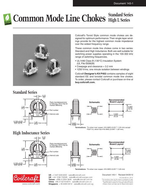
Document 143-1<strong>Common</strong> <strong>Mode</strong> <strong>Line</strong> <strong>Chokes</strong>Standard SeriesHigh L SeriesCoilcraft’s Toroid Style common mode chokes are designedfor optimum performance. Their single layer windingsprovide for the highest common mode impedanceover the widest frequency range.These common mode line chokes come in two series:Standard and High Inductance. Both are well suitable forswitching power supplies operating in the 100-300 kHzrange of switching frequencies.• UL1446 Class B (130°C) Insulation System(UL File E83628)• Creepage and clearance = 3.2 mm• 1250 Vrms, one minute isolation between windingsCoilcraft Designer’s Kit P402 contains samples of eightstandard EE and toroidal common mode line chokes.To order, please contact Coilcraft or purchase on-line atbuy.coilcraft.com.Standard Series1.2331,2maxP321x-ALCC-3YXXXX0.123,0Parts manufactured priorto February, 2012 maybemarked differently.Part numberInternal code12Schematic434 31RecommendedBoard Layout0.80020,3220.40010,160.150 ±0.033,81 ±0,76High Inductance Series0.150 ±0.033,81 ±0,761.4035,6max1 21.25max31,8P32xx-ALCC-3YXXXX0.123,01 21.40max35,6Parts manufactured priorto February, 2012 maybemarked differently.Part numberInternal code2 30.625max15,88Terminations: Tin-silver over copper; #16 AWG (0.051″ / 1,29 mm) exceptP3217-A, which has #18 AWG (0.040″ / 1,02 mm).2 30.900max22,8612Schematic43RecommendedBoard Layout4 310.90022,86Terminations: Tin-silver over copper; #16 AWG (0.051″ / 1,29 mm)20.60015,24US +1-847-639-6400 sales@coilcraft.comUK +44-1236-730595 sales@coilcraft-europe.comTaiwan +886-2-2264 3646 sales@coilcraft.com.twChina +86-21-6218 8074 sales@coilcraft.com.cnSingapore + 65-6484 8412 sales@coilcraft.com.sgDocument 143-1 Revised 04/20/12© Coilcraft Inc. 2012This product may not be used in medical of highrisk applications without prior Coilcraft approval.Specification subject to change without notice.Please check out web site for latest information.
Document 143-2Standard SeriesCurrent Leakage Interwinding LeadPart Inductance rating inductance SRF DCR max isolation diameter Weightnumber min (Amps) max (µH) typ (Ohms) (Volts rms) nom (g)P3213-AL 3.5 mH 1.3 62 500 kHz 0.150 1250 0.051/1,29 15.8P3214-AL 1.7 mH 2.0 32 850 kHz 0.065 1250 0.051/1,29 16.1P3215-AL 1.0 mH 3.2 22 1.25 MHz 0.036 1250 0.051/1,29 16.9P3216-AL 750 µH 5.0 19 1.30 MHz 0.022 1250 0.051/1,29 17.6P3217-AL 425 µH 8.1 10 1.75 MHz 0.012 1250 0.040/1,02 18.2P3218-AL 275 µH 13.0 8 2.00 MHz 0.008 1250 0.051/1,29 19.81. All parts have #16 AWG solder coated copper wire leads except P3217-A, which has #18 AWG leads.2. Operating temperature range –40°C to +85°C.3. Electrical specifications at 25°C.4. Parts in bold type are included in Coilcraft Designer’s Kit P402.Shown here are typical common mode frequencyplots of each part number. The plotsindicate the relative performance of each partover the frequency range of most interest fordesigners of equipment that must meet FCCand VDE noise regulations. It is important tonote that only a common mode signal willbe attenuated as shown. Differential modepower such as 50/60 Hz power line currentsor data signals will pass through unimpededby the common mode impedance. The insertionloss for differential signals is shown inthe lower graph. These data were taken in a50 Ohm system. All parts should be testedusing an appropriate <strong>Line</strong> Impedance StabilizationNetwork (LISN) when testing EMI/RFI performance of off-line power converters.<strong>Common</strong> <strong>Mode</strong> Attenuation*Attenuation (dB)05P3218-A10P3217-A15P3215-AP3216-A2025P3214-A30P3213-A354045500.0001 0.001 0.01 0.1 1 10 100Frequency (MHz)Differential <strong>Mode</strong> Attenuation*0P3215-A, P3216-A,P3217-A, P3218-AP3214-AAttenuation (dB)51015P3213-A200.0001 0.001 0.01 0.1 1 10 100Frequency (MHz)*measured on Agilent/HP 3577A network analyzer.US +1-847-639-6400 sales@coilcraft.comUK +44-1236-730595 sales@coilcraft-europe.comTaiwan +886-2-2264 3646 sales@coilcraft.com.twChina +86-21-6218 8074 sales@coilcraft.com.cnSingapore + 65-6484 8412 sales@coilcraft.com.sgDocument 143-2 Revised 04/20/12© Coilcraft Inc. 2012This product may not be used in medical of highrisk applications without prior Coilcraft approval.Specification subject to change without notice.Please check out web site for latest information.
Document 143-3High Inductance SeriesCurrent Leakage Interwinding LeadPart Inductance rating inductance SRF DCR max isolation diameter Weightnumber min (Amps) max (µH) typ (Ohms) (Volts rms) nom (g)P3219-AL 10.8 mH 1.3 165 125 kHz 0.29 1250 0.051/1,29 36.0P3220-AL 7.0 mH 2.0 100 225 kHz 0.15 1250 0.051/1,29 38.3P3221-AL 3.7 mH 3.2 60 400 kHz 0.08 1250 0.051/1,29 38.7P3222-AL 2.2 mH 5.0 35 600 kHz 0.04 1250 0.051/1,29 40.4P3223-AL 1.1 mH 8.1 20 900 kHz 0.02 1250 0.040/1,02 40.9P3224-AL 0.58 mH 13.0 10 1150 kHz 0.01 1250 0.051/1,29 40.91. All parts have #16 AWG solder coated copper wire leads except P3223-A, which has #18 AWG leads.2. Operating temperature range –40°C to +85°C.3. Electrical specifications at 25°C.Shown here are typical common mode frequencyplots of each part number. The plotsindicate the relative performance of each partover the frequency range of most interest fordesigners of equipment that must meet FCCand VDE noise regulations. It is important tonote that only a common mode signal willbe attenuated as shown. Differential modepower such as 50/60 Hz power line currentsor data signals will pass through unimpededby the common mode impedance. The insertionloss for differential signals is shown inthe lower graph. These data were taken in a50 Ohm system. All parts should be testedusing an appropriate <strong>Line</strong> Impedance StabilizationNetwork (LISN) when testing EMI/RFI performance of off-line power converters.<strong>Common</strong> <strong>Mode</strong> Attenuation*Attenuation (dB)0P3224-A10P3223-AP3222-A20P3221-A30P3220-A40P3219-A50600.0001 0.001 0.01 0.1 1 10 100Frequency (MHz)Differential <strong>Mode</strong> Attenuation*0P3223-A, P3224-AP3222-AP3221-AAttenuation (dB)1020P3220-AP3219-A300.0001 0.001 0.01 0.1 1 10 100Frequency (MHz)*measured on Agilent/HP 3577A network analyzer.US +1-847-639-6400 sales@coilcraft.comUK +44-1236-730595 sales@coilcraft-europe.comTaiwan +886-2-2264 3646 sales@coilcraft.com.twChina +86-21-6218 8074 sales@coilcraft.com.cnSingapore + 65-6484 8412 sales@coilcraft.com.sgDocument 143-3 Revised 04/20/12© Coilcraft Inc. 2012This product may not be used in medical of highrisk applications without prior Coilcraft approval.Specification subject to change without notice.Please check out web site for latest information.


