
Create successful ePaper yourself
Turn your PDF publications into a flip-book with our unique Google optimized e-Paper software.
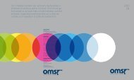
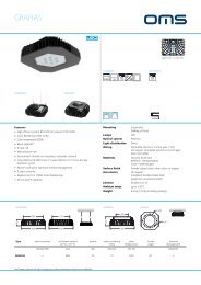
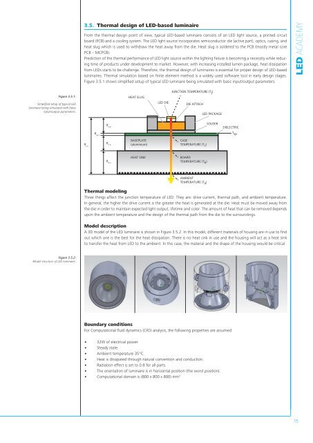
3.5. Thermal design of <strong>LED</strong>-based luminaireFrom the thermal design point of view, typical <strong>LED</strong>-based luminaire consists of an <strong>LED</strong> light source, a printed circuitboard (PCB) and a cooling system. The <strong>LED</strong> light source incorporates semiconductor die (active part), optics, casing, andheat slug which is used to withdraw the heat away from the die. Heat slug is soldered to the PCB (mostly metal corePCB – MCPCB).Prediction of the thermal performance of <strong>LED</strong> light source within the lighting fixture is becoming a necessity while reducingtime of products under development to market. However, with increasing installed lumen package, heat dissipationfrom <strong>LED</strong>s starts to be challenge. Therefore, the thermal design of luminaires is essential for proper design of <strong>LED</strong>-basedluminaires. Thermal simulation based on finite element method is a widely used software tool in early design stages.Figure 3.5.1 shows simplified setup of typical <strong>LED</strong> luminaire being simulated with basic input/output parameters.<strong>LED</strong> <strong>ACADEMY</strong>Figure 3.5.1:Simplified setup of typical <strong>LED</strong>luminaire being simulated with basicinput/output parameters.HEAT SLUGJUNCTION TEMPERATURE (T j )<strong>LED</strong> DIEDIE ATTACH<strong>LED</strong> PACKAGER j-aR c-bR sp-cR j-spBASEPLATE(aluminium)CASETEMPERATURE (T c )SOLDERDIELECTRICT spR b-aHEAT SINKBOARDTEMPERATURE (T b )AMBIENTTEMPERATURE (T a )Thermal modelingThree things affect the junction temperature of <strong>LED</strong>. They are: drive current, thermal path, and ambient temperature.In general, the higher the drive current is the greater the heat is generated at the die. Heat must be moved away fromthe die in order to maintain expected light output, lifetime and color. The amount of heat that can be removed dependsupon the ambient temperature and the design of the thermal path from the die to the surroundings.Model descriptionA 3D model of the <strong>LED</strong> luminaire is shown in Figure 3.5.2. In this model, different materials of housing are in use to findout which one is the best for the heat dissipation. There is no heat sink in use and the housing will act as a heat sinkto transfer the heat from <strong>LED</strong> to the ambient. In this case, the material and the shape of the housing would be critical.Figure 3.5.2:Model structure of <strong>LED</strong> luminaire.Boundary conditionsFor Computational fluid dynamics (CFD) analysis, the following properties are assumed:• 32W of electrical power• Steady state.• Ambient temperature 35°C.• Heat is dissipated through natural convention and conduction.• Radiation effect is set to 0.8 for all parts.• The orientation of luminaire is in horizontal position (the worst position).• Computational domain is (800 x 800 x 800) mm 315