
You also want an ePaper? Increase the reach of your titles
YUMPU automatically turns print PDFs into web optimized ePapers that Google loves.
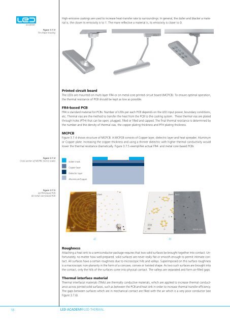
High-emissive coatings are used to increase heat-transfer rate to surroundings. In general, the duller and blacker a materialis, the closer its emissivity is to 1. The more reflective a material is, its emissivity is closer to 0.Figure 3.7.3:Fin-shape housing.Printed circuit boardThe <strong>LED</strong>s are mounted on multi-layer FR4 or on metal core printed circuit board (MCPCB). To ensure optimal operation,the thermal resistance of PCB should be kept as low as possible.FR4-based PCBFR4 is standard material for PCBs. Number of <strong>LED</strong>s per each PCB depends on the <strong>LED</strong> input power, boundary conditions,etc. Thermal vias are the method to transfer the heat from the PCB to the cooling system. These thermal vias are platedthrough holes (PTH) that can be open, plugged, filled or filled and capped. The final thermal resistance is determined <strong>by</strong>the number and the density of thermal vias, the copper plating thickness and PTH plating thickness.MCPCBFigure 3.7.4 shows structure of MCPCB. A MCPCB consists of Copper layer, dielectric layer and heat spreader, Aluminumor Copper plate. Increasing the copper thickness and using a thinner dielectric with higher thermal conductivity wouldlower the thermal resistance dramatically. Figure 3.7.5 exemplifies actual FR4- and metal core-based PCBsFigure 3.7.4:Cross section of MCPBC (not to scale).Solder maskCopper layerDielectric layerAlluminium/CopperFigure 3.7.5:(a) FR4-based PCB,(b) metal core-based PCB.back / frontfront / backFR4metal corea) b)RoughnessAttaching a heat sink to a semiconductor package requires that two solid surfaces be brought together into contact. Unfortunately,no matter how well-prepared, solid surfaces are never really flat or smooth enough to permit intimate contact.All surfaces have a certain roughness due to microscopic hills and valleys. Superimposed on this surface roughnessis a macroscopic non-planarity in the form of a concave, convex or twisted shape. As two such surfaces are brought intothe contact, only the hills of the surfaces come into physical contact. The valleys are separated and form air-filled gaps.Thermal interface materialThermal interfacial materials (TIMs) are thermally conductive materials, which are applied to increase thermal conductanceacross jointed solid surfaces, such as between the PCB and heat sink in order to increase thermal transfer efficiency.The gaps between surfaces which are in mechanical contact are filled with the air which is a very poor conductor (seeFigure 3.7.6).18<strong>LED</strong> <strong>ACADEMY</strong>/<strong>LED</strong> THERMAL