WINE-MATE Cooling Unit Use & Care Manual - Air & Water
WINE-MATE Cooling Unit Use & Care Manual - Air & Water
WINE-MATE Cooling Unit Use & Care Manual - Air & Water

Create successful ePaper yourself
Turn your PDF publications into a flip-book with our unique Google optimized e-Paper software.
<strong>WINE</strong>-<strong>MATE</strong> <strong>Cooling</strong> <strong>Unit</strong><strong>Use</strong> & <strong>Care</strong> <strong>Manual</strong>VINO1500CD, CTEDVINO2500CD, CTEDVinotemp International Corp.www.winemate.com
Important Safety Information• DO NOT PLUG IN UNTIL 24 HOURS AFTER DELIVERY.• DO NOT USE A GROUND FAULT INTERRUPTER (GFI).• A DEDICATED 15 AMPCIRCUIT IS HIGHLY RECOMMENDED.- 1 -
TABLE OF CONTENTSFeature Description…………………………….……………..3Installation Instruction………………………………………..5Temperature Control & Humidity Adjustment………….9<strong>Care</strong> Guide……………………………………………………13Troubleshooting……………………………………………..14Wiring Diagram……………………………………….………17Customer Support……………………………………………18Warranty……………………………………………………….19- 2 -
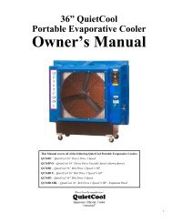
Feature Description• VINO1500CD, CTED and VINO2500CD, CTED cooling units are designedand used to provide a subtle temperature between 50~65 °F for suitablespace at a normal environment.• The refrigerated space will maintain humidity of 50~70% RH even whenthe environment becomes dry and humid.• These temperatures and humilities are optimized for long term storage ofwine.• Bottom cold-air supply is optimized for use in the wine cabinets.• Multiple options for top and rear hot air exhaust• Self-contained ready for use and easy for installationFig. 1.1 FEATURES- 3 -
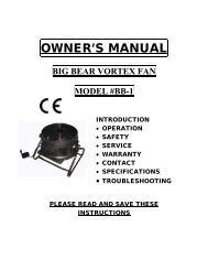
Fig. 1.2 DIMENSIONS (in)The dimension and capacity are specified as follows:Model1500cd1500cted2500cd2500ctedExhaustRear ExhaustTop ExhaustRear ExhaustTop Exhaust<strong>Cooling</strong>Capacity, CFM55°F/ 75°F1500 Btu/h,120 CFM1500 Btu/h,120 CFM2500 Btu/h,180 CFM2500 Btu/h,180 CFMBottleCapacity55°F/ 75°F150 800cu ft bottles150 800cu ft bottles250 1200cu ft bottles250cu ft1200bottlesElectrical Weight115V/60Hz4A115V/60Hz4A115V/60Hz5A115V/60Hz5A50 lb50 lb55 lb55 lb• See the voltage, frequency and current specified on the label at thecooling unit.- 4 -
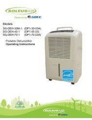
Installation Instruction1. Cabinet Location• Place the wine cabinet in a properly ventilated location. Otherwise, heatexhausted by the cooling unit will build up and it will not operate properly.• The exhaust area must not be a closed space and must be ventilated. Theambient temperatures shall not be higher than 90 °F or lower than 50 °F.1) Rear Exhaust Location• Leave min 6 “clearance from the rear to the wall.• Leave min 12” clearance from the top to the ceiling.• Leave min 6” clearance from the left and right sides.2) Front Exhaust Location• Leave min 6” clearance from the front if left and right sides unobstructed.• Or, leave min 36” clearance from the front if left and right sides obstructed3) Top Exhaust Location• Leave min 12” from the top to the ceiling.• Leave min 2 “clearance from the rear to the wall.• Leave min 2” clearance from the left and right sides.4) Side Exhaust Location• Leave min 6 “clearance from the left or right side to the wall.• Leave min 12” clearance from the top to the ceiling.2. <strong>Cooling</strong> <strong>Unit</strong> Installation• The cooling unit produces cooling supplied into the cabinet, and it alsogenerates heat that must be exhausted outside the cabinet. So the supplyside and exhaust side must be separated and sealed (see Fig. 2.1).• Cut a rectangular inside opening at the rear of the cabinet with the 1/4”clearance inwards to the width and height of the cooling unit. By not goingthrough, leave 1/2” lip inside at the wall to place the gaskets (see Fig. 2.2).• If top exhaust, cut another rectangular opening at the top of the cabinet tothe length and width of the top exhaust (see Fig.2.2).• Make 2 holes at the ceiling to install the 1/4 inside diameter wood threadinserts (see Fig.2.2).• Place the gaskets (1/2” foam tape)on the gasket lips (see Fig 2.1).• If top exhaust, place another gaskets along the top exhaust at the top ofthe cooling unit (see Fig.2.3).• Move the cooling unit towards the mounting sides and push to press thegaskets.• Fasten the 2 brackets and use 7/16” wrench to tighten the two ¼” screws(see Fig 2.1).- 5 -
• Attach the exhaust and fresh air grille with screws from the rear side of thecabinet.• If top exhaust, install another top exhaust grille at the top of the cabinet.• Plug the cooling unit in receptacle.• Plug the wine cabinet.Fig. 2.1 COOLING UNIT MOUNTING- 6 -
Fig. 2.2 MOUNTING CUTOUT & GASKET LIPSFig. 2.3 TOP EXHAUST GASKETNOTES:1) DO NOT INSTALL ANY DUCTS ONTO THE SUPPLY, INTAKE ANYEXHAUST.2) MOUNTING BRACKETS, SCREWS, GASKETS AND OTHER SEAL<strong>MATE</strong>RIALS ARE NOT INCLUDED.- 7 -
2. Electrical Cord• We strongly recommend against the use of an extension cord. However, ifyou still select to use an extension cord, it is absolutely necessary that it isa UL LISTED 3-wire grounding type appliance extension cord. Themarked rating of the extension cord shall be 115 V, 15 A. or equivalentand not greater than 15ft in length.- 8 -
Temperature Control & Humidity Adjustment1. Temperature Setting• Set the temperature at 55 °F for the optimum aging of wine• On initial start-up, the time required to reach the desired temperaturewill vary, depending on the quantity of bottles, temperature settingand surrounding temperature.• Allow 24 hours to stabilize the temperature for each new temperaturesetting operation2. <strong>Use</strong> of the controllerFig. 3.1 DIGITAL CONTROLLER1) DisplayDuring normal operating conditions, the display shows the value measured bythe air regulation probe. In case of active alarm, the temperature flashesalternately to the code alarm.1.1 LED Functions1.2 Front Panel Commands- 9 -
2) Alarm Signals2.1 Code Description2.2 Alarm RecoveryProbe alarms P1”, start a few seconds after the fault in the related probe; theyautomatically stop a few seconds after the probe restarts normal operation.Check connections before replacing the probe. Temperature alarms “HA”, “LA”automatically stops as soon as the temperature returns to normal value. Alarm“CA” (with i1F=PAL) recovers only by switching off and on the instrument.3) Temperature Set-Point3.1 How to see the set-point1. Push and immediately release the SET key: the display will show the Setpoint;2. Push and immediately release the SET key or wait for 5 seconds to display theprobe value again.3.2 How to change the set-point1. Push the SET key for more than 3 seconds to change the Set point value;- 10 -
2. The value of the set point will be displayed and the “°C” or “°F” LED startsblinking;3. To change the Set value, push the keys or arrows within 10s.4. To memorize the new set point value, push the SET key again or wait 10s.4) Humidity AdjustmentThe parameter Fon is used to adjust the humidity in the wine cabinet. The highervalue of Fon, the higher relative humidity will be.1. Press the Set + keys for 3 sec until the “°C” or “°F” LED starts blinking.2. Release the keys, then push again the Set + keys for more than 7sec, thePr2 label will be displayed.3. Release the keys, select the required parameter Fon by up or down keys .4. Press the “SET” key to display its value.5. <strong>Use</strong> up or down keys to change its value.6. The default value is 0, change high or low value to maintain high or lowhumidity.7. Press “SET” to store the new value.8. To exit: Press SET + or wait 15sec without pressing a key.5) Regulation DifferentialThe parameter Hy is used as intervention differential for set point. Compressorcut-in is the set-point + Hy, and compressor cut-out is the set-point.1. Press the Set + keys for 3 sec until the “°C” or “°F” LED starts blinking.2. Release the keys, then push again the Set + keys for more than 7sec, thePr2 label will be displayed.3. Release the keys, HY will display immediately.4. Press the “SET” key to display its value.5. <strong>Use</strong> up or down keys to change its value.6. The default value is 4, change high or low value to result in long high or shortrunning cycle.7. Press “SET” to store the new value.8. To exit: Press SET + or wait 15sec without pressing a key.6) Defrost CycleThe parameter IdF is used as interval between defrost cycles.1. Press the Set + keys for 3 sec until the “°C” or “°F” LED starts blinking.2. Release the keys, then push again the Set + keys for more than 7sec, thePr2 label will be displayed.3. Release the keys, select the required parameter IdF by up or down keys .4. Press the “SET” key to display its value.5. <strong>Use</strong> up or down keys to change its value.6. The default value is 24, change high or low value to result in less or moredefrost cycle.7. Press “SET” to store the new value.8. To exit: Press SET + or wait 15sec without pressing a key.- 11 -
7) <strong>Manual</strong> DefrostPush the DEF key for more than 2 seconds and a manual defrost will start.- 12 -
<strong>Care</strong> GuideI. Condenser Coil CleaningI• The condenser coil is on the ambient air intake side of the cooling unit.• Clean the condenser coil regularly. Coil may need to be cleaned at leastevery 6 months.• Unplug the cooling unit or disconnect power.• <strong>Use</strong> a vacuum cleaner with an extended attachment to clean the coil when itis dusty or dirty.• Plug the cooling unit or reconnect power.II. Moisture Removing• Remove the extra condensate if it is accumulated in the wine cabinet athumidity condition.- 13 -
TroubleshootingThis Troubleshooting Chart is not prepared to replace the training required for aprofessional refrigeration service person, not is it comprehensiveTroubleshooting ChartComplaint Possible Causes Responsea. Power cord unpluggedb. No power to unitc. Setting higher than ambienttemperatured. Differential too highe. Incorrect or loose wiringsf. Low voltageg. Defrost light blinkingh. Compressor light blinking1.<strong>Unit</strong> notrunning2.Fan runningcontinually3.Temperaturefluctuatinga. Post-compressor fan runningmode for humidity modulationa. Check for power cord plugb. Check power at receptacle & fusesc. Lower temperature settingd. Decrease the value as to 4 °Fe. Check all wirings and connectionsf. Contact an authorized electriciang. <strong>Unit</strong> is under defrost modeh. <strong>Unit</strong> waits for anti-short cycle delaya. See 4) to set FON = 0a. <strong>Air</strong> sensor a. When using an air sensor, the winebottle temperature is mainlycontrolled by the average airtemperature. If the set-point is 55°Fwith the differential 4F, the coolingunit turns on at 59°F of airtemperature and turns off at 55°F ofair temperature. The average airtemperature is 57°F, and then thewine temperature is around 57+/-0.5°F. The air is light enough tochange so quickly that it maintainsrelatively constant averagetemperature that would prevent winebottle temperature from varying.4.Temperaturehigh, unitstopping andstarting butshortrunning time5. Temperaturehigh,compressorstopping andstarting butshortrunning timea. Displaying 55°F, air sensorcontacting the evaporator or inthe supply airb. Setting too higha. Incorrect voltageb. Failed thermistorc. Failed componentsd. Improper condenser airflowe. Dirty condenserf. Overcharge of refrigerantg. Discharge or suction pressuretoo higha. Move the air sensor away from theevaporator and supply airb. Lower settinga. Check for voltageb. Check thermistor by placing it in icewater and measuring resistancec. Check compressor windings, startrelay and overload protector.d. Check for condenser fane. Clean condenserf. Call service for removing refrigerantg. Call service for OEM information- 14 -
6. “HA” alarmblinking andbeeping,temperaturehigh or notcooling andrunningcontinually7.<strong>Unit</strong> runningtoo long8.Fan motorrunning butcompressornot running9.Compressorrunning butfan notrunning10.EvaporatorIcinga. Improper room insulation & sealb. Room too largec. Ambient temperature too highd. Exhaust restrictede. Malfunctioning fansf. Improper evaporator orcondenser airflowg. Dirty Condenserh. Iced evaporatori. Refrigeration system restrictionj. Refrigerant leakk. Undercharge or overchargel. Failed componentsa. Improper room insulation & sealb. Exhaust restrictedc. Room too larged. Ambient temperature higher >90°Fe. Dirty Condensera. Post-compressor fan runningmodeb. Incorrect power supplyc. Incorrect or loose wiringsd. Failed componentse. Liquid refrigerant in thecompressora. Fan blade stuckb. Incorrect or loose wiringsc. Failed motorsa. Evaporator air flow restrictionb. Not stopping due to air leak, highambient temperature or lowsettingc. Low ambient temperatured. Bad thermostat or sensore. Moisture in the systema. Check for insulation, gasket anddoor openingb. Check for excessive sizec. Check for installation locationd. Leave minimum 3 feet clearance forthe exhaust side and leaveminimum 1 foot clearance for thefresh air intake sidee. Check for both evaporator andcondenser fansf. Check for air restrictionsg. Clean condenserh. Defrost and reset temperaturei. Call service for checkingrestrictionsj. Call service for checking loss ofrefrigerantk. Call service to add or removerefrigerantl. Check compressor windings, startrelay and overload protectora. Check for insulation, gasket anddoor openingb. Leave minimum 3 feet clearance forthe exhaust side and leave minimum1 foot clearance for the fresh airintake sidec. Check for excessive size or increasesettingd. Check for installation location orincrease settinge. Clean condensera. Check for fan running time FONb. Check for proper voltagec. Check all wirings and connectionsd. Check start relay, start capacitor,overload protector, compressor.e. Call service for OEM information.a. Check for proper clearanceb. Check all wiringsc. Call service for checking open orshorted windingsa. Check for fansb. Check for seal, door opening,ambient temperature and settingc. Defrost unitd. Check for thermostat and sensore. Working initially then stopping- 15 -
11.<strong>Water</strong> leak12.Circuittripping13.Noisyoperationf. Refrigerant low or leakingg. Capillary tube blockagea. High humidityb. <strong>Air</strong> leak in wine cellarc. Evaporator air flow restrictiond. <strong>Water</strong> passages restrictede. Drip tray leaka. Incorrect fuse or breakerb. Incorrect wiringsc. Failed componentsa. Mounting area not firmb. Loose partsc. Compressor overloaded due tohigh ambient temperatures orairflow restrictiond. Malfunctioning componentsf. Check for current and sealedsystem leakageg. Check for low side pressurea. <strong>Use</strong> drain lineb. Check for any air leakc. Check air flow or air TD crossingevaporatord. Clean the drip traye. No water overflow but leaka. Check for proper fuse or breakerb. Check for wirings and connectionsc. Call servicea. Add support to improve installationb. Check fan blades, bearings, cabinetwashers, tubing contact and loosescrews.c. Check for airflow blockaged. Call service for checking internalloose, inadequate lubrication andincorrect wirings- 16 -
Wiring DiagramFig. 6.1 WIRING DIAGRAMFig. 6.2 CALLING FEATURE WIRING DIAGRAM- 17 -
Customer SupportIf you still have problems, please contact us at:Vinotemp International17631 South Susana RoadRancho Dominguez, CA 90221Tel: (310) 886-3332Fax: (310) 886-3310Email: info@vinotemp.com- 18 -
WarrantyThank you for choosing a Vinotemp cooling unit.Please enter the complete model and serial numbers in the space provided:Model_________________________________________________________Serial No.______________________________________________________Attach your purchase receipt to this owner’s manual.1. Limited WarrantyVINOTEMP warrants its products to be free from defects due to workmanship ormaterials under normal use and service, for twelve months after the initial sale. Ifthe product is defective due to workmanship or materials, is removed withintwelve months of the initial sale and is returned to VINOTEMP, in the originalshipping carton, shipping prepaid, VINOTEMP will at its option, repair or replacethe product free of charge. Additionally VINOTEMP warrants all parts to be freefrom defects for a period of sixty months after initial sale.This warranty constitutes the entire warranty of the VINOTEMP with respect to itsproducts and is in lieu of all other warranties, express or implied, including any offitness for a particular purpose. In no event shall VINOTEMP be responsible forany consequential damages what is so ever. Any modification or unauthorizedrepair of VINOTEMP products shall void this warranty.Service under WarrantyThis service is provided to customers within the continental UNITED STATESonly. VINOTEMP cooling units are warranted to produce the stated number ofBTU/H. While every effort has been made to provide accurate guidelines,VINOTEMP can not warranty its units to cool a particular enclosure.In case of failure, VINOTEMP cooling units must be repaired by the factory or itsauthorized agent. Repairs or modifications made by anyone else will void thewarranty.Shall a VINOTEMP cooling unit fail, contact the dealer for instructions, do notreturn the unit to the factory without authorization from VINOTEMP. If the unitrequires repair, re-pack it in the original shipping carton and return it to thefactory, shipping prepaid. VINOTEMP will not accept COD shipments. If the unit- 19 -
is determined to be faulty and is within the twelve month warranty periodVINOTEMP will, at its discretion, repair or replace the unit and return it free ofcharge to the original retail customer. If the unit is found to be in good workingorder, or beyond the initial twelve month period, it will be returned freight collect.2. Limitation of Implied WarrantyVINOTEMP’S SOLE LIABILITY FOR ANY DEFECTIVE PRODUCT IS LIMITEDTO, AT OUR OPTION, REPAIRING OR REPLACING OF UNIT.VINOTEMP SHALL NOT BE LIABLE FOR:DAMAGE TO OTHER PROPERTY CAUSED BY ANY DEFECTS IN THE UNIT,DAMAGES BASED UPON INCONVENIENCE, LOSS OF USE OF THE UNIT,LOSS OF TIME OR COMMERCIAL LOSS, ANY OUTER DAMAGES,WHETHER INCIDENTAL, CONSEQUENTIAL OR OTHERWISE.THIS WARRANTY IS EXCLUSIBE AND IS IN LIEU OF ALL OTHERWARRANTIES, EXPRESSED OR INPLIED, INCLUDING BUT NOT LIMITEDTO, IMPLIED WARRANTIES OF MERCHANTABILITY OR FITNESS FOR APARTICULAR PURPOSE.While great effort has been made to provide accurate guidelines VINOTEMPcannot warrant its units to properly cool a particular enclosure. Customers arecautioned that enclosure construction, unit location and many other factors canaffect the operation and performance of the unit. There for suitability of the unitfor a specific enclosure or application must be determined by the customer andcannot be warranted by VINOTEMP.- 20 -